On 22 March 2017 I went to the High Tech Campus in Eindhoven to attend a seminar about 'smarthomes' (presented by tweakers.net). I am renovating my bungalow from 1967 and was curious about the current state of technology for smarthomes. I decided to turn my home into a smarthome. It's already disconnected from the gas supply line and it will be a house with a heat pump and solar panels. So besides the water the house will be a 100% sustainable home.
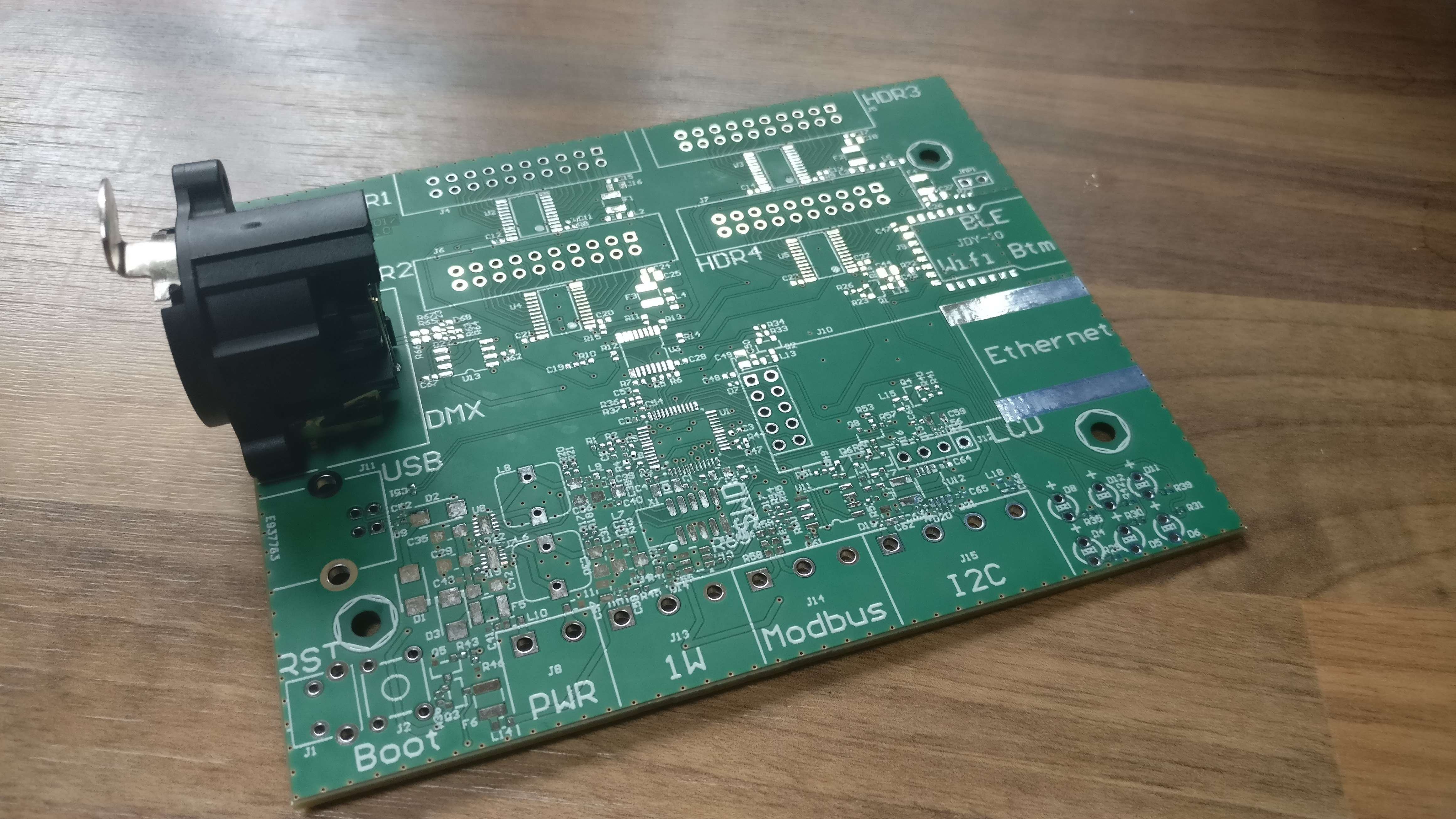
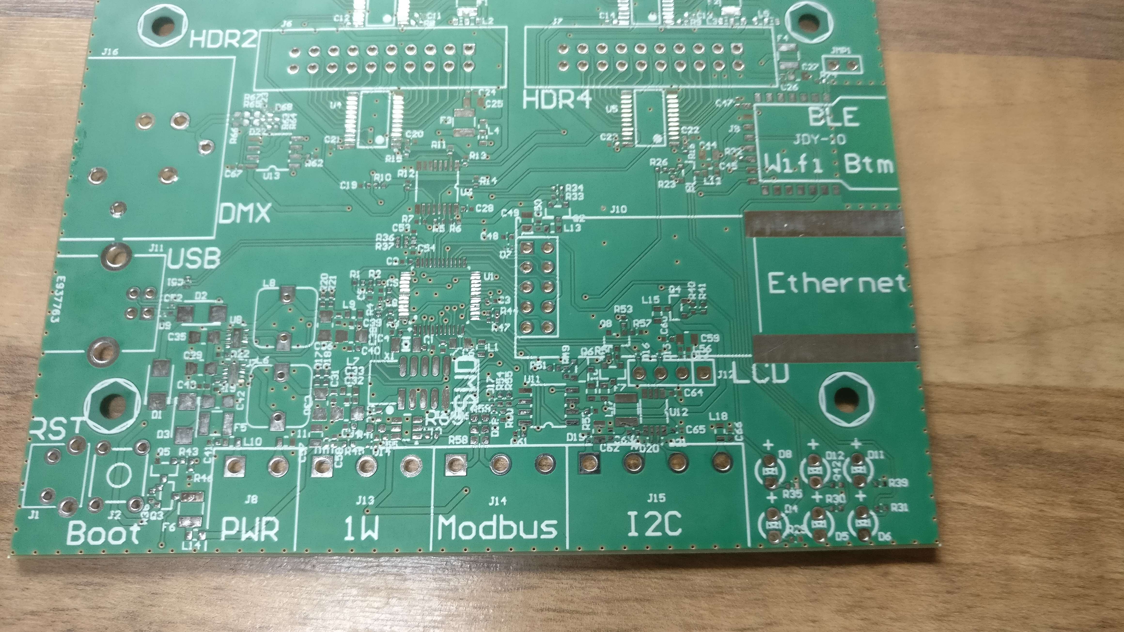
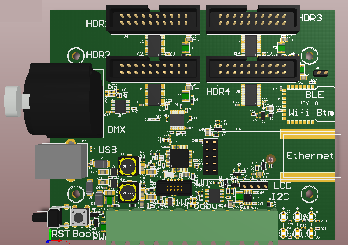
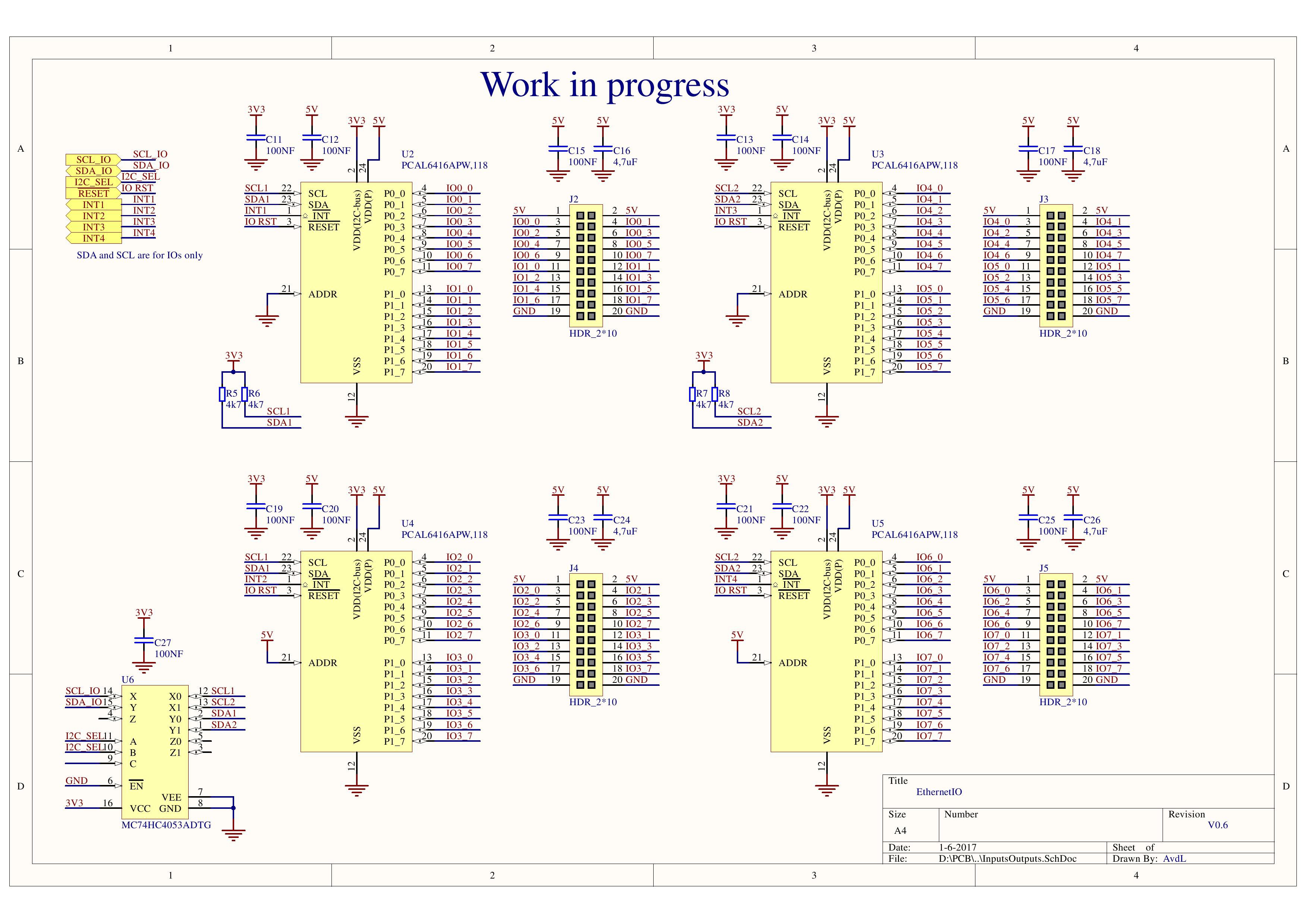
Now I am looking for a smart solution for my smarthome. The Loxone Miniserver is a very nice device, but additional KNX devices that you need for the system are very expensive. Let's make a cheaper and more flexible solution to expand the inputs & outputs. A device that can be connected to the network and send the active button signal to the Loxone by ethernet. There will be the following interfaces available: I2C, 1-wire, DMX, Modbus, Wifi/BLE, Ethernet. So this PCB can also be a network gateway to those interfaces. This project can also be used by someone that doesn't use a Loxone. With a webpage on the ATSAMD21 you can have a realtime insight in the digital inputs and set the digital outputs. But the device can also generate TCP request when an input changes. You can also connect some PIR sensors on the digital inputs (with a AC to DC level adapter in between) and generate an alarm when you're from home (send a notification by the internet to your phone).
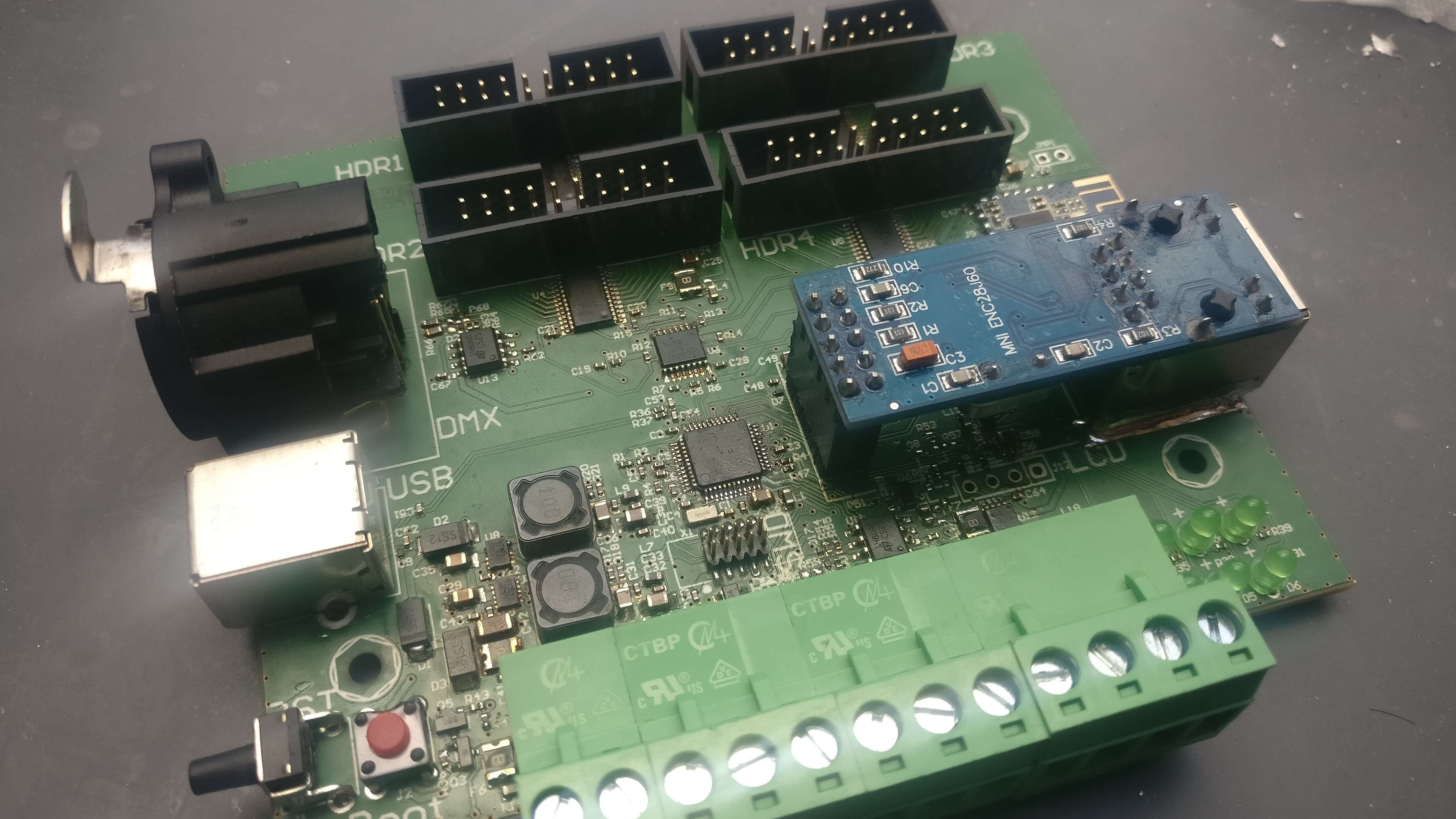
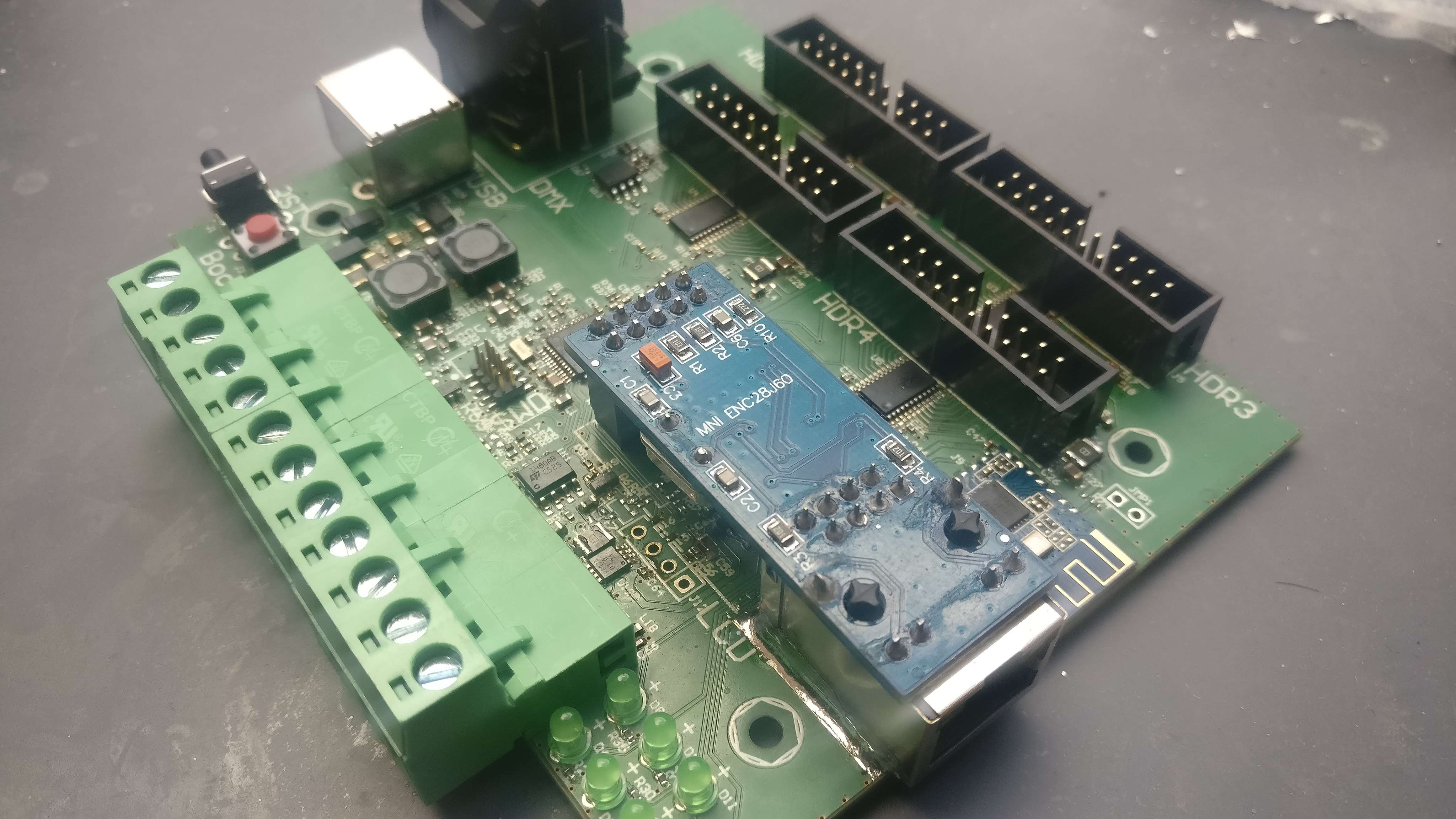
These are the specs of the final hardware:
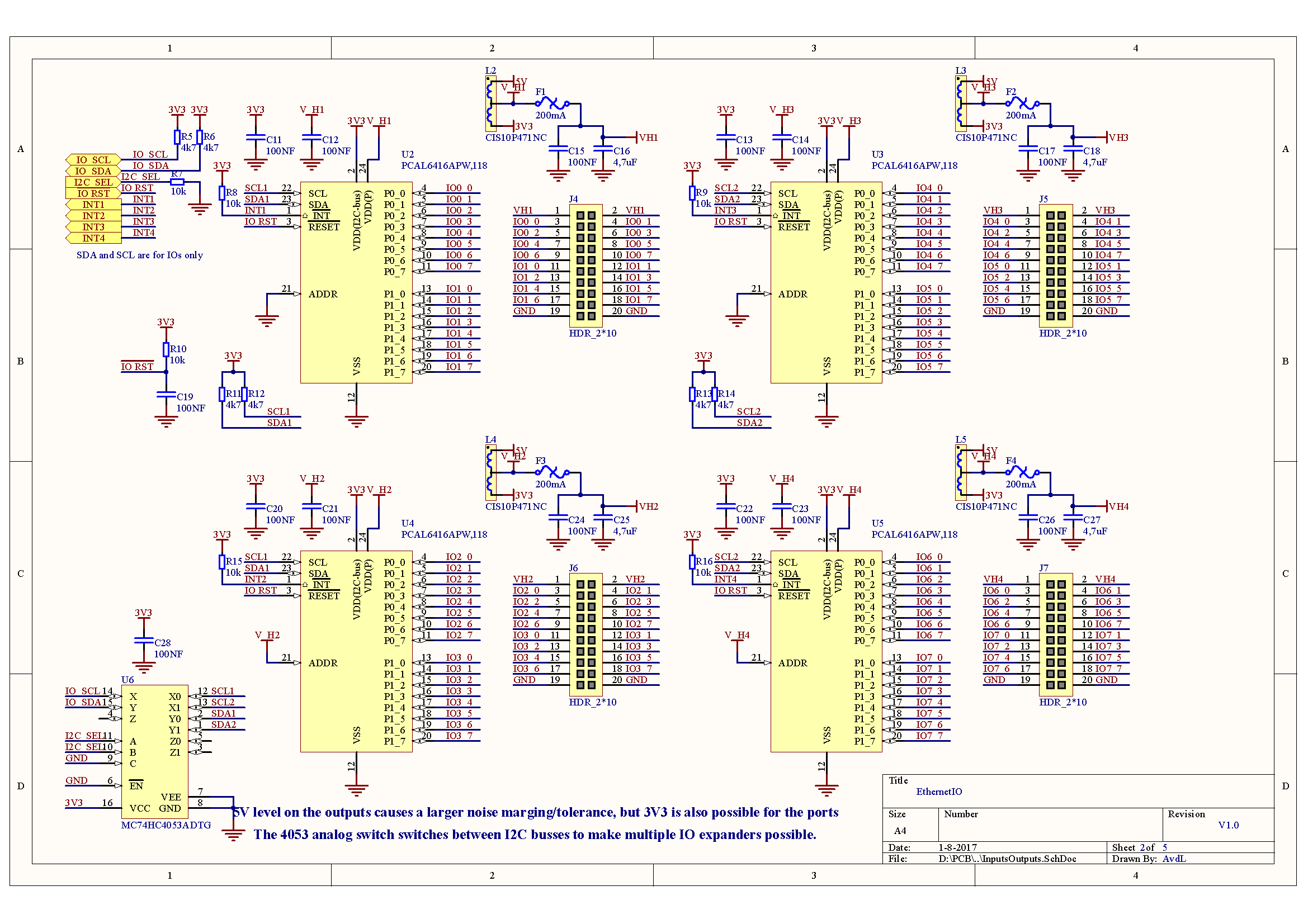
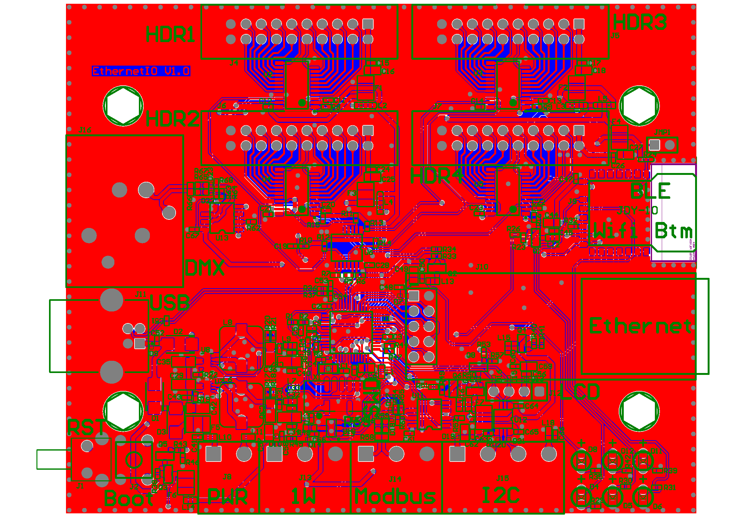
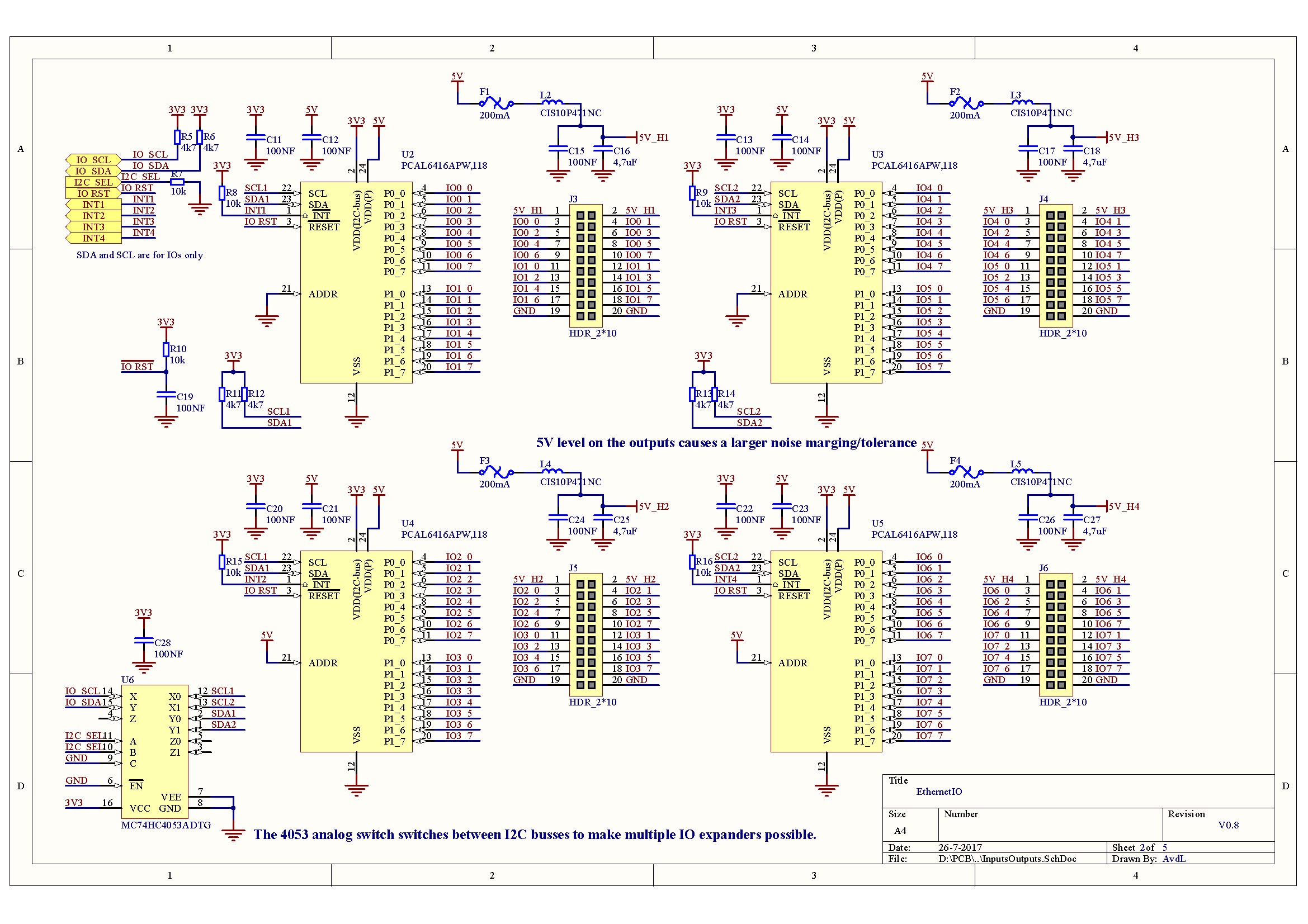
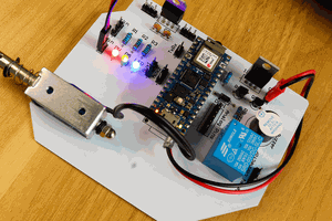
* 64 digital Inputs/Outputs. can be configured separately as inputs and outputs. Changing inputs will be processed immediately because this will raise an interrupt. Outputs can be connected to mechanical relay or SSR (https://www.aliexpress.com/item/10DA-Din-rail-SSR-quintuplicate-five-5-input-3-32VDC-output-24-380VAC-single-phase-DC/1581576845.html)
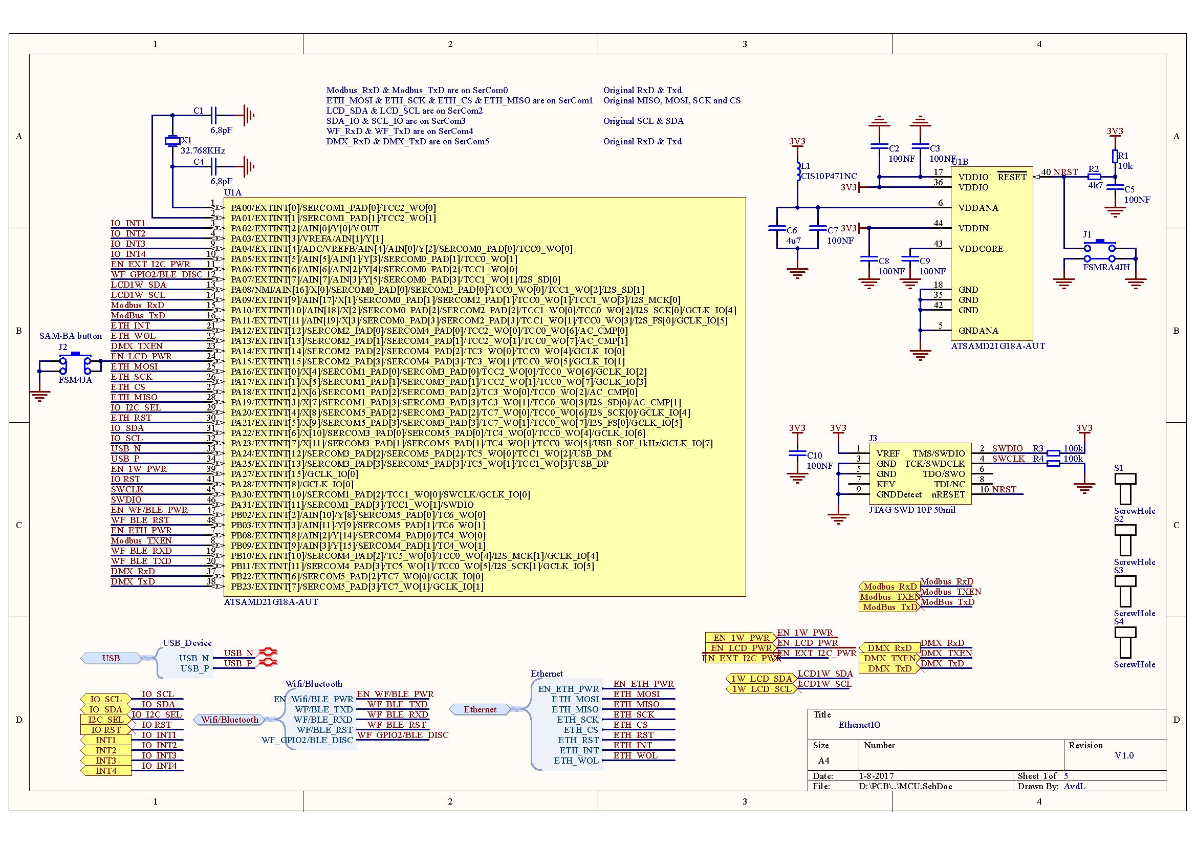
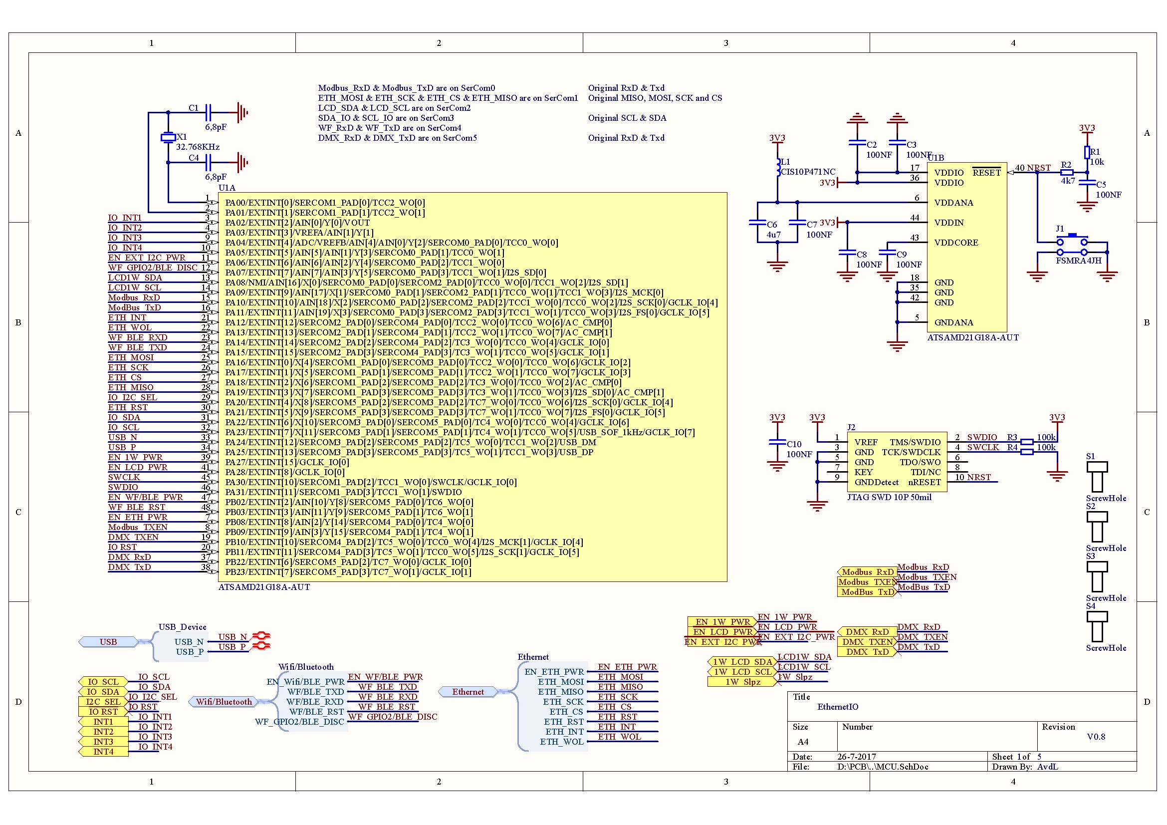
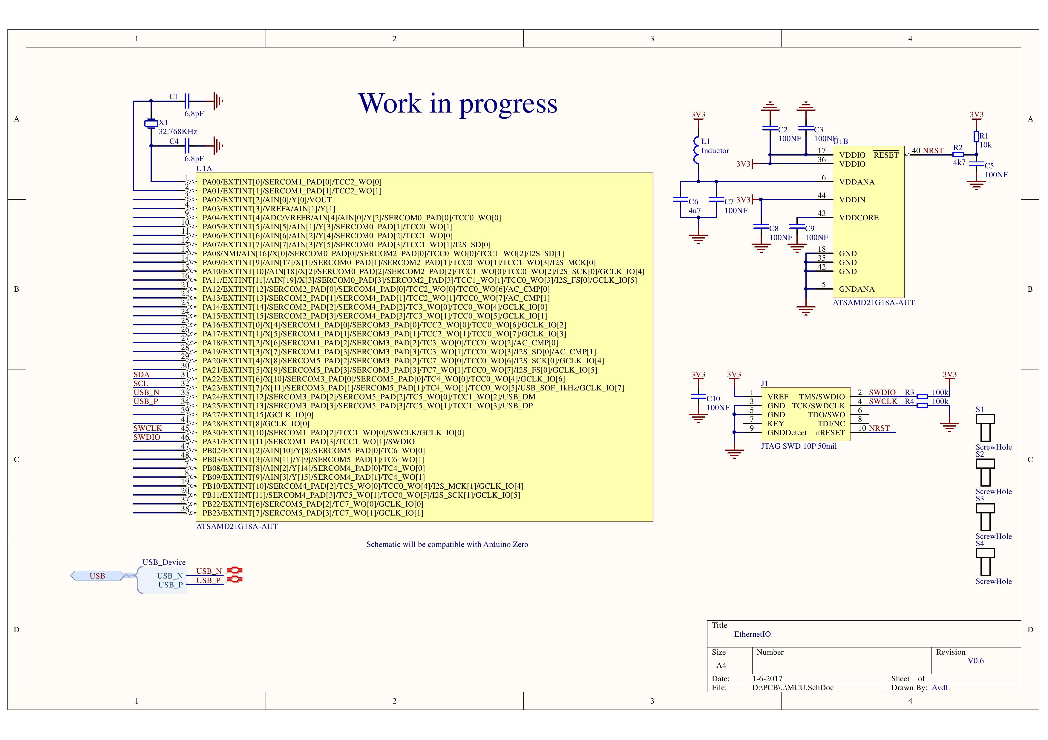
* controller is the ATSAMD21. This controller is Arduino M0 compatible (with the right firmware inside)
* The PCB can also be used as a standalone product (with webpage, etc.), but also as an IO extension for an existing home automation system.
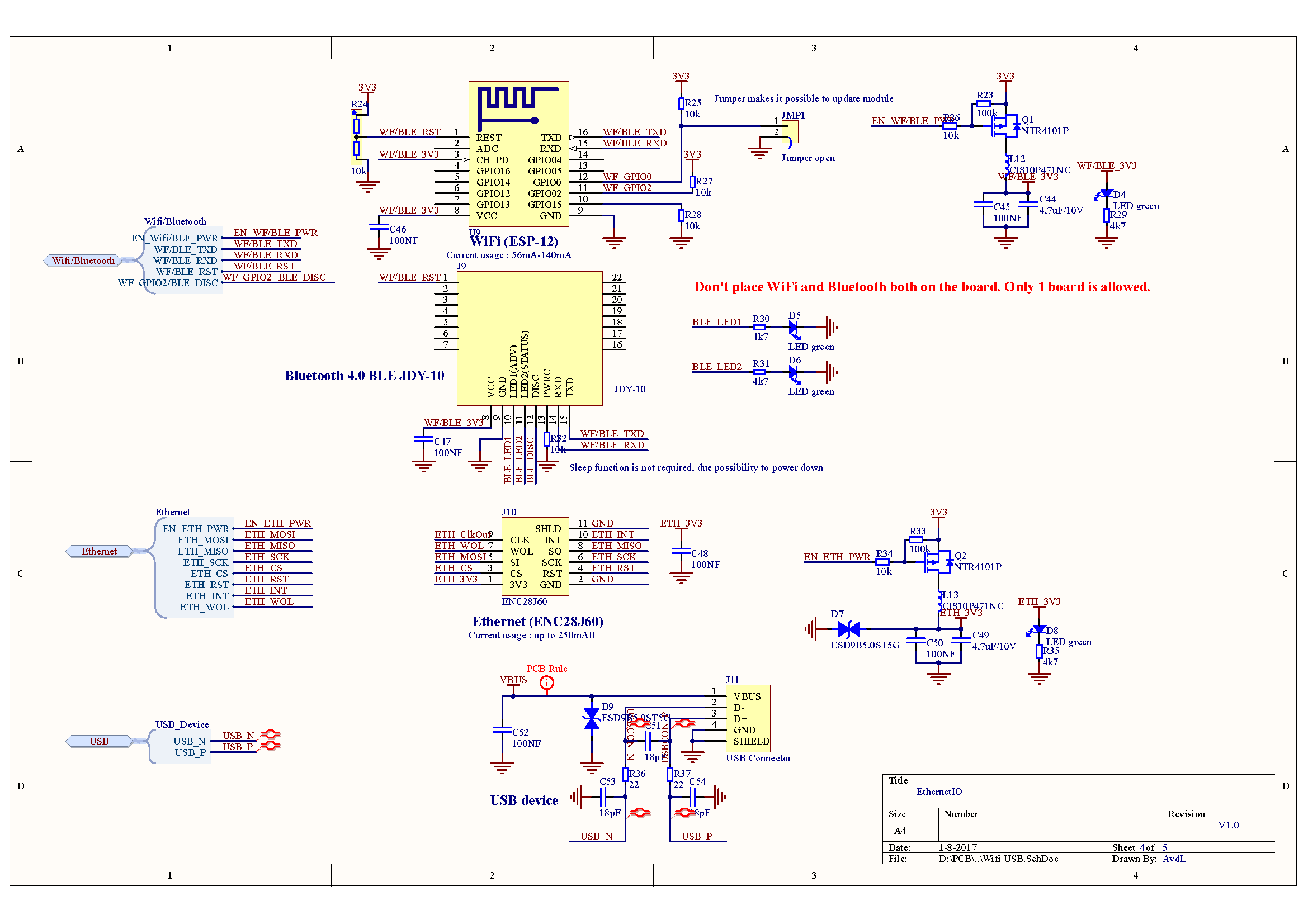
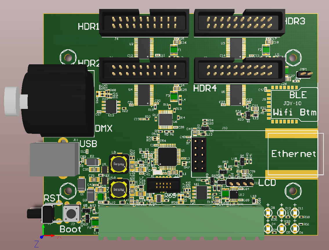
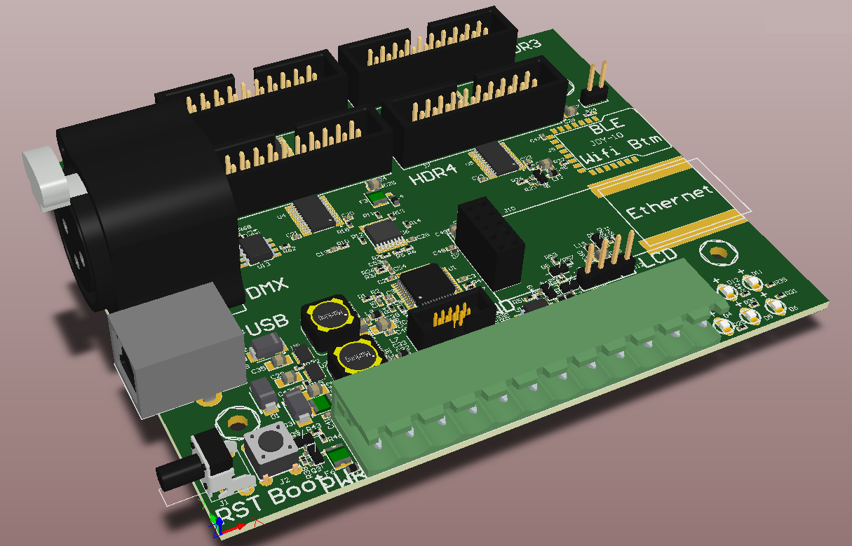
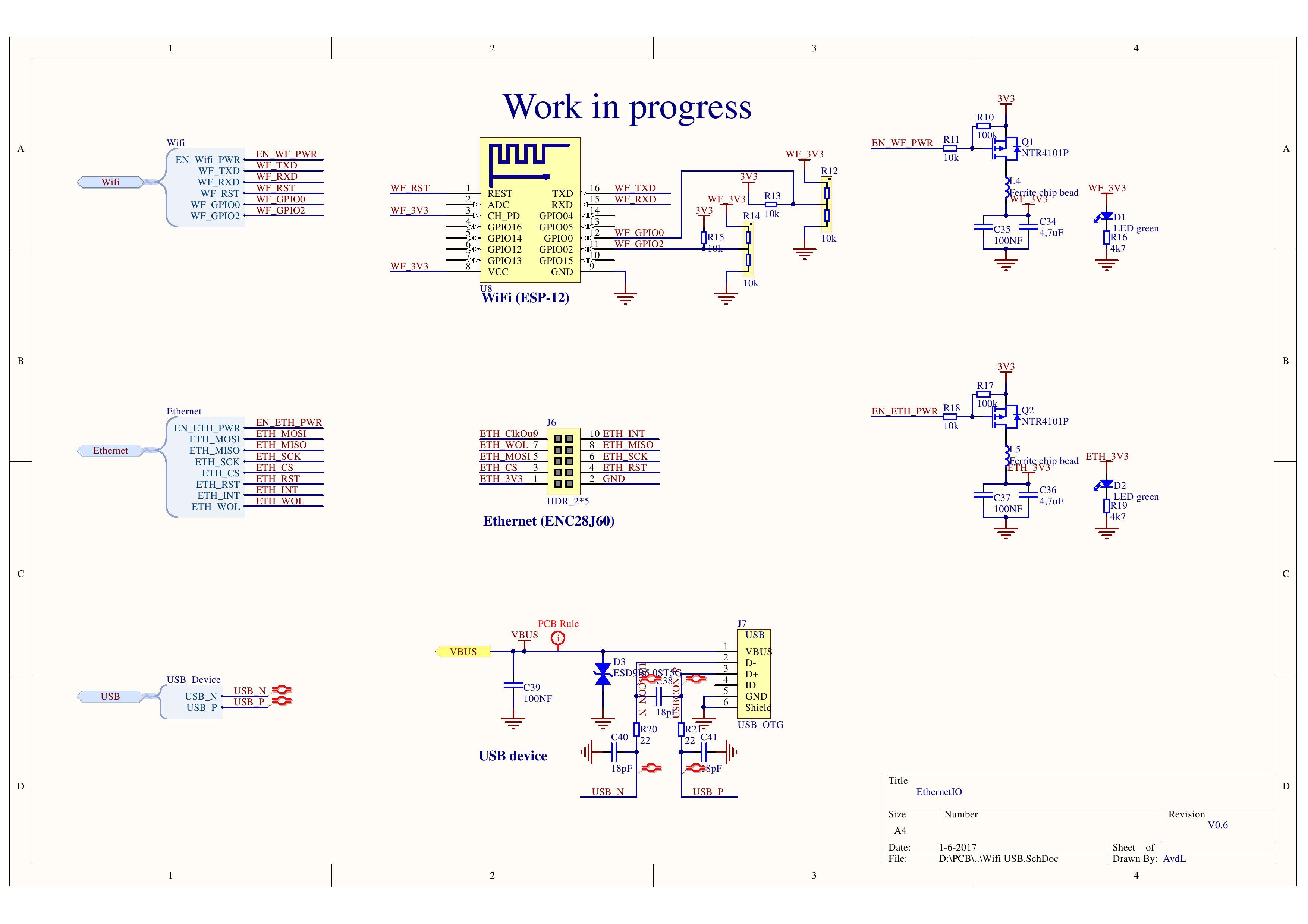
* USB device. The ATSAMD21 will on be a USB device. The 'old' standard USB connections are robust. This USB port will be used to update the controller.
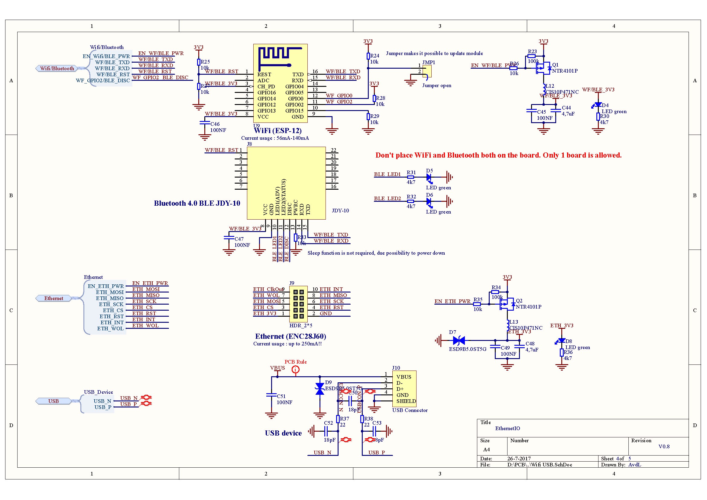
* Ethernet connection. The PCB has a place for the ENC28j60 device (SPI to ethernet).
* Wifi or BLE module will provide additional communication options.
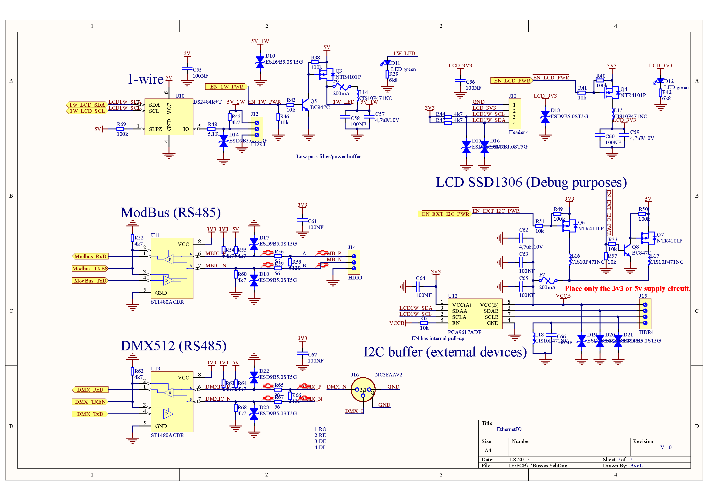
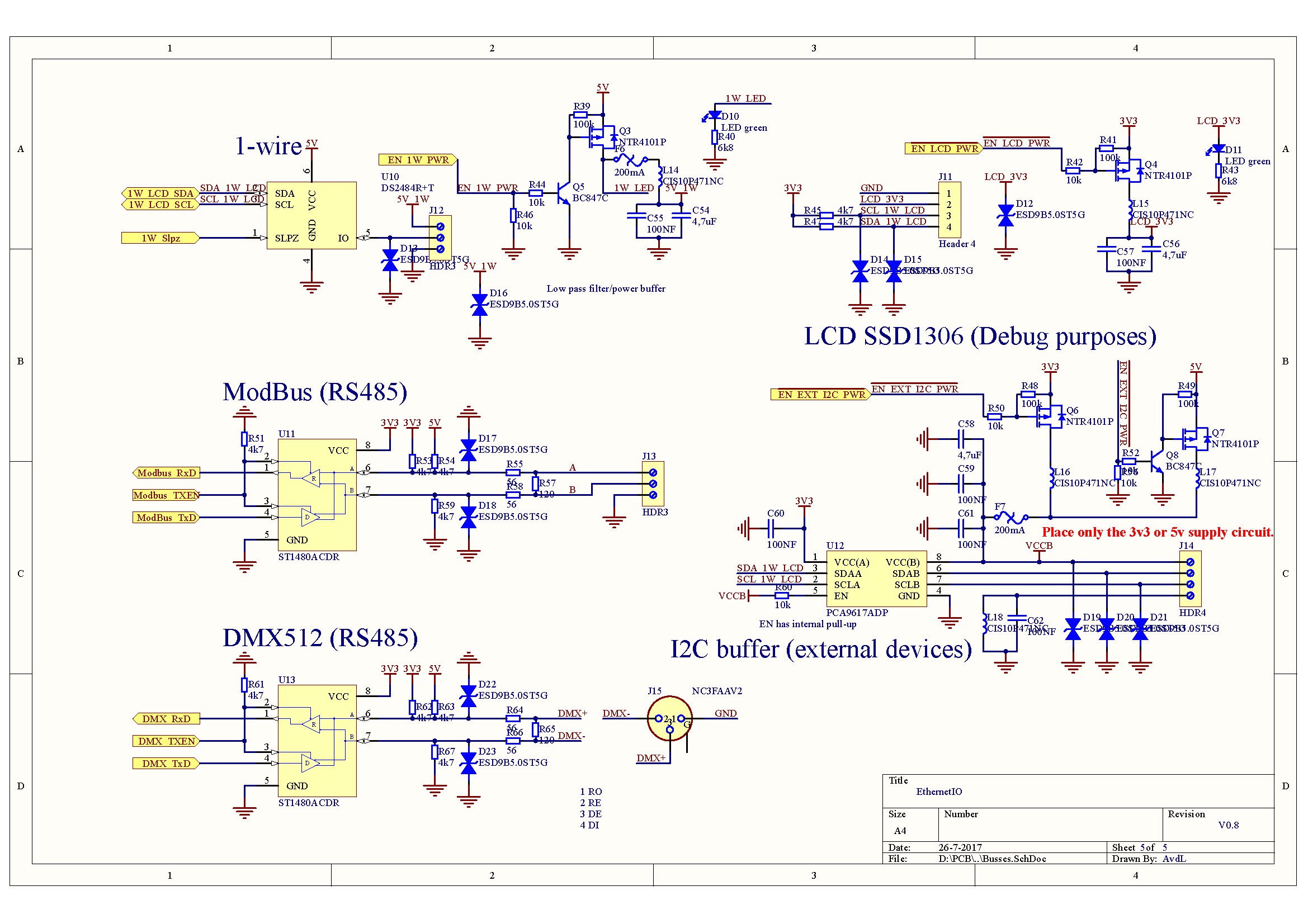
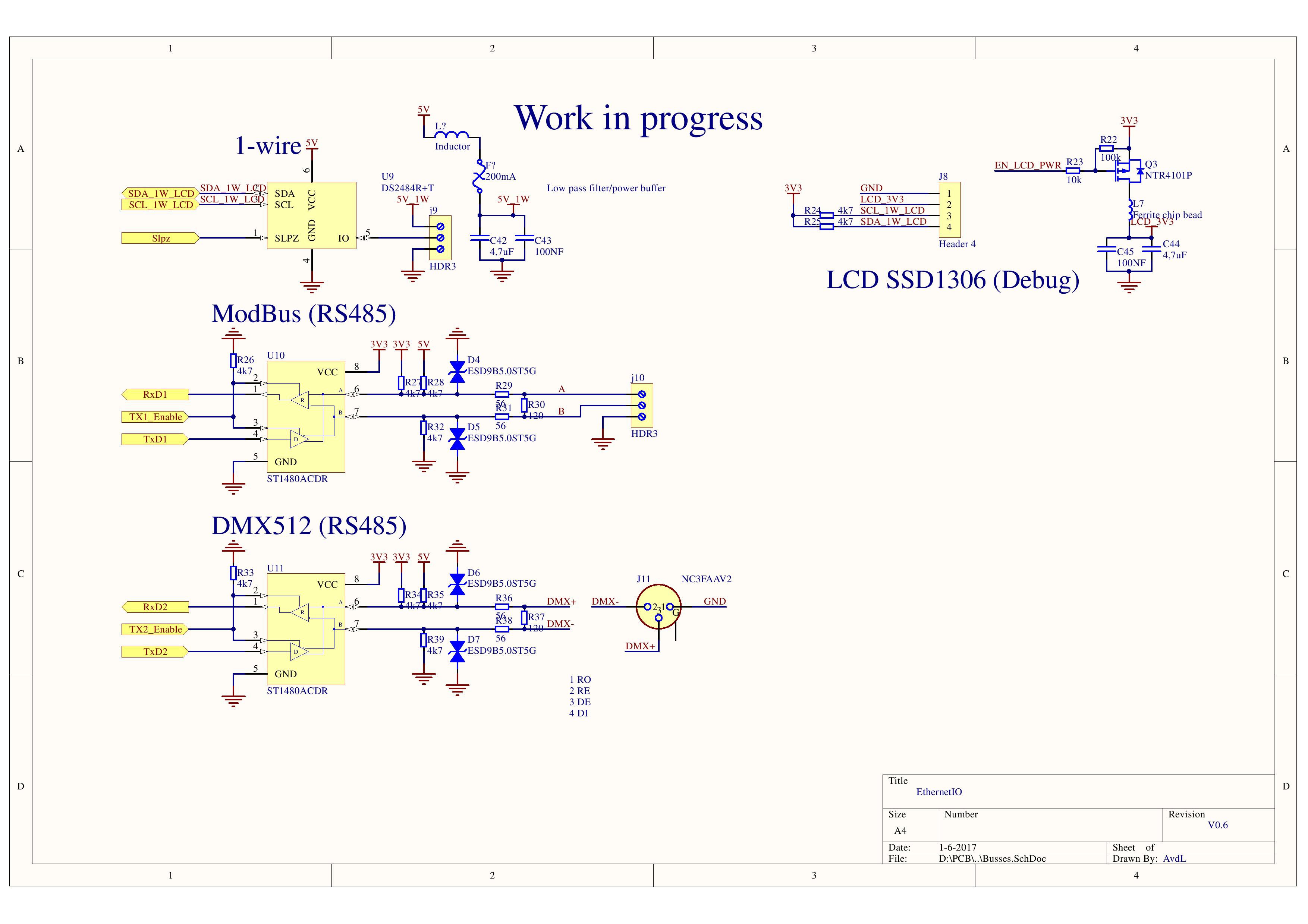
* 1-wire interface. Connected with a DS2484R+T to the ATSAMD21
* Modbus interface. Connected with a MAX485/SP485/ST485 to the ATSAMD21
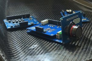
* DMX interface. Connected with a MAX485/SP485/ST485 to the ATSAMD21
* Small LCD to give insight into the working PCB
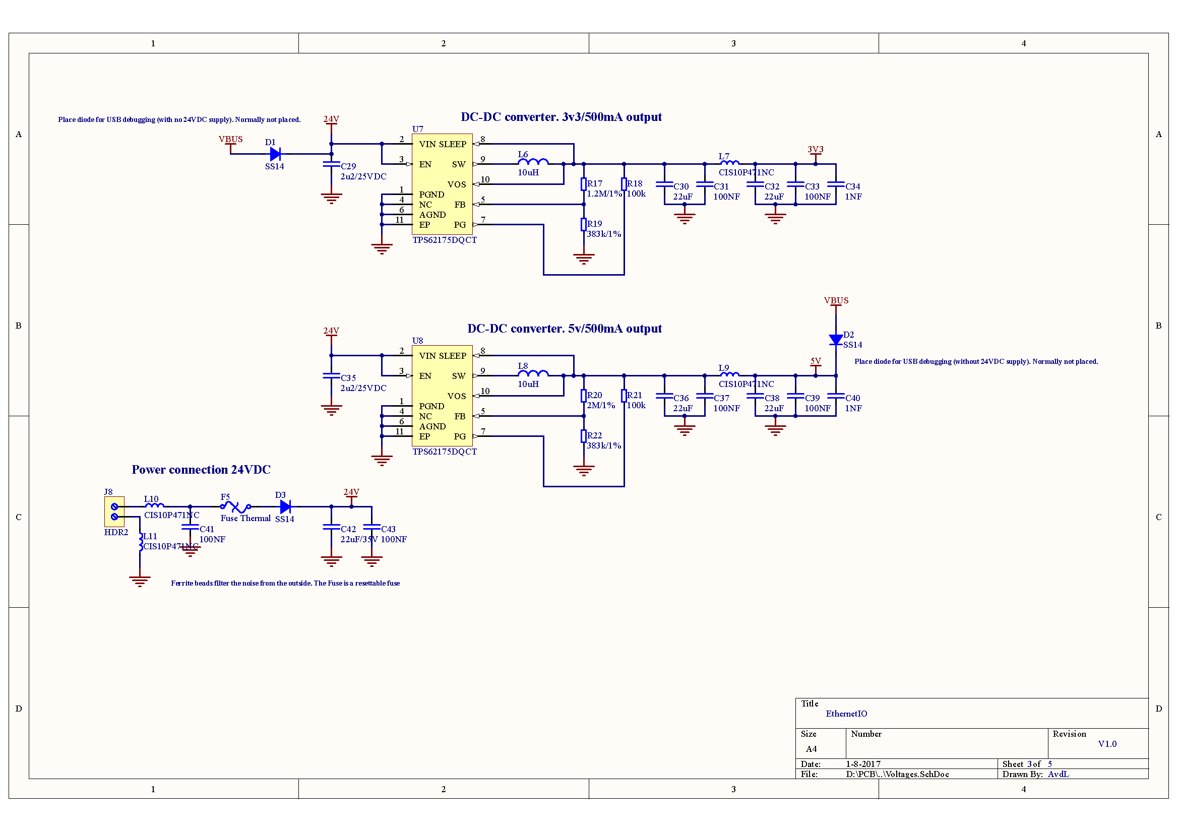
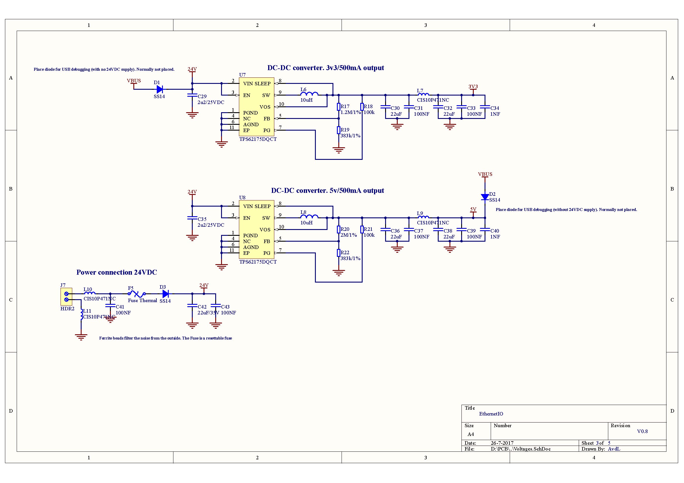
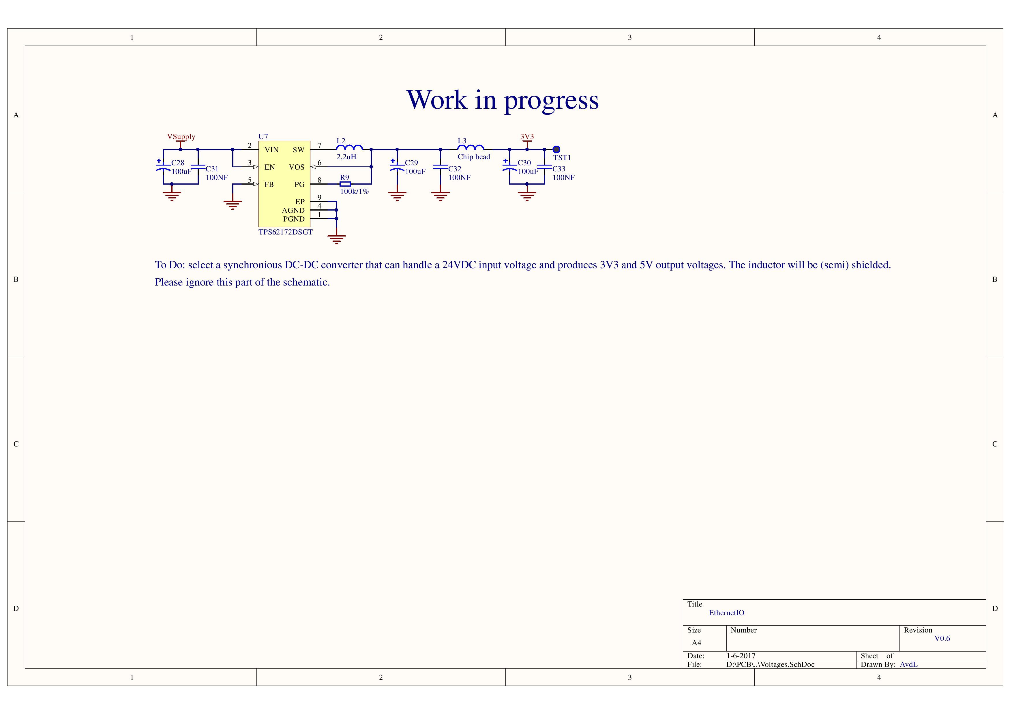
* High efficiency step down power converter. The 24VDC will be converted to 3v3 and 5v for powering the MCU and peripherals.
* Cheap solution. This doesn't mean that the PCB is no good quality. I won't compromise the quality to get a cheaper PCB. The PCB has ESD protection diodes and resettable fuses.
* This PCB will probably spark some other ideas. Modifying sensors and suggestions for sensing the smart home.
The ethernet connection is the main communication possibility of the PCB. There are a lot of Arduino libraries available or the Modbus/1-wire/LCD/BLE, etc. I am a hardware engineer and not specialized in developing software. Please joint me in the open hardware/software project to make it a good PCB. I will use this board for my Loxone, but you can also use it for other home automation systems. It can also support MQTT. But If you want 'just' a PCB that is able to control your house from a remote location (TCPIP IO with a webpage), this is the PCB to make it all come true. The possibilities are limitless. You can also make your PCB custom made. Leave things off the PCB if you don't need them. To all the software engineers....Please joint the project or send me a message.
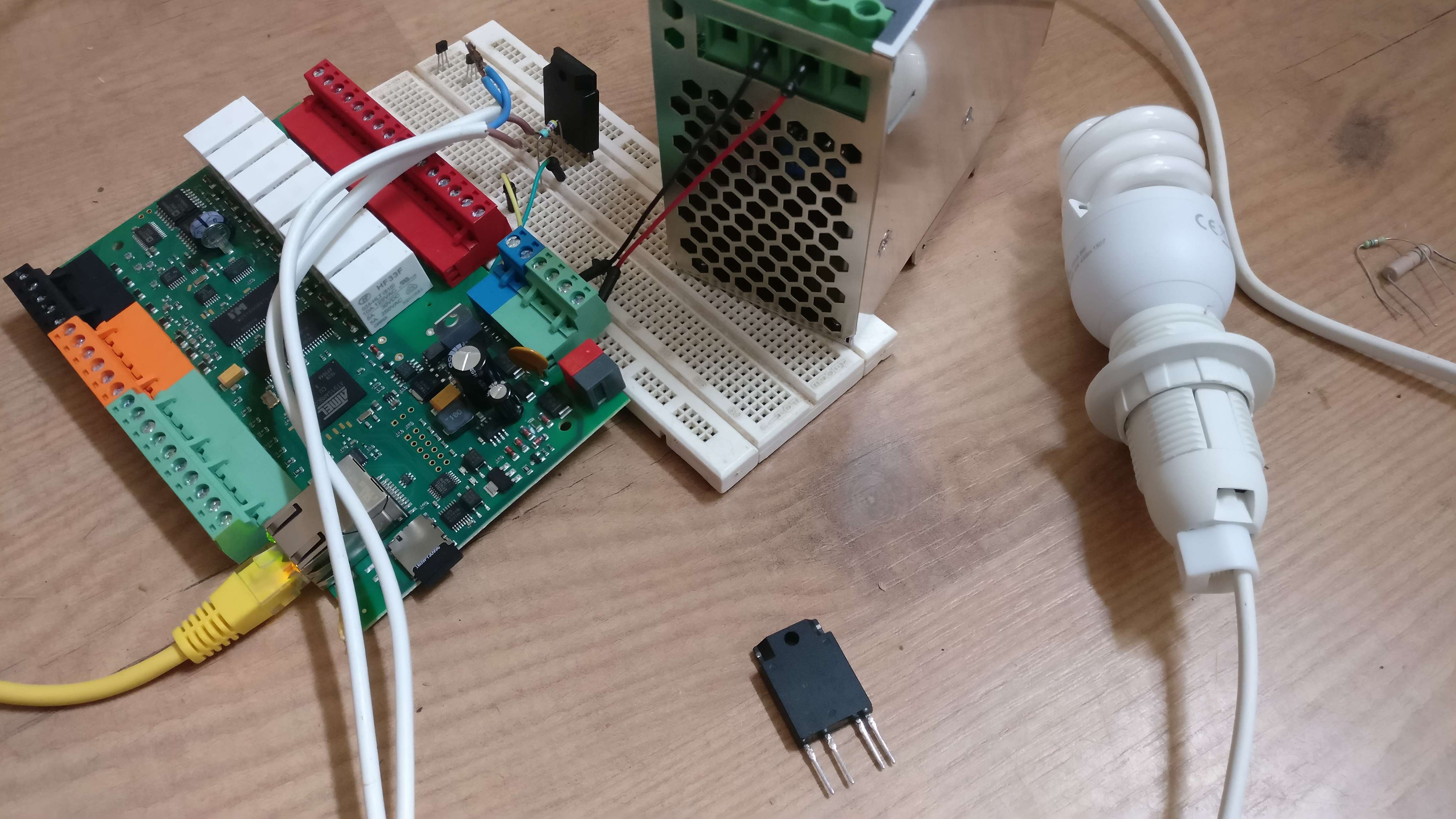
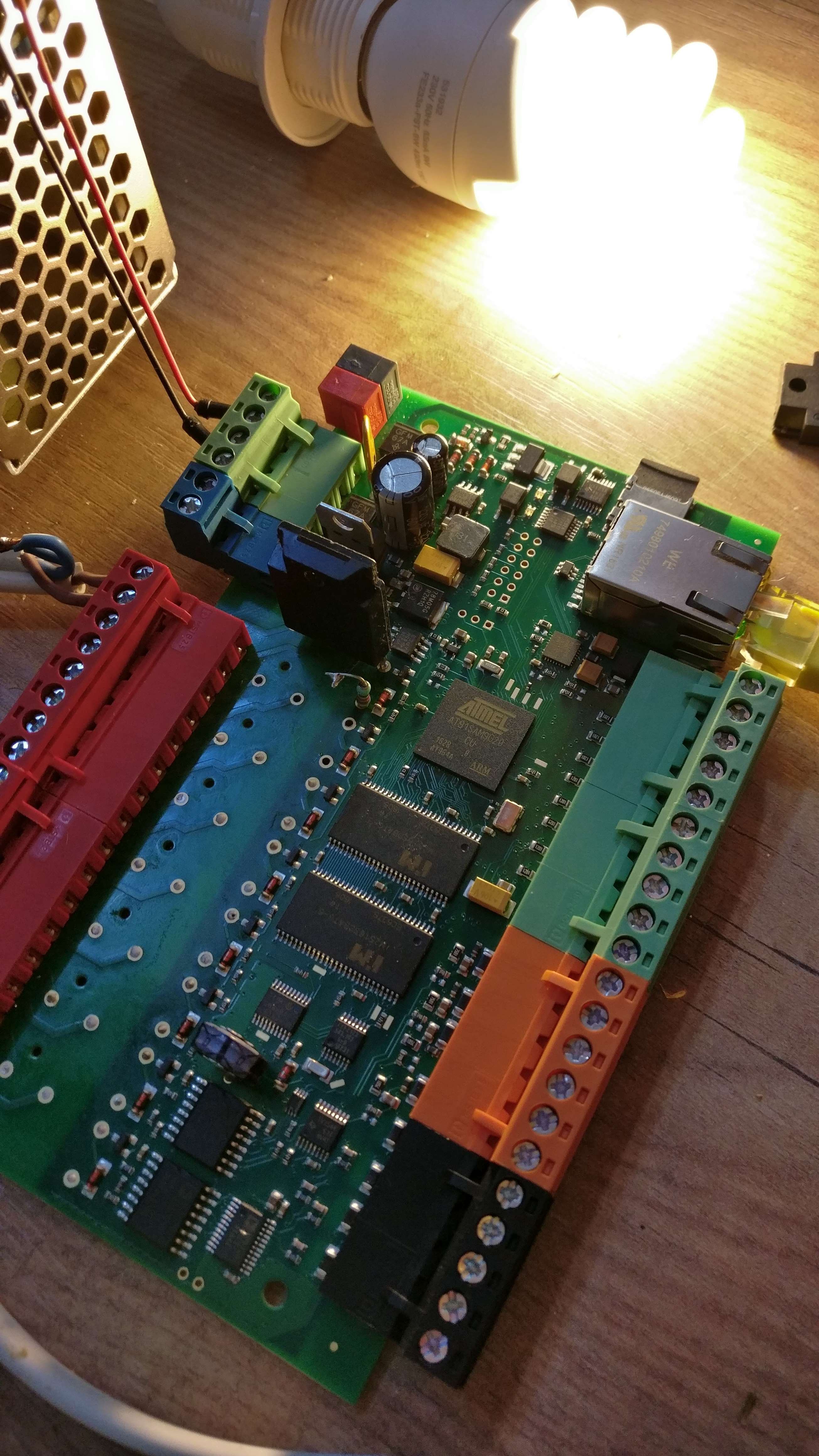
Ps. the picture is of an existing modbus board that has 16 inputs and 14 output relays


 Jithin Sanal
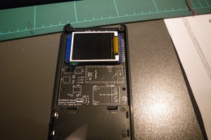
 PUTMotorsport
 DIY GUY Chris