Close
0%
0%

EasyPWR

A small, easy to assemble board that makes use of old wall warts.

Similar projects worth following
This is another mini project that came about because I needed 5V and/or 3.3V for various projects. It makes use of my old wall warts!

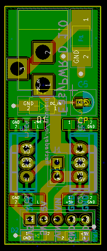
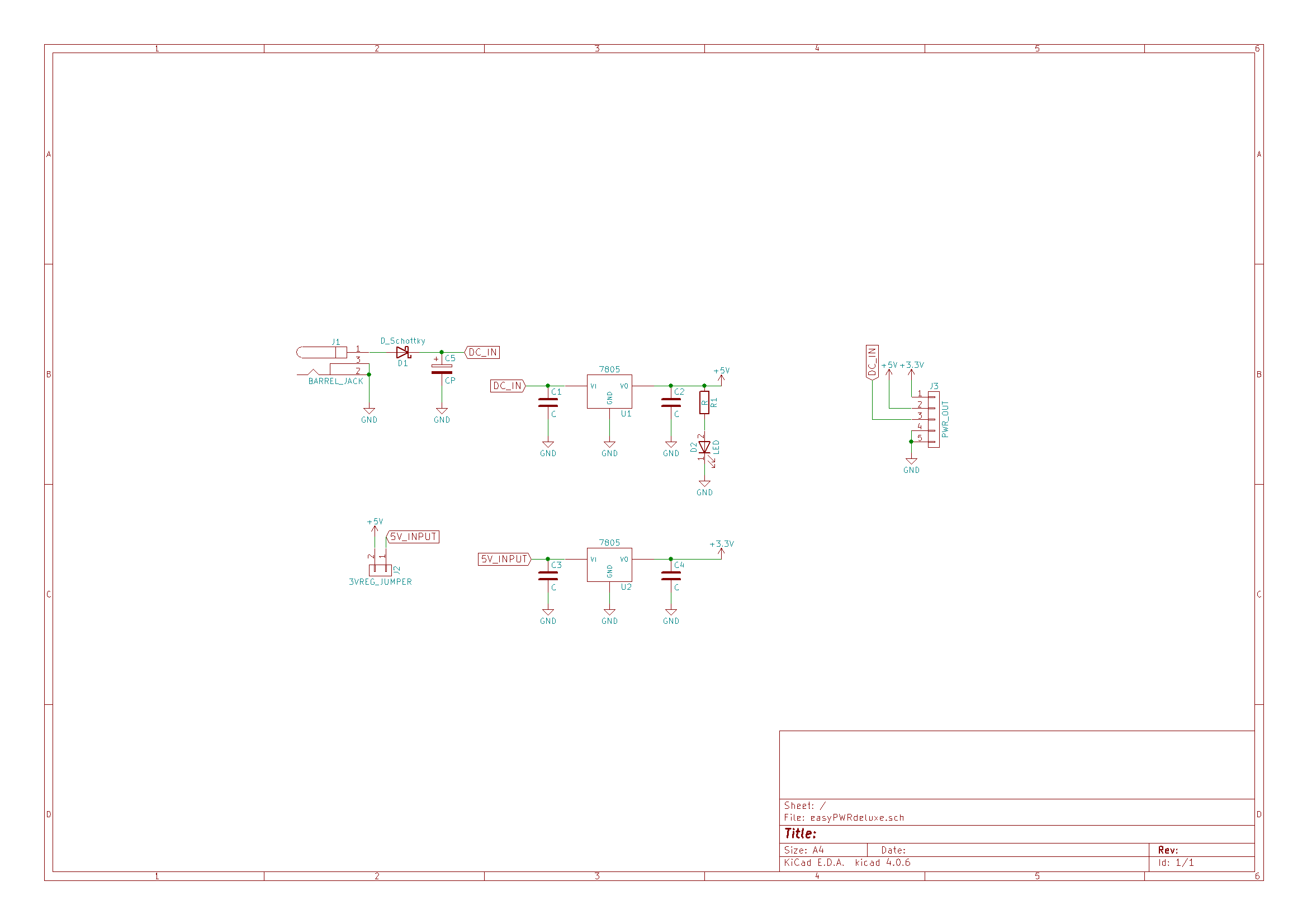
Like many of us, I had a bunch of various wall-warts lying around, but sadly though none of them produced a regulated 5V/3.3V. I had some 78xx regulators around, so I went into KiCad and made a board to make those wall-warts useful! Changing the world by saving old wall warts from the dumpster!

I used one to power my ESP8266. It worked but the linear regulator was unsurprisingly getting a bit warm, especially since I was powering the regular from a 9V wall wart. Not exactly very efficient. I looked into drop-in switching regulator replacements for 78xx linear regulators and found some nice ones made by Murata: the OKI-78SR-5/1.5-W36-C for 5V and the OKI-78SR-3.3/1.5-W36-C for 3.3V. Those regulators make it much more feasible to use with commonly found 9V/12V wall warts to power things such as the ESP8266 that draw a good bit of power.

Switching regulator replacements for 78xx liner regulator offer much better efficiency, but sadly do cost substantially more. The UA7805CKCS, a 5v linear regulator from ti can be had for $.74 in Mouser for a quantity of 1; The OKI-78SR-5/1.5-W36-C a 5v switching regulator is $4.30 on Mouser.


Special notes:

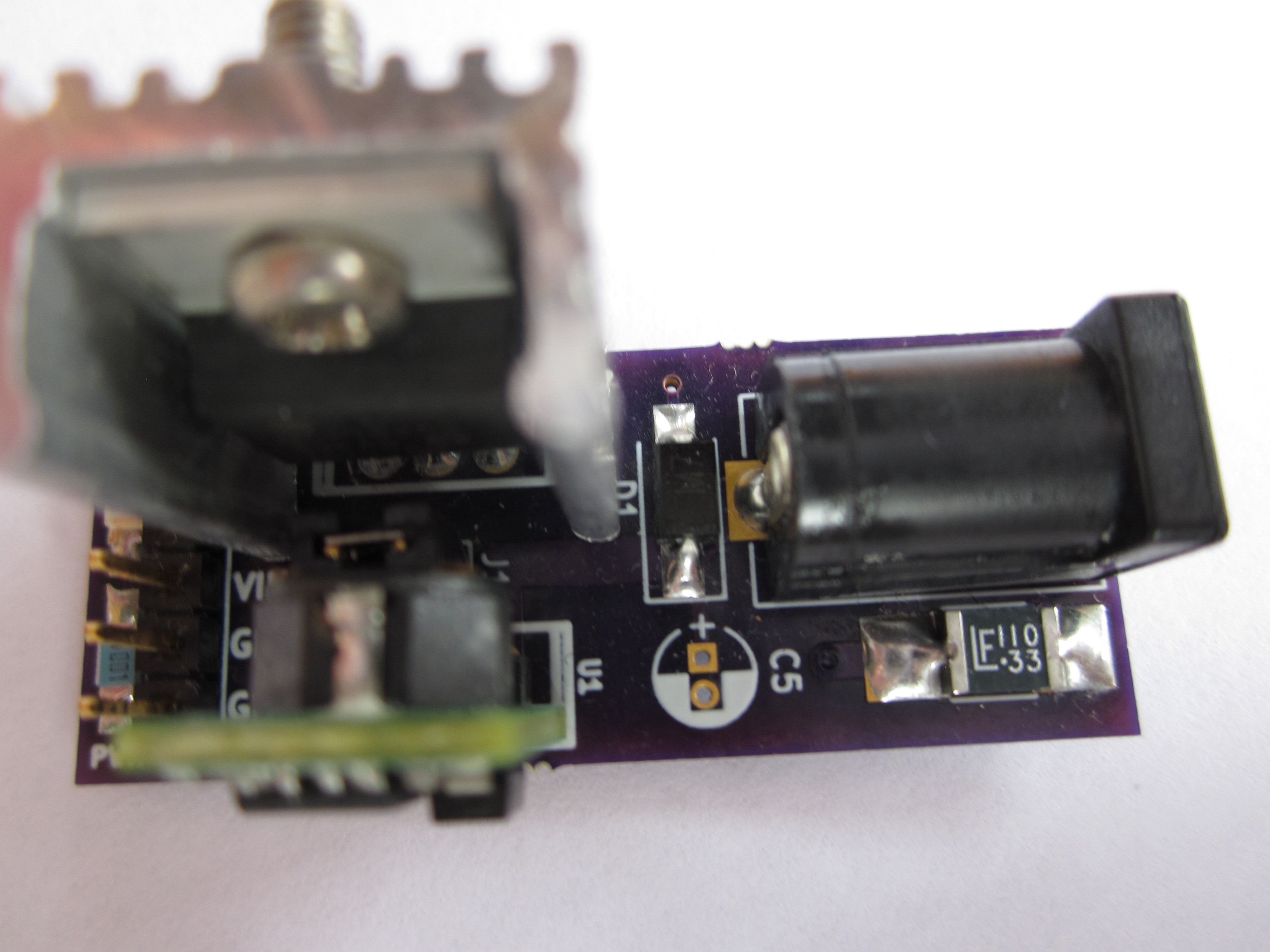
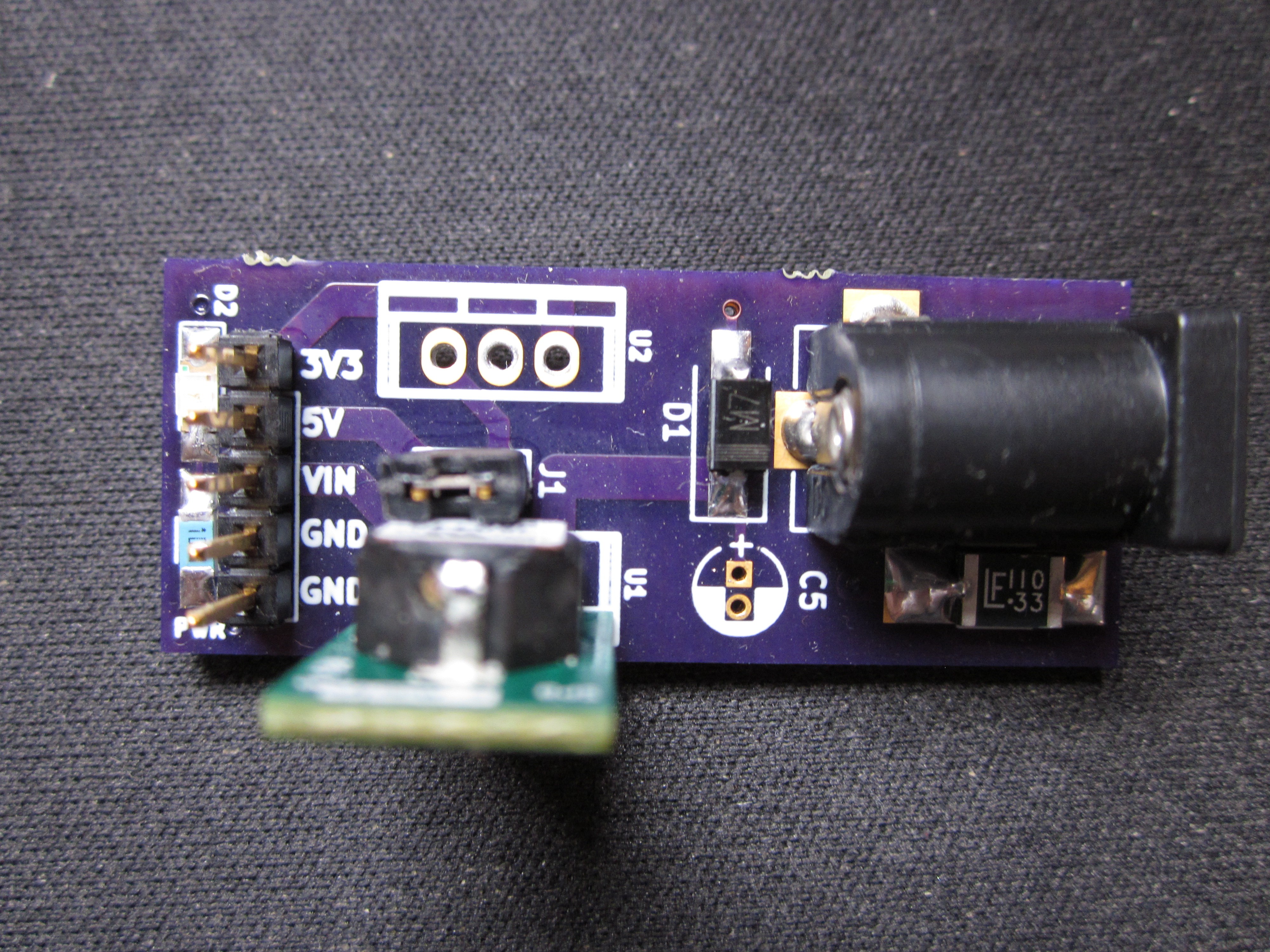
The EasyPWR is designed to be used with wall warts that have center positive barrel plugs.

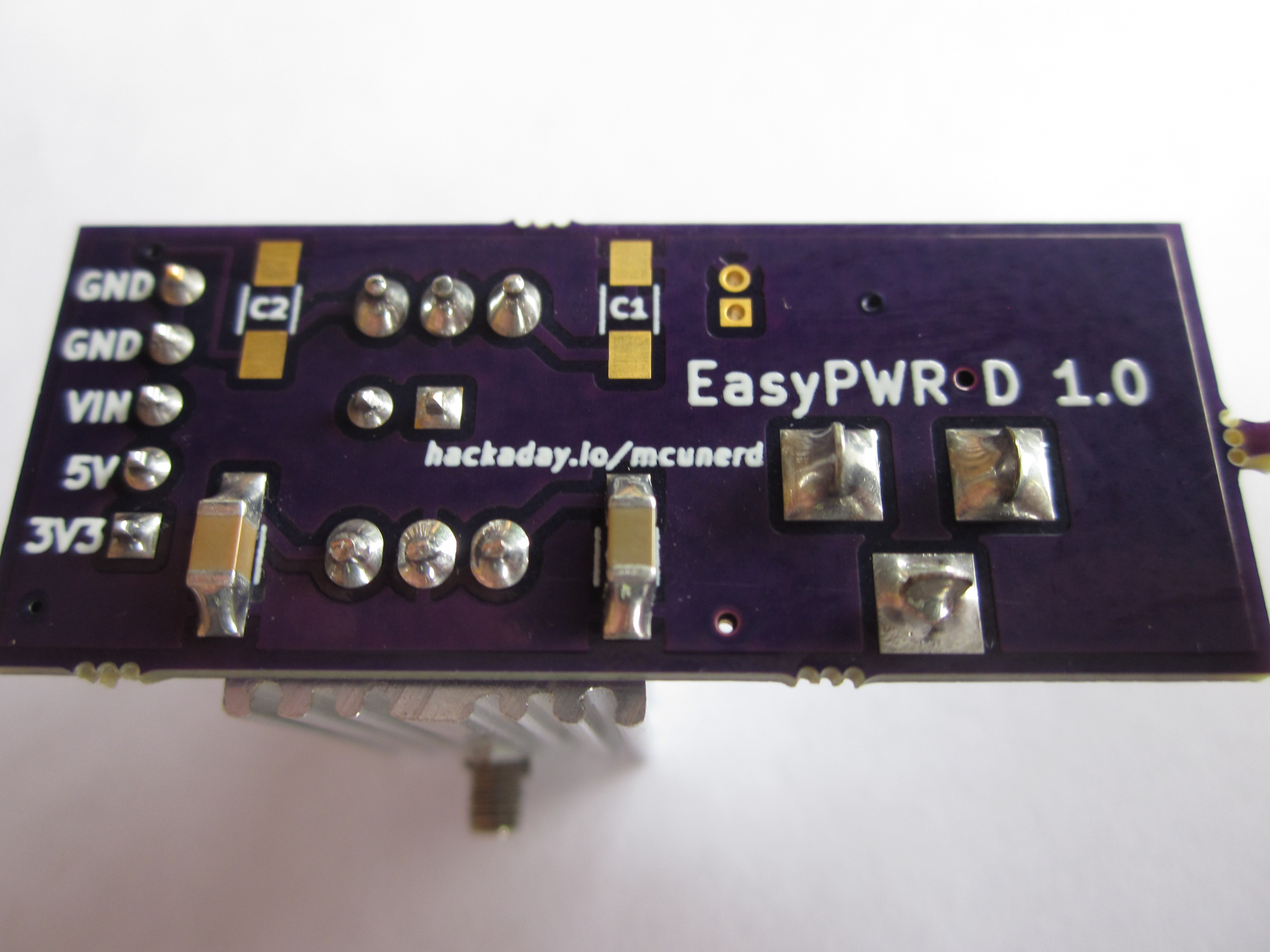
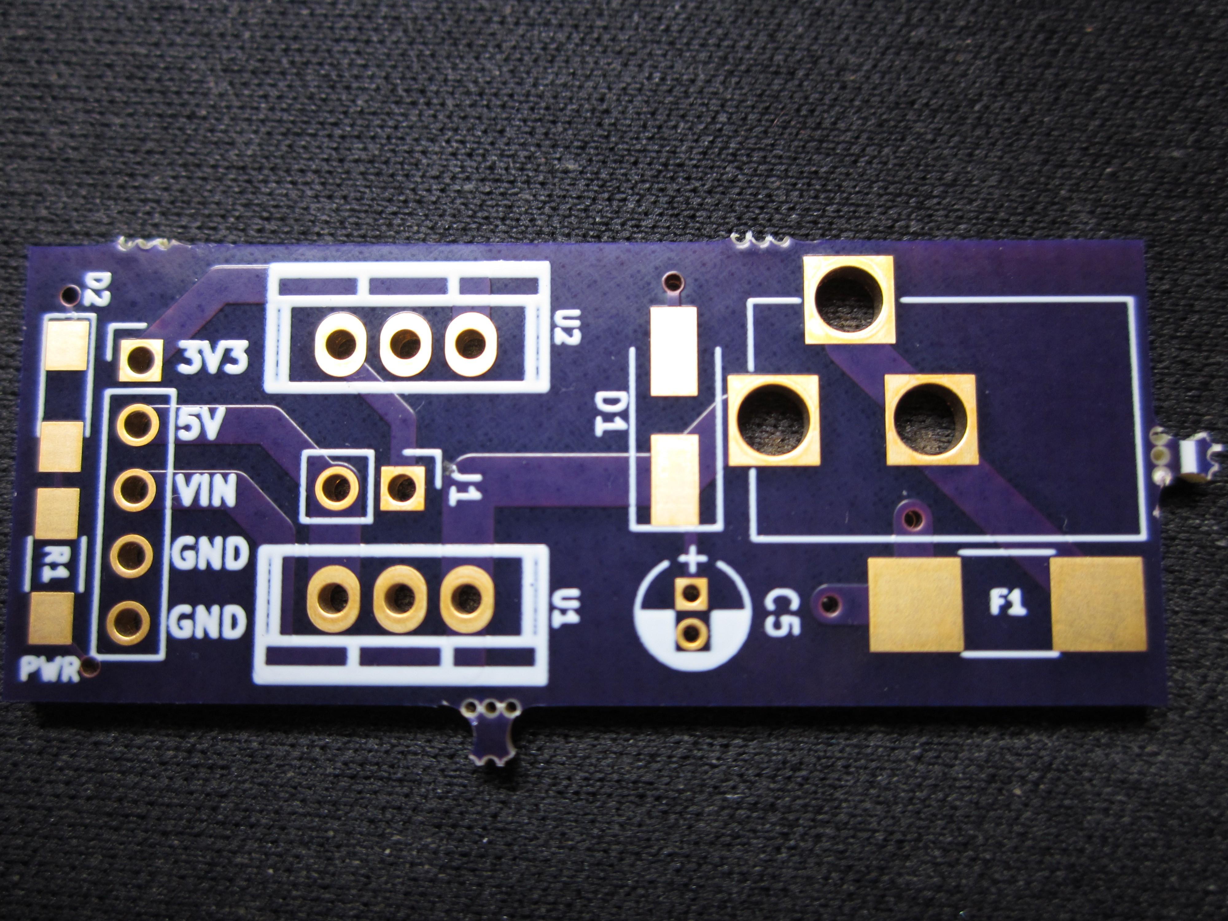
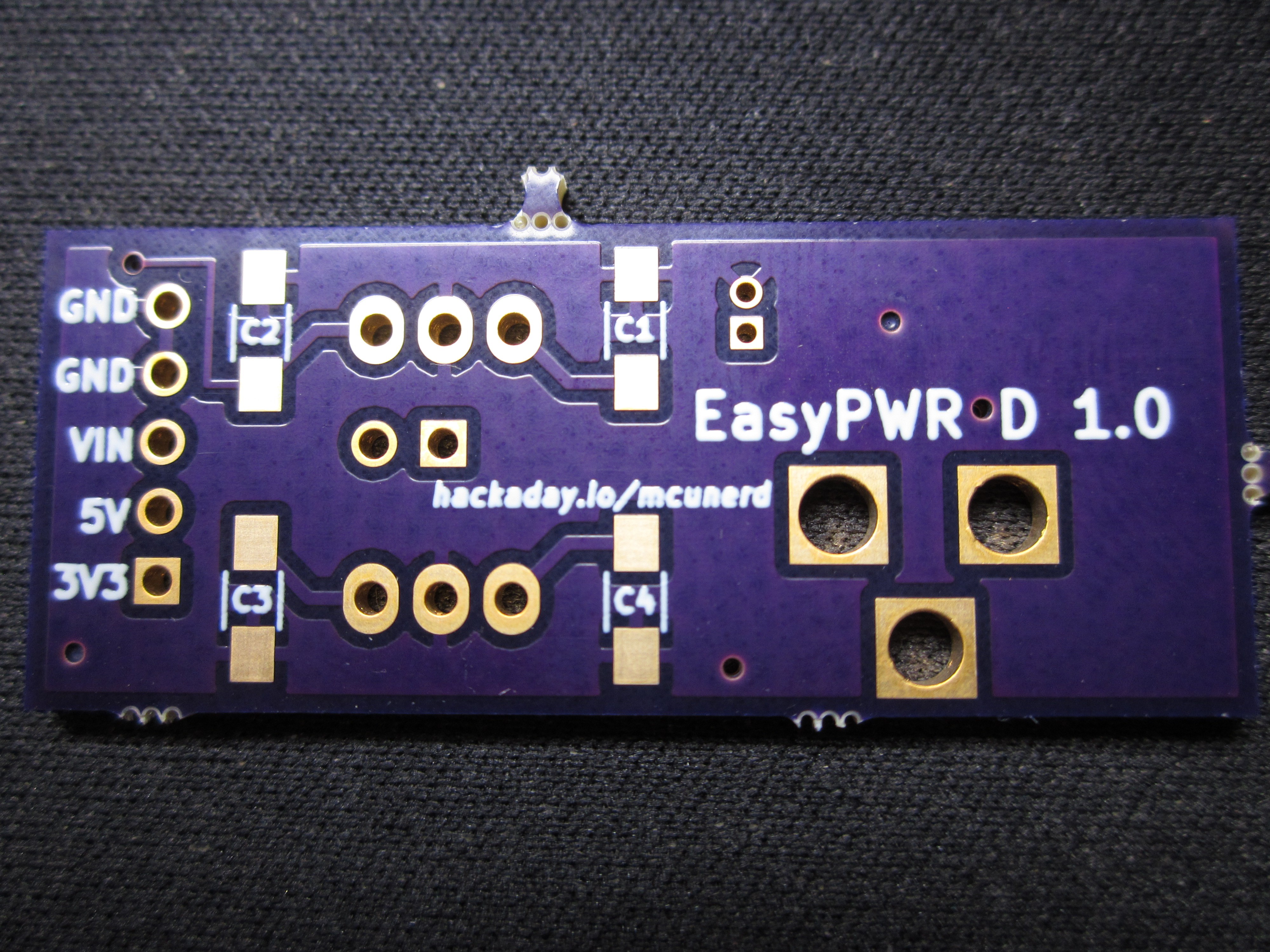
C1 and C2 are 1206 sized pads that should be populated with appropriate value capacitors if using a linear regulator (read the datasheet for recommend values for your model). With switching regulators such as the two models that I mentioned above, the capacitors can usually be left out.

Using the board with a linear regulator is fine to power a typical microcontroller, some LEDs, etc, but if you need to draw say 1 amp of current and your using a 9V/12V wall wart, using a switching regulator is the way to go.

There is a VIN pin to supply power to the board if you are using other than a wall wart for a power source.

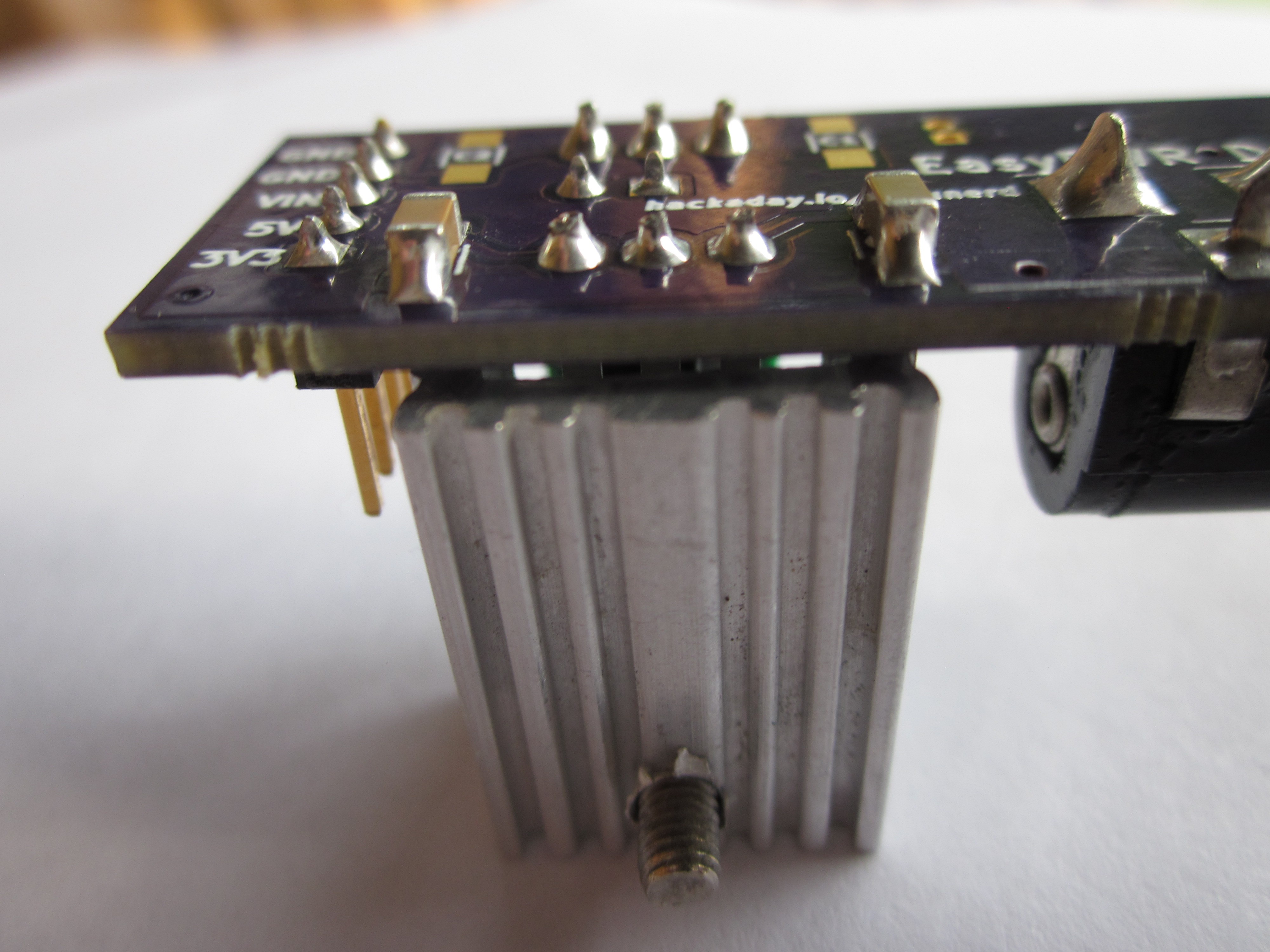
There is some space for a small heatsink, the board is not intended for situations in which alot of heat would be dissapted from the regulator.


All files fall under the GPL v3 license.

easyPWRdeluxe.zip

KiCad project files for the deluxe board.

x-zip-compressed - 76.90 kB - 08/13/2017 at 01:28

Download

easyPWRv2.zip

KiCad project files for the board.

x-zip-compressed - 28.21 kB - 03/24/2017 at 12:49

Download

  • 1 × PCB Electronic Components / Misc. Electronic Components
  • 1 × 4-pin .1" header
  • 1 × 2.1mm DC barrel jack
  • 1 × 78XX regulator or a switching drop in replacement for the 78XX

  • EasyPWR Deluxe build complete

    mcu_nerd09/30/2017 at 17:30 2 comments

    Last week the 1 uF ceramic caps came in, so I was able to finish it on Thursday (would have done it sooner in the week, but had too many other things going on.)  A minor issue that I found is that the 3.3V regulator  sits a little bit higher off the board than other regulators, so my heatsink doesn't make contact with the board.

    The full parts list for the EasyPWR Deluxe:

    1206 sized resistor (recommend a 2K+ value)

    1206 sized LED

    2.1 mm Barrel Jack

    5x1 2.54 mm pin header

    2x1 2.54 mm pin header

    1 pin jumper

    oki-78sr-5/1.5-w36-c 5v regulator (most expensive item other than the PCB itself)

    1812L110/33MR 1812 size polyfuse

    3.3V reg model MCP1825S-3302E/AB

    2 1 uF 1206 caps for the linear regulator (C3 and C4 pads)

    1 TO-220 heatsink

    And of course the photos of the finished product below:

  • Finally selected a regulator for the 3.3v rail

    mcu_nerd09/08/2017 at 18:48 0 comments

    It's about time I selected a regulator for the 3.3V rail.  I've selected the MCP18255-3302E/AB which has an output current rating of 500 mA. I already have the regulator, I'm just waiting on the 1uF ceramic caps to arrive.

  • The Deluxe version board is here!

    mcu_nerd08/13/2017 at 01:20 0 comments

    Sorry for the late post, I've been a bit busy.  I did manage to finish designing the board by the end of the week of the last log. Incoming photos:


    I still haven't come up with the exact model linear regulator to use for the 3.3V rail just yet.  Overall I'm happy with the design so far.  I did add a footprint for an optional electrolytic cap on the input, just in case and I had the board space to spare.  I wanted t to add in a few more things such as some reverse-biased diodes across the outputs of both regulators to provide protection against inductive loads, but I wanted to keep the board size (cost) down.

    If I were to make any changes, I would likely move the "PWR" label close to the actual LED(or just swap around the resistor and LED footprints), possibly move the polyfuse to the input positive terminal vs connecting it to the ground terminal, and increase the resistor value that I used for the LED even more as my LED was still on the bright side when I used a 1K resistor.

    Parts list for the deluxe version:

    1206 sized resistor (recommend a 1K+ value)

    1206 sized LED

    2.1 mm Barrel Jack

    5x1 2.54 mm pin header

    2x1 2.54 mm pin header

    1 pin jumper

    oki-78sr-5/1.5-w36-c 5v regulator (most expensive item other than the PCB itself)

    1812L110/33MR 1812 size polyfuse

    3.3V reg model tba

    caps for the said 3.3V reg tba

  • I'm still here

    mcu_nerd07/25/2017 at 19:16 0 comments

    I've been busy with other things and I've gotten the chance to start working on my projects once again.  I've finally been able to find the magical polyfuse with the voltage and current rating that I've been looking for.  The part isn't expensive, but sadly isn't listed on Ebay (at at reasonable price.) I hope to get a hold of a few via samples. I do plan to finish designing the board this week.

  • Working on the Deluxe version

    mcu_nerd05/25/2017 at 01:46 0 comments

    Ah nothing like having a load of other things distracting me away from the project. Anyways, I recently started working on schematic of the deluxe version. I was first thinking about doing a p-channel MOSFET for reverse polarity protection, but then I wanted something simpler and cheaper. I then thought about doing a reverse-biased diode and fuse. I wanted to use a resettable fuse but didn't find exactly what I was looking for in terms on an inexpensive smd one with a reasonable voltage and current rating.

    I then decided to simply use a Schottky diode but once again I'm browsing Ebay tonight and may settle for a thru-hole resettable fuse. Anyways, here's the last revision of the schematic that I did, sure to change of course.


  • Selecting the best parts for the job for the deluxe version

    mcu_nerd04/29/2017 at 02:25 0 comments

    I haven't done a PCB design yet, I'm still working out the exact components that I plan on using. I found out that the datasheet for the 3.3V linear regulator that I have on hand (ua78m33c) specifies a minimum voltage input slightly greater than 5V. I've had no issues myself with feeding 5V into it, but would prefer to not use a component outside of its recommended specs in the finished product.

  • Back to work soon

    mcu_nerd04/18/2017 at 23:11 0 comments

    Just an FYI, I will be getting back to working on the project again, I've been busy the past two or so weeks with Easter and various outdoor projects that needed to be done before the summer heat kicks in. I hope everybody had a great Easter.

  • Thanks for following/liking

    mcu_nerd04/04/2017 at 12:13 0 comments

    Looks like I'll be designing the deluxe version after all :). I'll likely start working on it in about two or so weeks. I've been busy with varous other projects lately.

    Again, thanks for the support :)

  • Some possible additions for a possible deluxe version

    mcu_nerd03/24/2017 at 19:05 0 comments

    So far the little board has served me well in providing power to my various projects. I've been thinking about doing a deluxe version that could include.

    Two voltage rails, 5V and 3V. A switching regulator could be used for for 5V. An LDO could be used for 3.3V and tied to the output of the 5V regulator, which would make it much more efficient vs using the voltage directly off of the wall wart, so heat dissipation is less of an issue.

    A power indicator LED for one or both rails.

    Reverse-polarity input protection

    Reverse polarity protection (probably using a p channel MOSFET)

View all 9 project logs

Enjoy this project?

Share

Discussions

ted wrote 05/20/2017 at 21:21 point

Are you planning on making this available as a kit of some sort? I'd be happy to help with that- a little Kickstarter or something.

  Are you sure? yes | no

mcu_nerd wrote 05/21/2017 at 00:34 point

Hey Ted, that's an interesting idea. I'm not sure how many folks would be interested but ya never know.  The thought has crossed my mind for my Attiny85 development board that I did last year.

I'm working on the board design for the deluxe version, will make a log update within the next few days.

  Are you sure? yes | no

Similar Projects

Does this project spark your interest?

Become a member to follow this project and never miss any updates