 Quinn
QuinnThe details and steps taken are in the project logs. For easy access, please use this index:
- Concept and Goals
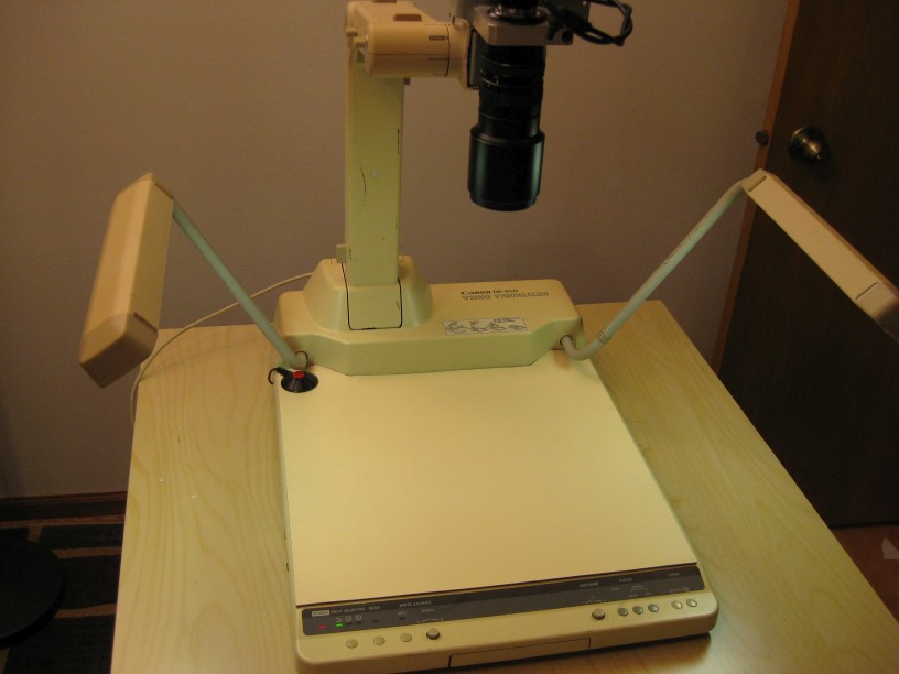
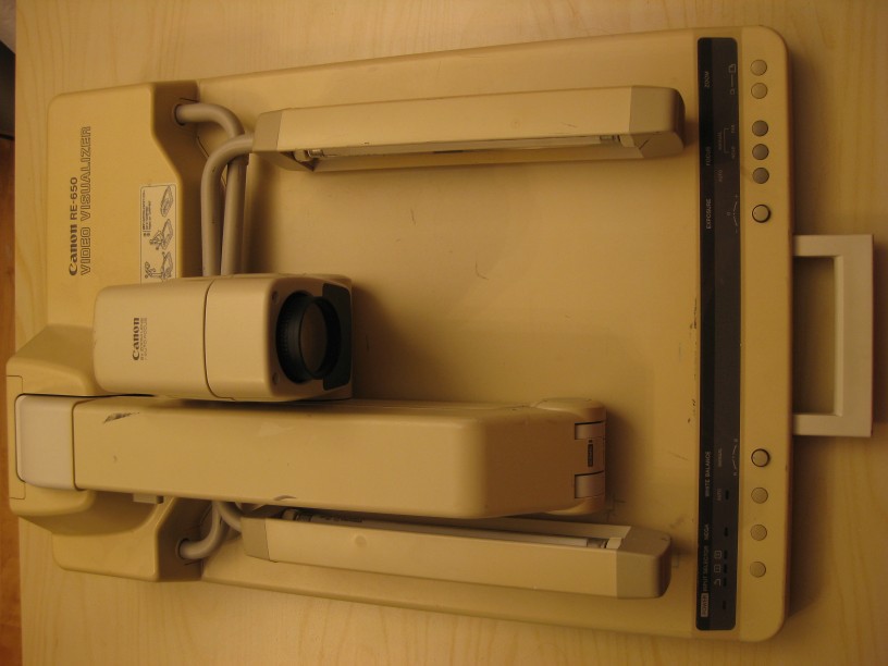
- Video Visualizer (About the original unit)
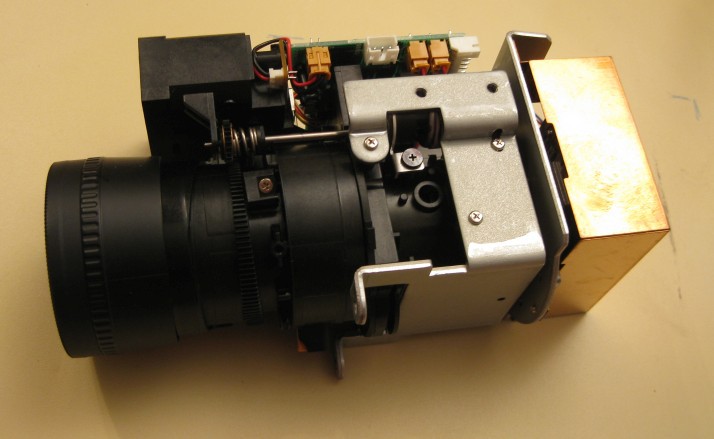
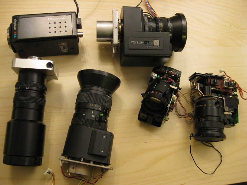
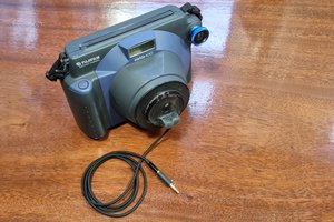
- Camera and Lens Testing (Testing and selecting the lens and camera from parts on hand)
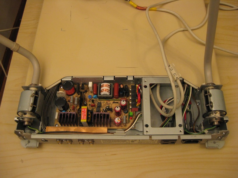
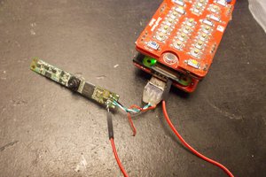
- Inside the RE-650 (A quick look at the parts and boards inside the original unit)
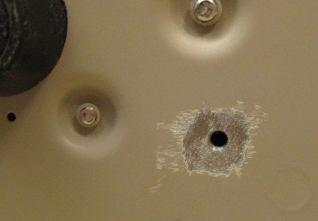
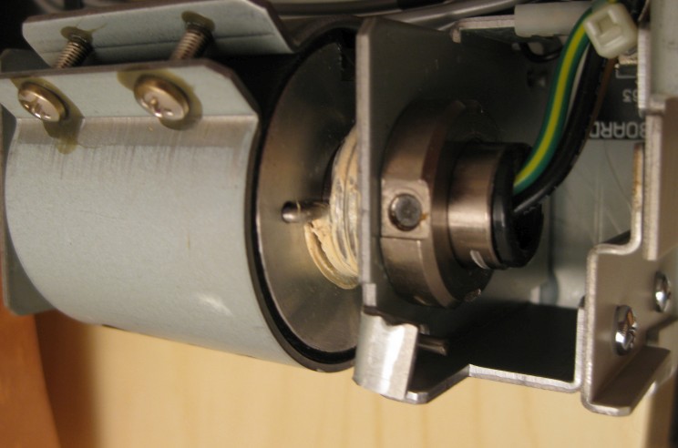
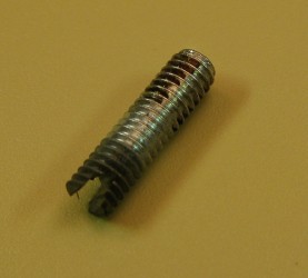
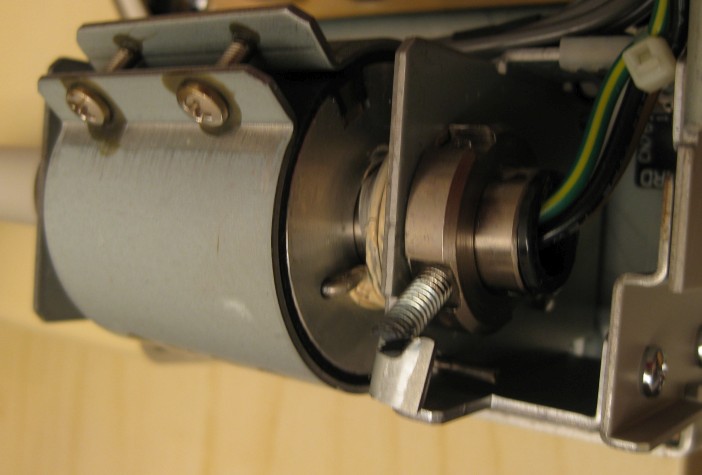
- Fixing the broken light arm (Quick debug and fix of the broken stop post)
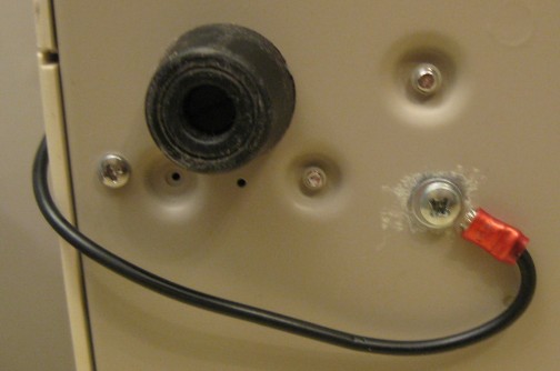
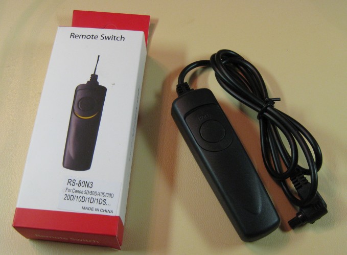
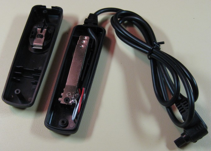
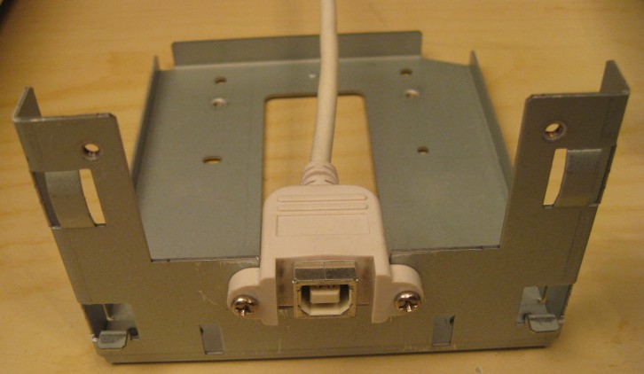
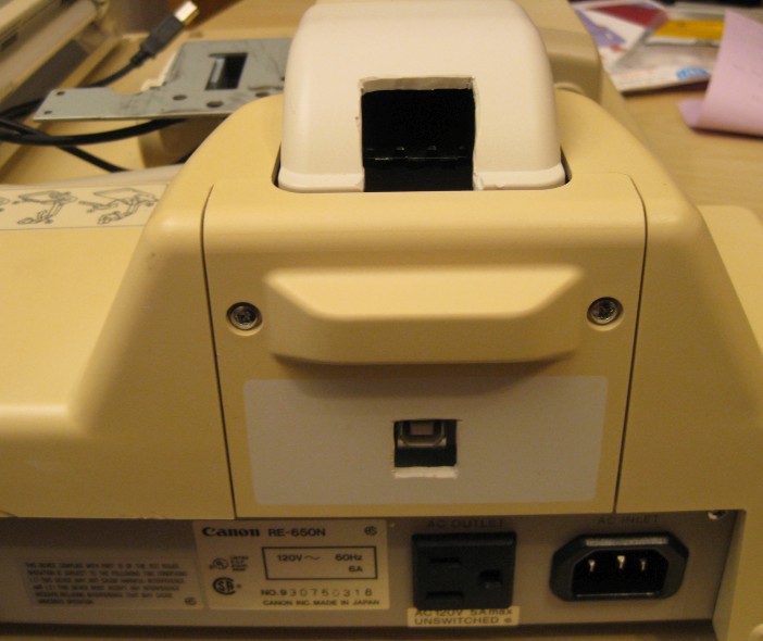
- New wiring and installation (Modifications for the USB and shutter release cables)
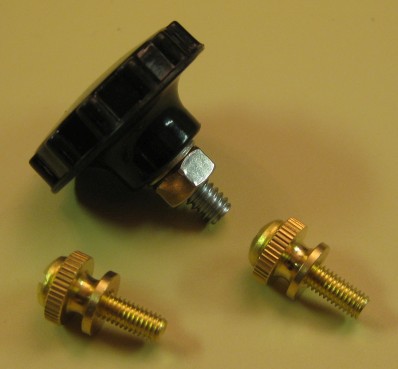
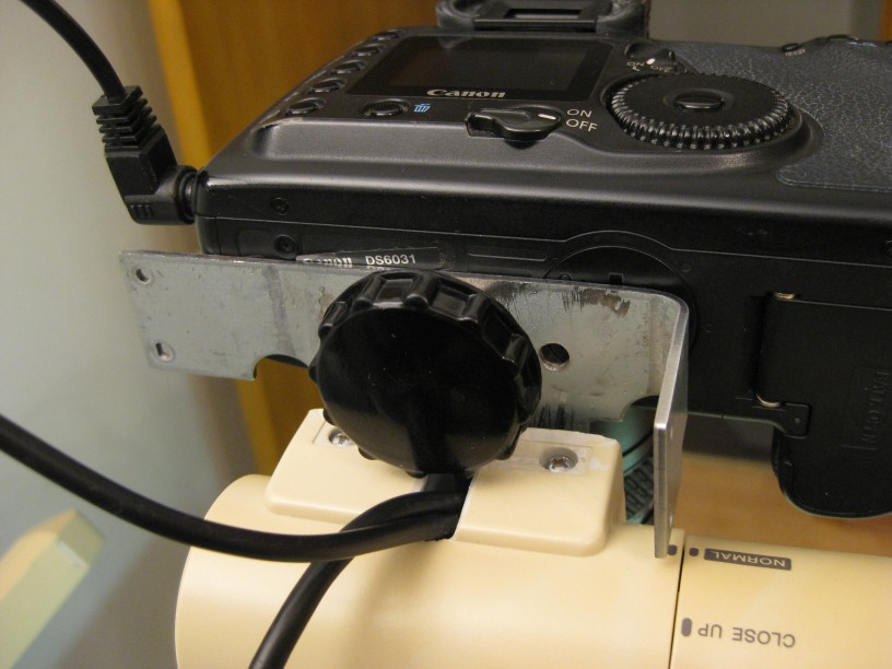
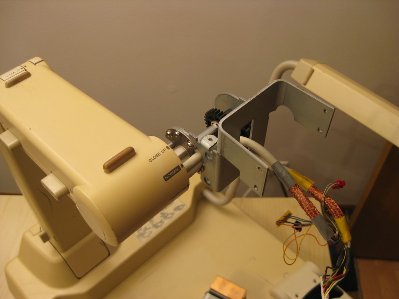
- Camera attachment (Modifying the arm and attaching the cameras)
- ESD mat and grounding (adding a ESD safe work surface for soldering)
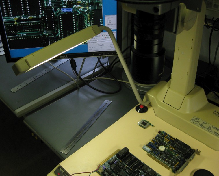
- Finished system (Pictures of the system used in both modes, and folded for storage)
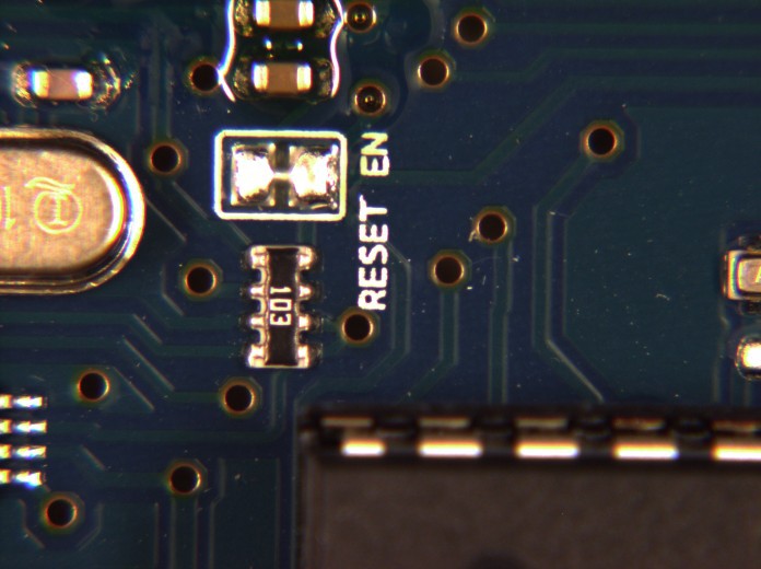
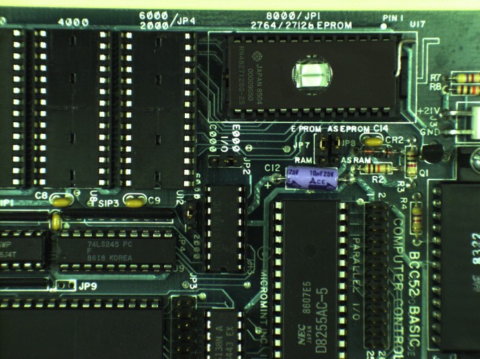
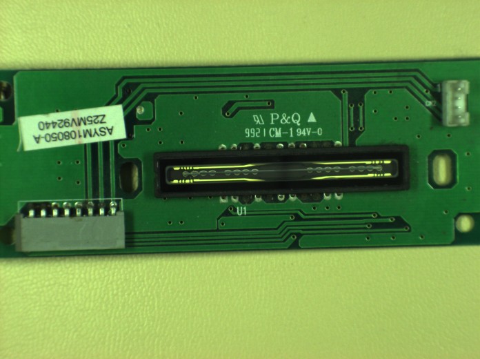
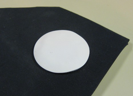
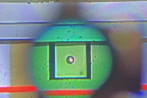
- Sample pictures


 Arya
Arya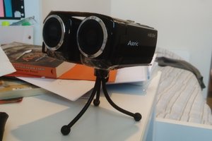
 UnnecessaryComplification