 Adam Gulyas
I started by looking up the optimized logic functions for a full adder, then designed logic gates with relays. I was pretty sure relay logic gates had already been documented, but I wanted to do it myself. Who knows? I might have come up with something new.
Half way through, I realized that the techniques I was coming up with were mirroring the MOSFET circuit topologies for logic gates that I had learned the previous semester. (Pull down resistors! Pass transistor gates!)
I sorted all the circuits by type, shown below:
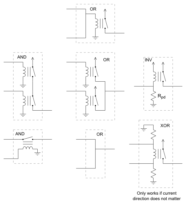
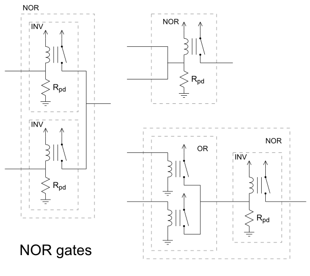
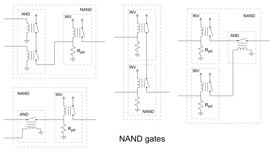
After I had the logic circuits it was simple to chain them together to form the logic functions I wanted.
As it turned out, light L1 and L2 turned out to be directly buffered already. I had to add an extra relay for L3, otherwise input A2 or C2 could have been sent through to power the light. It's probably not a big thing, but I didn't want the power needed for the lightbilb to be flowing through my logic components.
Supply voltage = 12 V
Max current draw < 2 Amps (All the power!)
I would have liked to make a pcb for it, but had to go with perfboard due to time constraints. That rat's nest is the result. Luckily, I was careful enough when soldering that it worked the first time. I would have hated to troubleshoot it.
I also didn't get to put in the power supply. I ended up leaving two banana jacks sticking out the back for a bench top power supply.

 Moritz Walter
 cannoonmaadden
 Yann Guidon / YGDES