Close
0%
0%

Homefixer ESP8266 devboard

A lightweight and simple devboard for ESP8266-12 with 2.54mm breadboard pinout and works with 1V-5.5V batteries

Similar projects worth following
I wanted a simple way to do quick battery powered prototypes with ESP8266-12 that can be hidden away in a small box. So this project is about making a small and beginner friendly devboard with all functions I can think of for doing quick IoT projects so that we can connect everything. Sort of one-click-connect sensor to cloud.
Buy here: https://www.elecrow.com/homefixer-esp8266-devboard.html
Only EU: https://www.tindie.com/products/11245/

Version 1:
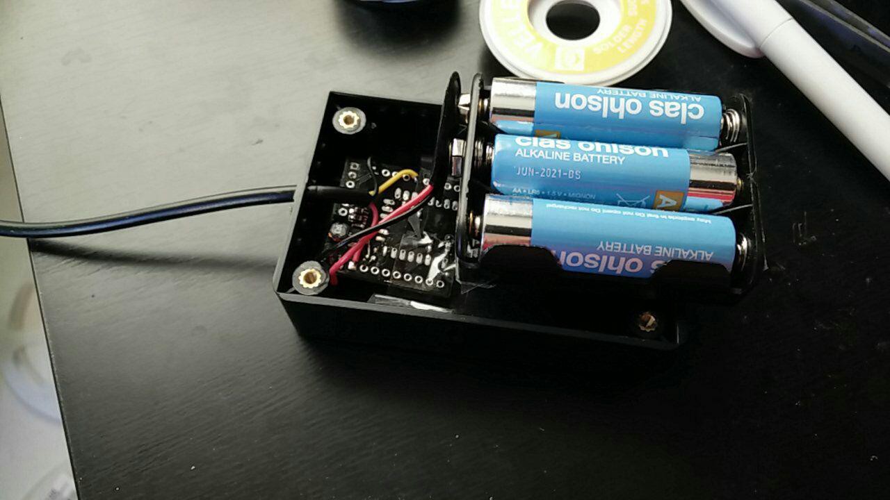
0.5-5.5V power input to be able to run on many kind of batteries using TPS61201.
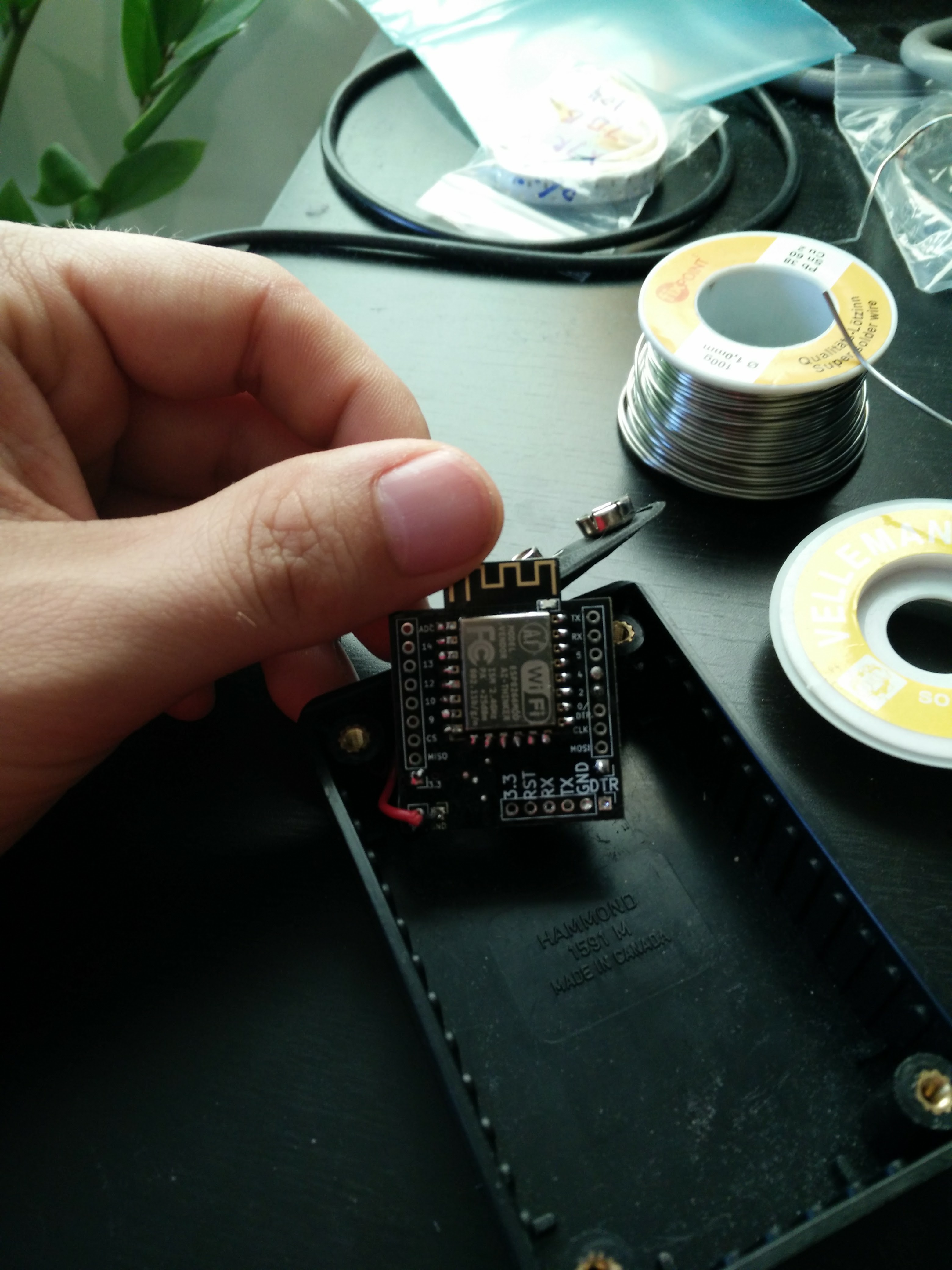
2.54mm pinout of GPIO spaced so it will be easy to put the devboard on a breadboard.
Pullup/down resistors attached for boot, deepsleep, chip enable.
Deepsleep output prewired to reset
ADC connected to a voltage divider from the battery.


Version 2:

  • USB2serial CP2104 with nodemcu based auto reboot to programming mode, power only from USB and not from the battery.
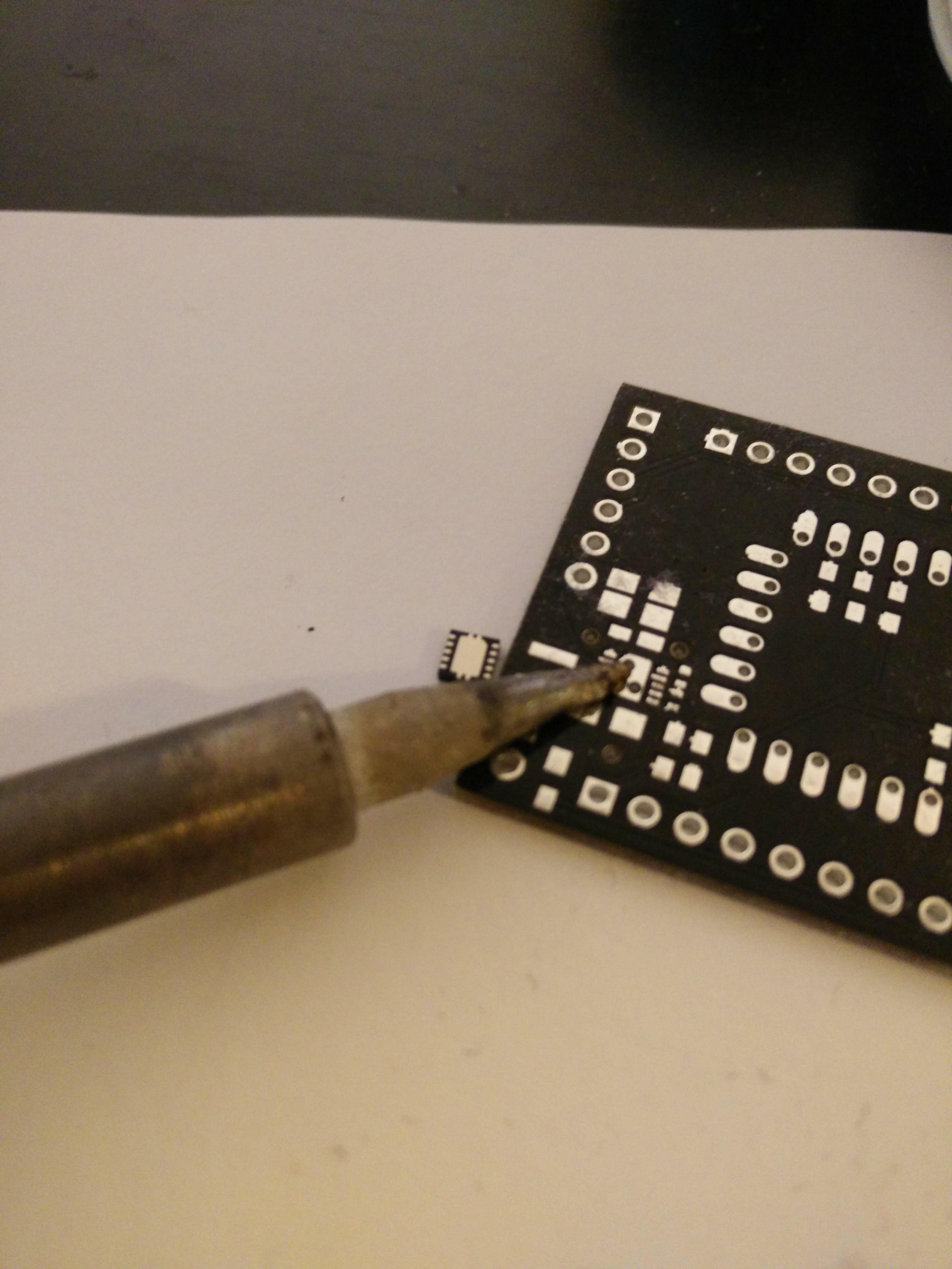
  • Smaller then V1. Compatible with breadboard with the outer most holes free for cables and components.
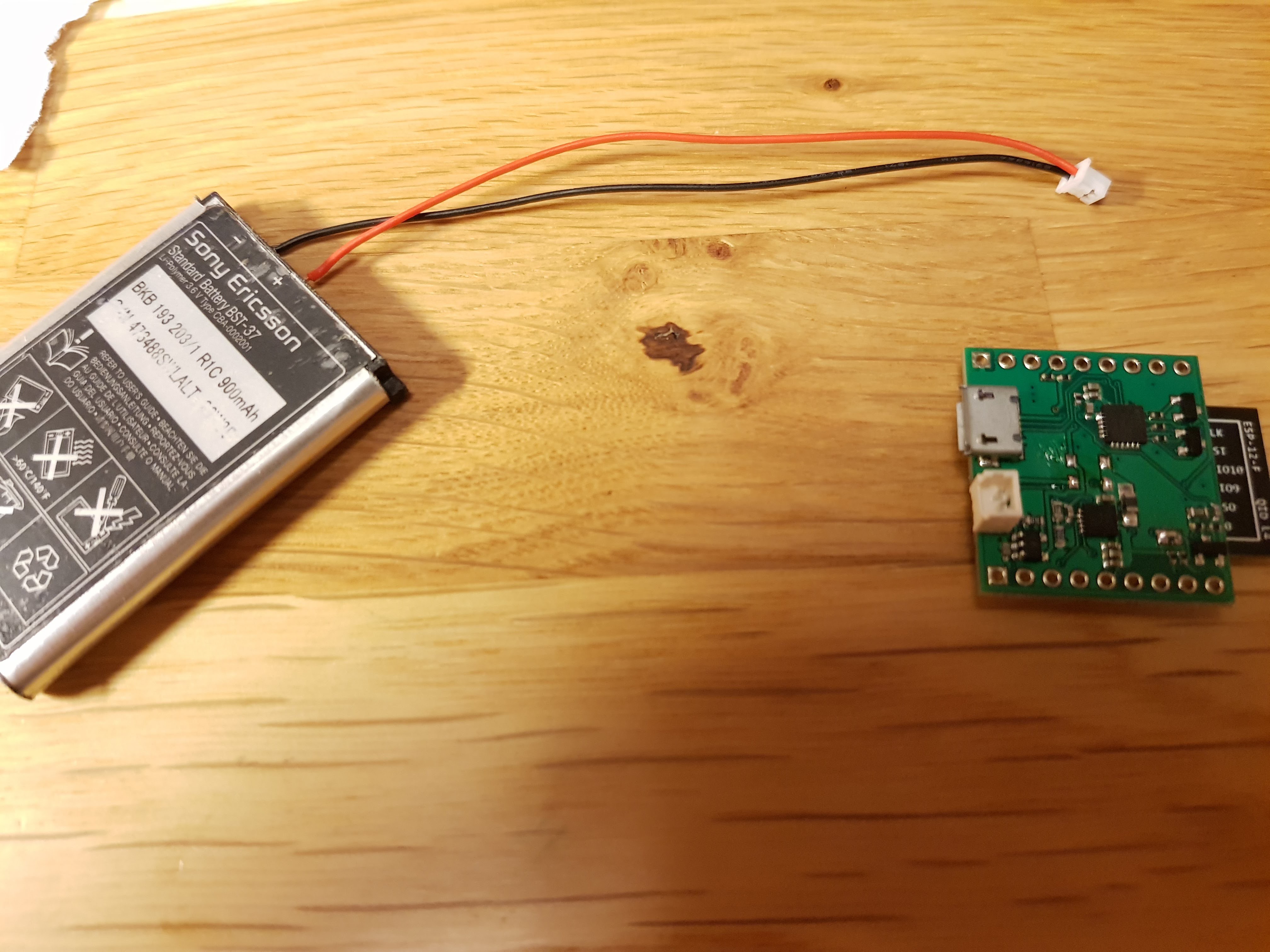
  • LiPo charging (so you can use your old nokia batteries to power your things)
  • TPS61201 3.3V regulator with config pins exposed using solder jumper for settings.
  • Disconnetable ADC measurement of battery for no power use in the voltage divider when not used.

placement.PNG

V1 component placement

Portable Network Graphics (PNG) - 9.33 kB - 01/11/2019 at 13:05

Preview
Download

sheet - 10.08 kB - 04/14/2018 at 13:04

Download

V2_homefixer_esp8266_kicad.zip

KiCad files for the ordered V2.

x-zip-compressed - 888.54 kB - 12/30/2017 at 15:13

Download

gerberfinalv1.zip

Manufacturing files for 3x3 panelized board. Works with seeedstudio

x-zip-compressed - 162.99 kB - 04/05/2017 at 18:48

Download

Adobe Portable Document Format - 67.24 kB - 03/29/2017 at 21:00

Preview
Download

  • 1 × 2k R0603
  • 1 × 10k R0603
  • 1 × 2M R0603
  • 2 × 470 R0402
  • 9 × 10k R0402

View all 17 components

  • Example: DHT11 + mqtt + ThingSpeak

    Johan Westlund01/15/2018 at 21:51 0 comments

    Start by solder deepsleep jumper. (See build instruction)

    Solder the DHT11 to 3.3V, GND and pin 2. You don't need a pullup for pin 2 as it already is placed there for boot-modes.

    Go to thingspeak.com and find your ID and API-key. Also make sure that field 1 and 2 is active.


    Change ssid, pass, id and apikey for your settings:

    #include <ESP8266WiFi.h>
    #include <PubSubClient.h> // MQTT
    #include <SimpleDHT.h> // DHT 11 sensor
    
    #define sleepTimeS 600 //10 min Time between updates 
    // --- PINOUT ---
    const int temp_sensor_pin = 2;
    
    const char* ssid = "ssid";
    const char* password = "pass";
    const char* mqtt_server = "mqtt.thingspeak.com";
    String temperature_topic = "channels/id/publish/fields/field1/apikey";
    String humidity_topic = "channels/id/publish/fields/field2/apikey";
    
    WiFiClient espClient;
    PubSubClient client(espClient);
    long lastMsg = 0;
    char msg[50];
    int value = 0;
    byte temperature;
    byte humidity;
    SimpleDHT11 temp_sensor_obj;
    
    void setup() {
      
      //Wifi
      WiFi.begin(ssid, password);
      int wifiTryConnectCounter = 0;
      while (WiFi.status() != WL_CONNECTED)
      {
        delay(500);
        wifiTryConnectCounter++;
        if (wifiTryConnectCounter >= 10) //Try to connect 10 times or go to sleep
        {
          ESP.deepSleep(sleepTimeS * 1000000);
        }
      }
      
      //MQTT
      client.setServer(mqtt_server, 1883);   
      // Create a random client ID
      String clientId = "ESP8266Client-";
      clientId += String(random(0xffff), HEX);
      // Attempt to connect
      if (client.connect(clientId.c_str())) {
        //Success
      } else {
        ESP.deepSleep(sleepTimeS * 1000000);
      }
      
      //Sensor
      int err = SimpleDHTErrSuccess;
      if ((err = temp_sensor_obj.read(temp_sensor_pin, &temperature, &humidity, NULL)) != SimpleDHTErrSuccess) {
        ESP.deepSleep(sleepTimeS * 1000000);  
      }
      
      //Send
      snprintf (msg, 75, "%ld", (int)temperature);
      client.publish(temperature_topic.c_str(), msg);
      snprintf (msg, 75, "%ld", (int)humidity);
      client.publish(humidity_topic.c_str(), msg);
    
      //Sleep and repeat
      client.loop(); // MQTT work
      ESP.deepSleep(sleepTimeS * 1000000);
    }
    
    void loop() {
      // Will not run
    }

    Upload to the board and enjoy the temperature graph in thingspeak :)

  • Example: Undervoltage alert in Telegram

    Johan Westlund01/11/2018 at 20:14 0 comments

    Preparation:

    Here is an example code for node-red for Undervoltage alert to Telegram.

    You need to add:

    *A bot to the sender node,

    *Put the text you want to be sent out in the text node,

    *Add chatid in conversation node: https://firstwarning.net/vanilla/discussion/4/create-telegram-bot-and-get-bots-token-and-the-groups-chat-id

    *Your topic and Broker to the MQTT node.

    • [
          {
              "id": "a0b2ef4c.ac08d",
              "type": "mqtt in",
              "z": "4e61ffbd.293758",
              "name": "",
              "topic": "device_topic/voltage",
              "qos": "2",
              "broker": "74f4f305.79b8e4",
              "x": 210,
              "y": 179,
              "wires": [
                  [
                      "2838f77a.391648"
                  ]
              ]
          },
          {
              "id": "2838f77a.391648",
              "type": "function",
              "z": "4e61ffbd.293758",
              "name": "",
              "func": "\n \nvar voltage = parseInt(msg.payload) / 1000;\n\nvar msg = {payload:voltage}\n\nreturn msg;",
              "outputs": "1",
              "noerr": 0,
              "x": 396,
              "y": 179,
              "wires": [
                  [
                      "d899ef9c.f29bf8"
                  ]
              ]
          },
          {
              "id": "e695c610.d8b18",
              "type": "chatbot-telegram-send",
              "z": "4e61ffbd.293758",
              "bot": "cfed462d.fcf59",
              "track": false,
              "parseMode": "",
              "outputs": 0,
              "x": 1112,
              "y": 179,
              "wires": []
          },
          {
              "id": "19c9b344.512d35",
              "type": "chatbot-message",
              "z": "4e61ffbd.293758",
              "name": "",
              "message": [
                  {
                      "message": "Battery under 3.3V on unit XYZ"
                  }
              ],
              "answer": false,
              "track": false,
              "x": 914,
              "y": 178,
              "wires": [
                  [
                      "e695c610.d8b18"
                  ]
              ]
          },
          {
              "id": "57bb9322.d0eb8c",
              "type": "chatbot-conversation",
              "z": "4e61ffbd.293758",
              "name": "",
              "chatId": "",
              "transport": "telegram",
              "messageId": "",
              "contextMessageId": false,
              "store": "",
              "x": 748,
              "y": 178,
              "wires": [
                  [
                      "19c9b344.512d35"
                  ]
              ]
          },
          {
              "id": "d899ef9c.f29bf8",
              "type": "falling-edge",
              "z": "4e61ffbd.293758",
              "name": "",
              "threshold": "3.3",
              "x": 559,
              "y": 178,
              "wires": [
                  [
                      "57bb9322.d0eb8c"
                  ]
              ]
          },
          {
              "id": "74f4f305.79b8e4",
              "type": "mqtt-broker",
              "z": "",
              "broker": "localhost",
              "port": "1883",
              "clientid": "",
              "usetls": false,
              "compatmode": true,
              "keepalive": "60",
              "cleansession": true,
              "willTopic": "",
              "willQos": "0",
              "willPayload": "",
              "birthTopic": "",
              "birthQos": "0",
              "birthPayload": ""
          },
          {
              "id": "cfed462d.fcf59",
              "type": "chatbot-telegram-node",
              "z": "",
              "botname": "",
              "usernames": "",
              "polling": "1000",
              "log": ""
          }
      ]

     
    Arduino code:

    Basic work: Wifi connect -> MQTT Broker connect -> Measure Voltage -> Send Voltage over MQTT -> deep sleep "sleepTimsS" seconds

    #include <ESP8266WiFi.h>
    #include <PubSubClient.h> // MQTT
    
    #define sleepTimeS 600 //Time between updates
    
    // CHANGE
    const char* ssid = "ssid";
    const char* password = "pass";
    const char* mqtt_server = "IP";
    String device_topic = "your_topic";
    float cal_volt = 6.85; // Calibrate this value if the voltage reading is of
    
    String voltage_topic = device_topic+"/voltage";
    
    WiFiClient espClient;
    PubSubClient client(espClient);
    long lastMsg = 0;
    char msg[50];
    int value = 0;
      
    void setup() {
      pinMode(15, OUTPUT);
      digitalWrite(15, HIGH);
      //Wifi
      WiFi.begin(ssid, password);
      int wifiTryConnectCounter = 0;
      while (WiFi.status() != WL_CONNECTED)
      {
        delay(500);
        wifiTryConnectCounter++;
        if (wifiTryConnectCounter >= 10)
        {
          ESP.deepSleep(sleepTimeS * 1000000);
        }
      }
      
      //MQTT
      client.setServer(mqtt_server, 1883);   
      // Create a random client ID
      String clientId = "ESP8266Client-";
      clientId += String(random(0xffff), HEX);
      // Attempt to connect
      if (client.connect(clientId.c_str())) {
        //Success
      } else {
        ESP.deepSleep(sleepTimeS * 1000000);
      }
      
      //Sensor
      digitalWrite(15, LOW);
      int sensorValue = analogRead(A0);
      digitalWrite(15, HIGH);
      // Convert the analog reading (which goes from 0 - 1023) to a voltage (0 - 5V):
      float voltage = sensorValue * (cal_volt / 1023.0);
      //Send
      snprintf (msg, 75,...
    Read more »

  • How to measure the battery

    Johan Westlund01/01/2018 at 22:42 1 comment

    Because the ADC in ESP -12F is only 0-1V I had to make a voltage divider, but voltage dividers drains power constantly. A quickfix could be to chose a high value resistor, but then again the noise could increase or the ADC might be affected by the high impedance. So I wanted something better. 
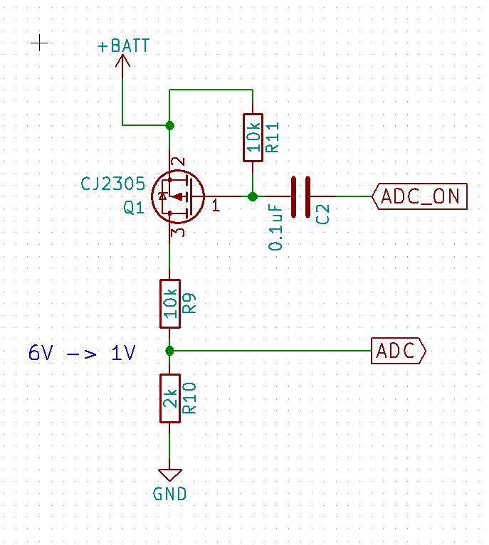
With some google magic I found that others had used a transistor to turn on and off the voltage divider.

    The reason that the transistor is on the high side of the divider is because otherwise the ADC input will be exposed to the battery voltage when the transistor is "open"(high impedance).

    Using a high side transistor(PMOS) introduce another problem. To be able to put it in "open" state, the gate(1) - source(2) voltage needs to be <=0V. A 3.3V µcontroller can't put out say 4.2V like in a fully charged LiPo battery. One way could be to but transistor in between to step up the voltage, but I found one way that works really good in this case and it is cheaper by using a capacitor instead as the step-up stage.

    It works in the way that the capacitor is conducting the AC part of the signal on ADC_ON. So falling and rising edge on a pulse will "jump over" the capacitor and "open/close" the transistor. According to some forum post a falling edge will "close" the transistor for 2 ms, enough time to make one sample of the voltage on the ADC pin.

    Here is some example code I have used with success:

      digitalWrite(15, LOW); //Close transistor
      int sensorValue = analogRead(A0); //Measure
      digitalWrite(15, HIGH); //Open transistor
      // Convert the analog reading (which goes from 0 - 1023) to a voltage (0 - 5V):
      float voltage = sensorValue * (6.85 / 1023.0);

    ADC_ON is connected to pin 15 on the ESP.

    I tried with delay(1) between LOW and READ but that was to long. This code have worked without problems.

    The 6.85 value is the value that corresponds to the battery value when the ESP measures 1V, but this was tested on one of my units and your miles my vary.

    Tip: connect to a good power supply and check what this code read and the calibrate the 6.85 value to something that works good for you. 

  • PCBA

    Johan Westlund01/01/2018 at 22:11 1 comment

    Long time, no update... But I have slowly made some progress. I finished the design before the summer but then let it rest for a bit. Then after the summer I started to look into ordering PCBs and components. QFN and 0402 are not funny to solder by hand.

    So I looked more and more into PCBA services.

    Found some different companies, but most of them required a lot of work or money to produce my boards. Then I found https://www.elecrow.com/cooperated-designers/ and sent them the gerber and BOM files. They where very helpful in the process of deciding amounts, finding components and other stuffs. After some emails and payment they produced 50 units. 25 for me and 25 for their online shop so everyone here can buy one if they want: https://www.elecrow.com/homefixer-esp8266-devboard.html.

    Now I got 25 to test together with a friend and will update more when there is smoke ;) and testing.

  • V2 design

    Johan Westlund06/11/2017 at 15:59 0 comments

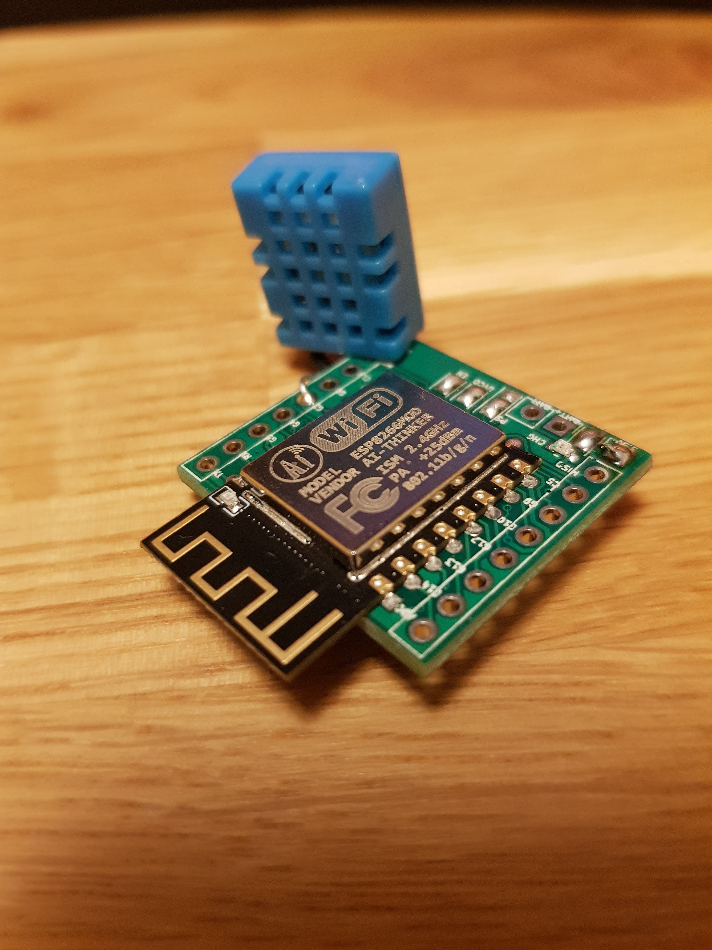
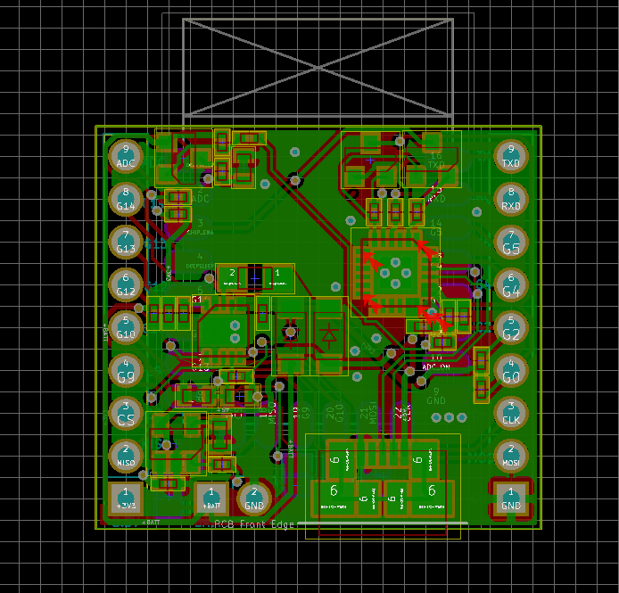
    Now V2 is almost done, some small DRC errors to fix before I can order it.

    Functions in V2:

      • Charger can be disable if using non LiPo batteries.
      • Powersupply has two diodes to prevent battery from being connected to USB/CP2104 and USB from directly connecting to battery.
      • CP2104 is supplied from USB so it should not draw power from battery
      • Auto Reset when programming in same way as nodeMCU
      • ADC to battery with ~2 ms on time of the voltage divider to save power

    • V2 ideas and comparison

      Johan Westlund05/19/2017 at 10:13 0 comments

      ADC for battery voltage reading:

      Requirements: 6V -> 1V, don't destroy the input, low power

      1. Fixed divider
      2. N-FET
      3. P-FET with capacitor control
      4. P-FET with N-FET control

      1 is out because it requires continues current and really big values on resistors.

      2 might put 6V on the ADC input when off, we don't want that.

      I thought of 4 until I found 3. 3 will be cheaper and smaller to implement and I hope it will work so I'm going for that at the moment. Values of resistor will be decided later to keep number of rows in BOM as small as possible.

      Some ref:

      http://fettricks.blogspot.se/2014/01/reducing-voltage-divider-load-to-extend.html


      USB2Serial:

      Requirements: Able to restart to programming mode

      Candidates found:

      1. CH340
      2. CP2102
      3. CP2104

      I settled for the cp21* family as it has better driver support and the part 3. CP2104 as it was used in other projects so I knew it worked.

      Some ref:

      https://www.adafruit.com/product/2821

      http://imgur.com/tW6tGr2

      http://community.silabs.com/t5/Interface-Knowledge-Base/Differences-between-CP2102-and-CP2104/ta-p/158933 but I have seen smaller CP2102.

      On autorestart:

      http://hallard.me/esp8266-autoreset/

      https://github.com/nodemcu/nodemcu-devkit-v1.0

      https://github.com/esp8266/Arduino/issues/480https://github.com/esp8266/Arduino/issues/480

      Disable when running from battery:

      https://tinker.yeoman.com.au/2016/05/29/running-nodemcu-on-a-battery-esp8266-low-power-consumption-revisited/


      Charger:

      Requirements: Lipo

      Only found MCP73831T so far.

      Some ref:

      https://www.sparkfun.com/products/11231

      https://www.adafruit.com/product/1944


      Regulator:

      Requirements: 1 AA to 4AA, Lipo, NiMH etc. (0.8V to 5.5V)

      TPS61200 is the candidate but looking for cheaper ones.

      Some ref:

      http://www.ti.com/lsds/ti/power-management/boost-converter-integrated-switch-products.page#p634min=1;3.3&p634max=5;10&p834typ=0.5;3&p32=1&p236typ=0.0003;0.4&p1130=0.17;3


      First Draft schematic:

      Added diode to prevent battery from powering CP2104

    • First try

      Johan Westlund05/16/2017 at 19:15 2 comments

      As got all components one week ago, I started to solder 5 boards. Result: 2 out of 5 works.

      First problem was the tools I had available and the size of the components. To solve it I put on a lot of solder and then removed it again just to get flux on the pads. It really helped in sucking the solder to the pads and component the next time.

      I believe that there is some shorts under the QFN on the bad ones. Will look more into it later, but for now the priority is to make 2.0 with fixes and features I really miss in 1.0.

      One of the boards was put into use as a wifi thermometer sending data to thingspeak every 10 minutes. It have been running for a week with only missing half a day because the ADSL modem went down. The box haven't been touched after it was closed.

      Some more problems discovered:

      ESP8266 only reads 0-1V on the ADC, will have to edit the current design.

      PCB was .1" to big for my breadboard, have to squeeze it a bit for the next one.

      The current placement of the temp. sensor makes it a sun detector. xD

    • PCB order

      Johan Westlund03/29/2017 at 12:18 0 comments

      TIP: If using seeedstudio that have 100x100mm boards *10 for 9.9 USD. If your board is rectangular and smaller then 100x100mm, PANELIZE it :) I put 9 copies on the 100x100mm board and in that way got 90 boards now :D see the background picture for the result.

    View all 8 project logs

    • 1
      V2

      Need to be soldered for 3.3V regulator to work

      Green: Disable powersave feature on TPS61201.

      Yellow: Enable powersave feature.

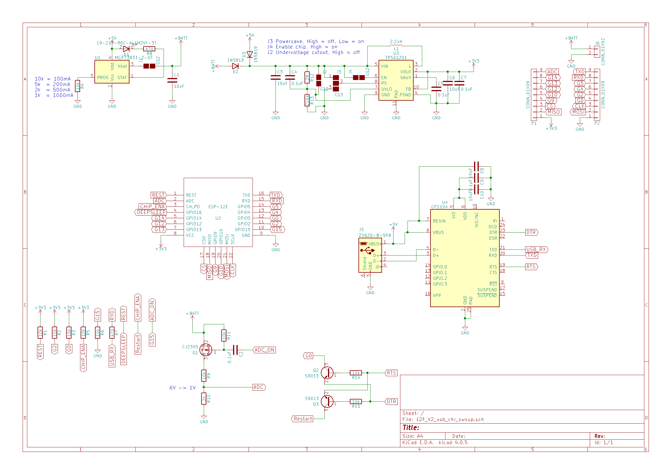
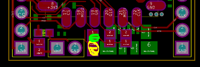
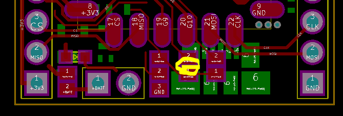
      De solder to enable under voltage shutdown. (Good for shutdown on low battery to prevent deep discharging of lithium batteries)

      Solder to enable 3.3V regulator. (can be used to connect to something for switching on and off)

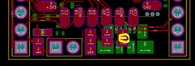
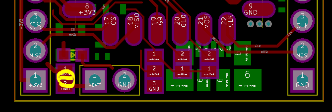
      Solder to enable lithium charging.
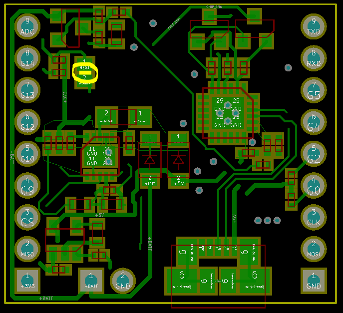
      Solder to enable deep sleep.

    View all instructions

    Enjoy this project?

    Share

    Discussions

    Similar Projects

    Does this project spark your interest?

    Become a member to follow this project and never miss any updates