Close
0%
0%

Raspberry Pi-based SmartZoom Imaging

Using a laser rangefinder, distance from camera is calculated and display of image is zoomed in or out dependantly

Similar projects worth following
This project is based on my homebrew laser rangefinder project that uses the distance between laser dots to calculate the distance between the unit and the target. The camera used to create the images to be analyzed will also have a direct feed to a small (5-7 inch) LCD that will display a zoomed in image correllated directly to the distance from target. This can be used for precision rangefinding and tracking a target in multiple use scenarios.

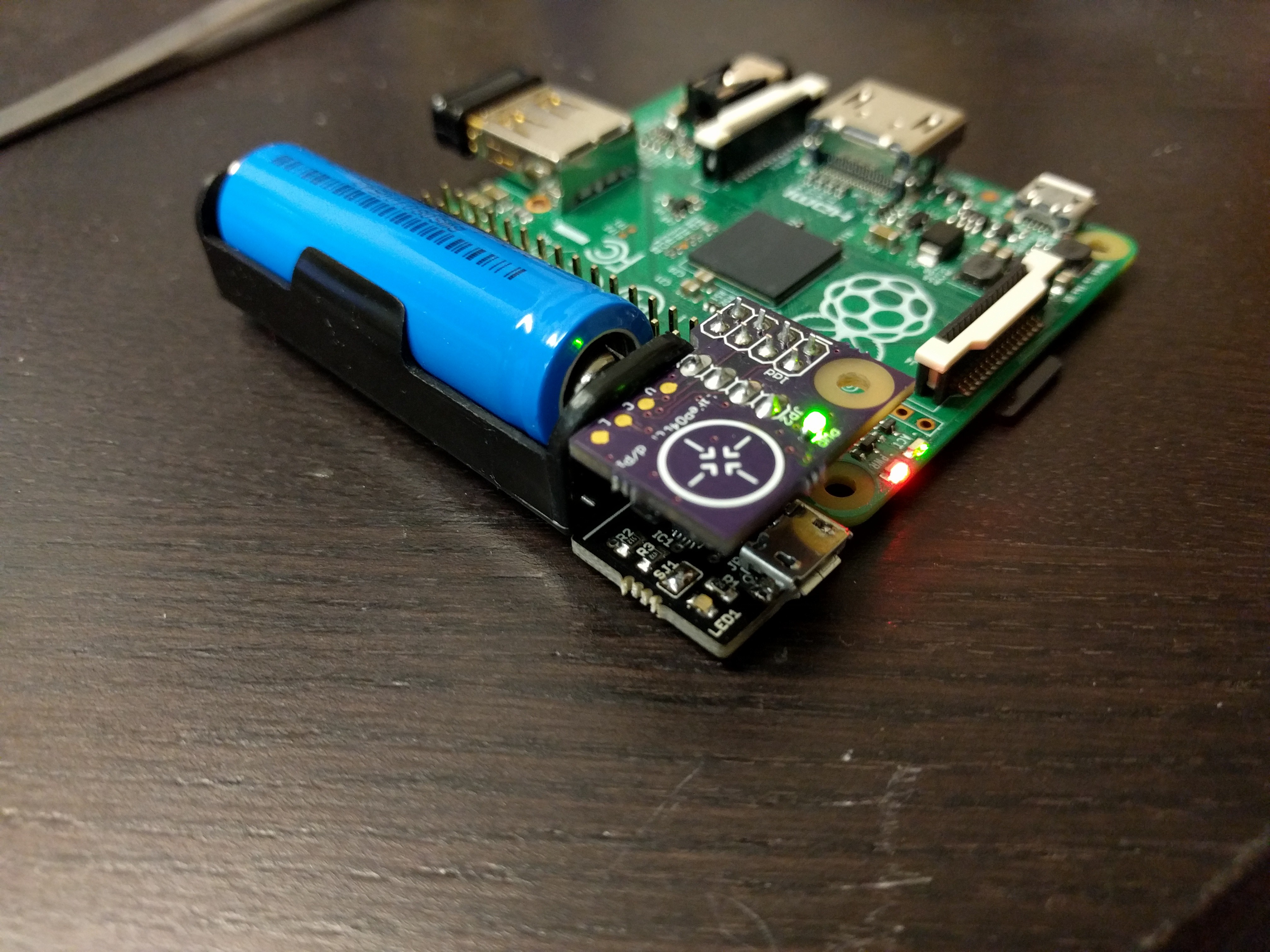
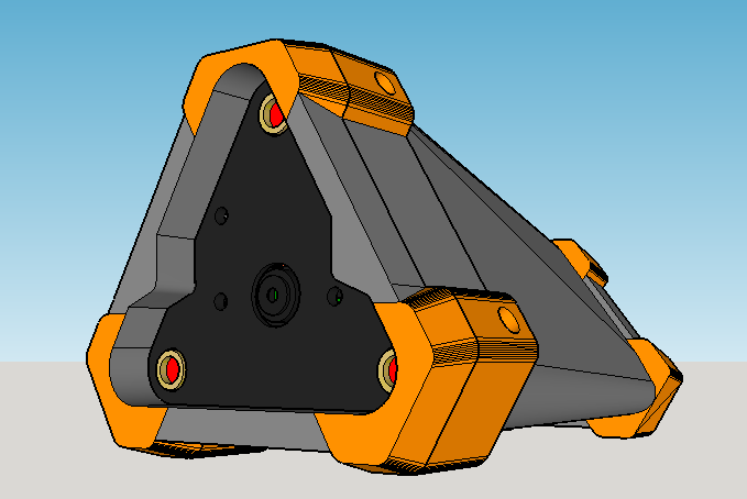
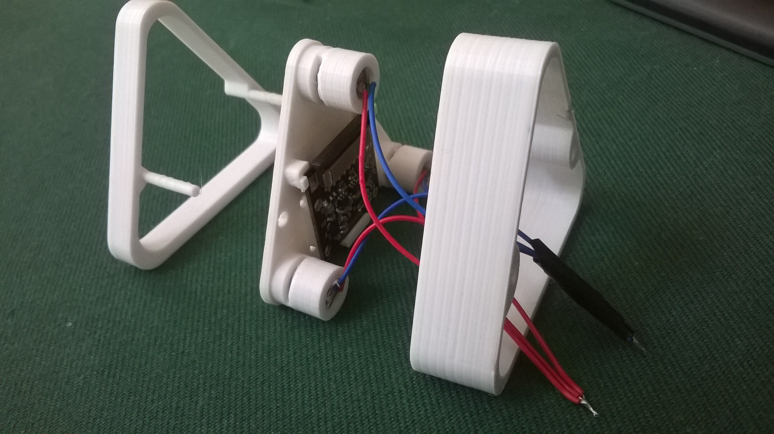
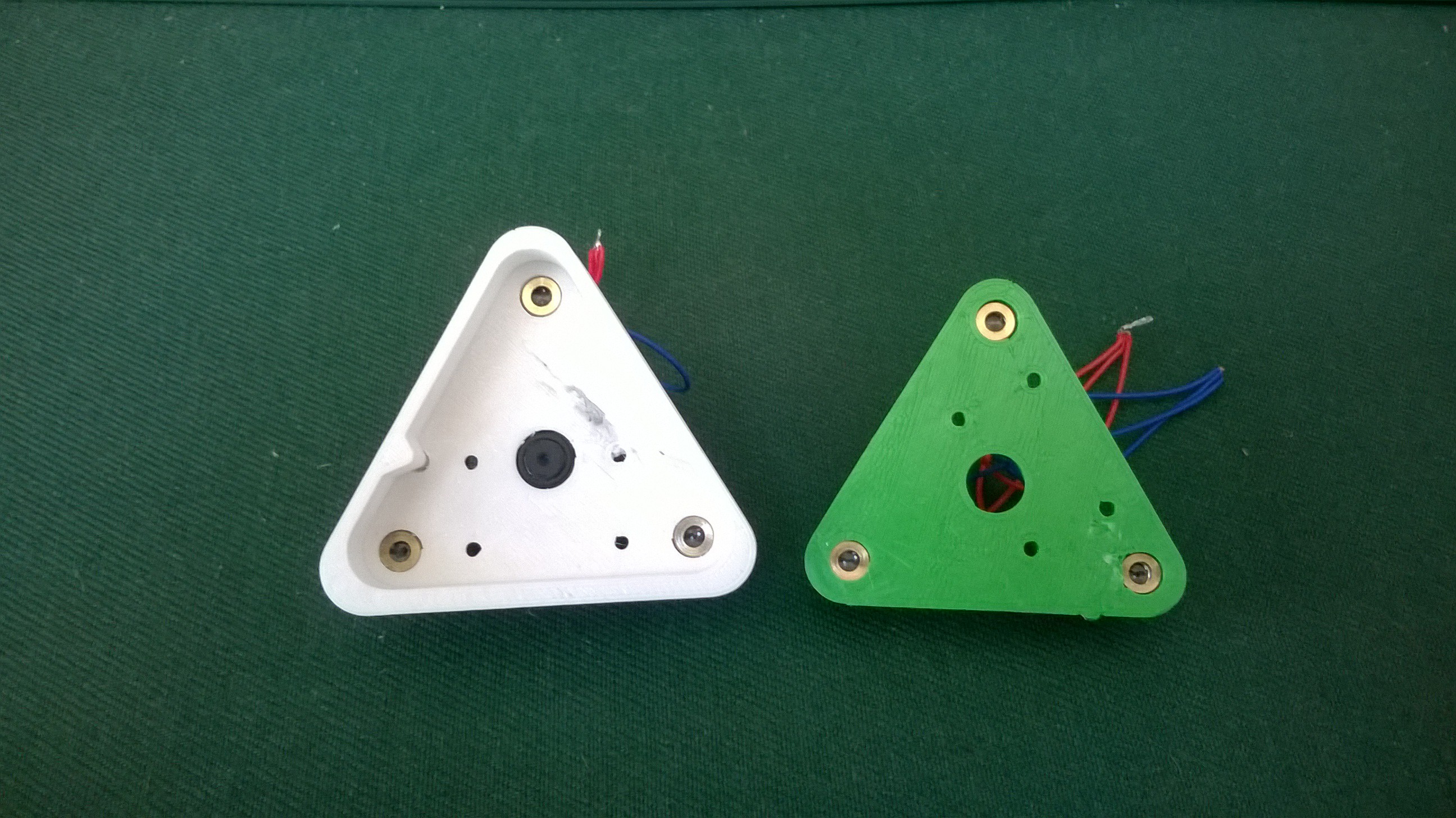
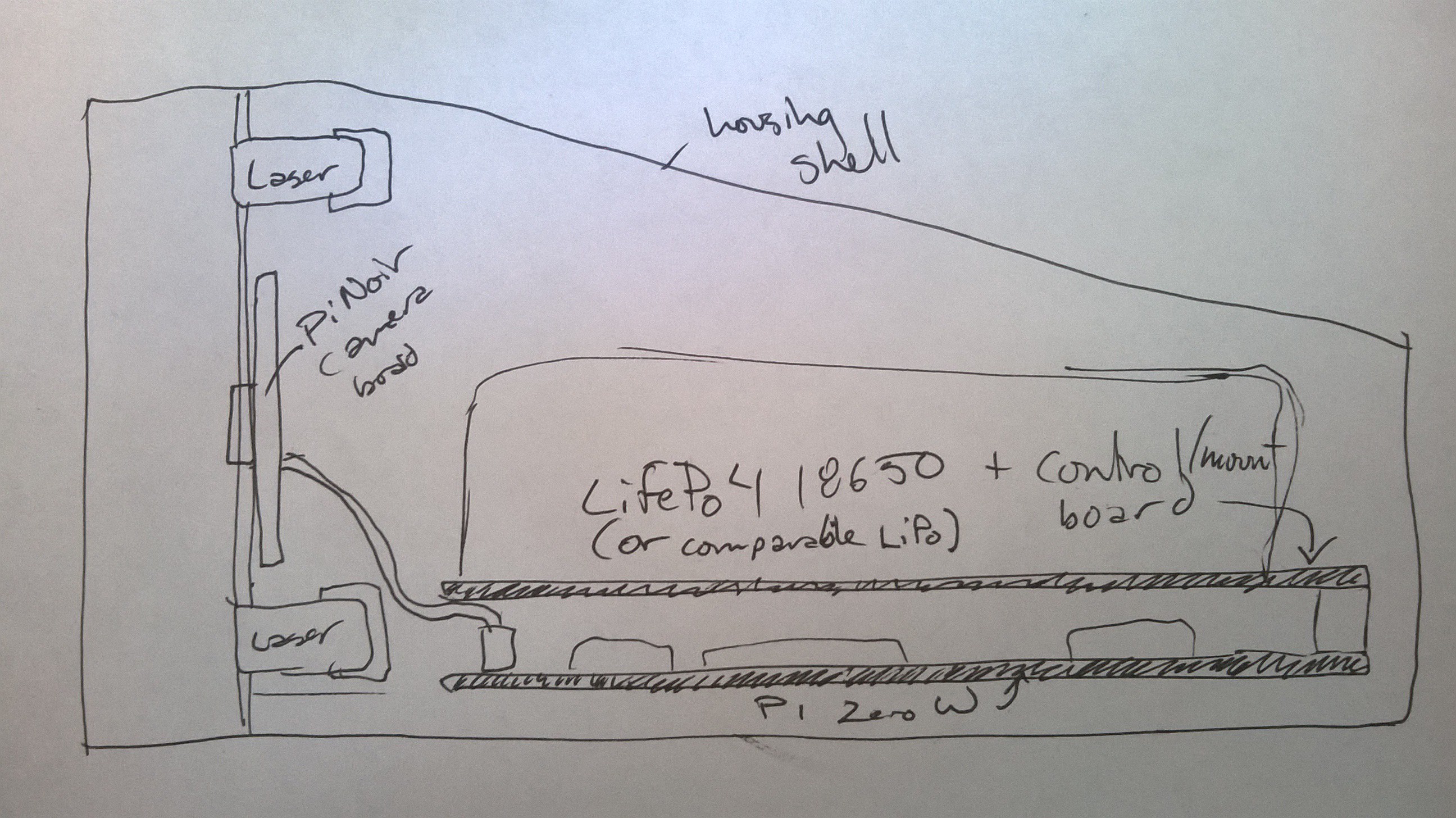
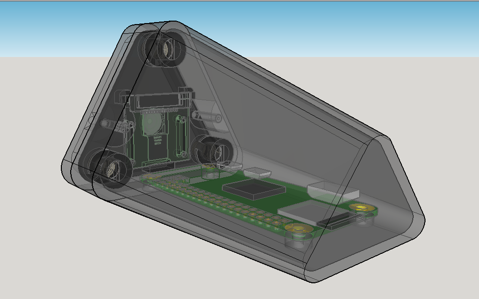
The idea behind this project is you have have three lasers pointed in the same direction. If at least two of the laser dots fall on an object, the distance between the dots is measured in pixels. This measurement is used to create a 'distance to object' value.

If this 'distance to object' value is below a threshold (set by software and adjustable by a manual potentiometer) then the image is zoomed in or out by means of resampling a specific area of the image, or gathering another wider view image until the value falls within the threshold range.

This project can be applied as a higher precision rangefinder, ensuring that the target is continuously tracked and if the target goes behind another nearer object, a larger field of view is available for target re-aquisition)

There are lots of image analysis and display options out there. Some of the options I have been considering include using a Raspberry Pi 3 connected to Zero via WiFi + a 5" LCD, or using a small Android tablet/smartphone with the Pi Zero W as an Android 'Thing'.

  • 3 × Cheapy laser diodes 5V powered
  • 1 × Raspberry Pi Zero W Not yet in my collection, but I will do testing on Pi 3
  • 1 × Pi Noir camera module What I have, or one with a similar form factor
  • 1 × 3D printed housing designed specifically around components I have
  • 1 × 18650 LiFePo battery and boost kit https://hackaday.io/project/9461-lifepo4weredpi from 3.7V up to 5V

  • Power source

    ken.do09/03/2017 at 03:02 0 comments

    I got a LiFePo4wered Pi power source from Patrick some time ago.

    This is a great little power unit. A 18650 joins up with the GPIO pins and hangs off the side of the Pi. For my application, I will need the LiFePo above a Pi Zero. A few minor alterations should put things where I need them.

  • Case mod

    ken.do04/16/2017 at 00:13 0 comments

    I modified the design of the case to accomodate #6 screws and nuts for the adjustment of laser aim. It also looks cooler.

  • How to find the distance between dots

    ken.do04/10/2017 at 14:02 0 comments

    Using this guide I should be able to find one brightest spot. Extrapolating this code to include the second brightest or equally bright spot shouldn't be too hard.... :P

    Laser precision does not have to be perfect. As long as the beams are shooting in the same direction and do not intersect, and they remain equally distant from each other, it should be fine.

    Alignment will be adjusted by external thumbscrews. I haven't worked these into the housing yet but will come soon.

    Calibration will be done measuring the distance between dots at set intervals, or by using a template and recording the distance from the finder when the dots match up with the template of concentric triangles. The key is that the dots are roughly equidistant to each other.

  • Pi Zero W-based laser rangefinder

    ken.do04/03/2017 at 21:19 1 comment

    I printed out my preliminary design for the front part of the rangefinder housing and fitted some of the electronics. There were issues.

    That is a Pi Noir camera board and three super cheap 5V red dot laser diodes

    They looked okay, but when the lasers came on, it was a different story. I designed it so that the diodes fit tightly. I figured, 'If the receptacle in the 3D model is straight, the lasers should shoot straight, right?' Nope. They were all over the place, probably due to manufacturing (in)tolerances. So I need to redesign with a way for the lasers to be aimed.

    Here is a rough idea of how the rest of the housing works...

    This housing can be mounted on a pan/tilt mount powered by the battery contained within, making the whole unit stand-alone.

View all 4 project logs

Enjoy this project?

Share

Discussions

justin.m.riddle wrote 05/24/2017 at 22:26 point

What would it cost to add a small OLCD screen, and perhaps a very very small numerical readout to the back for target acquisition and ranging?  I'd just need the internals, and probably another battery added so I can streamline it and make it easy to strap to my rifle or spotting scope.

What do you think the max range on this is?  I'm still reading up, so if you've mentioned it, I haven't gotten there yet.  You make something like this that can hit 500, 750, or 1000 yards and there's huge potential.  Heck, I'd be happy with 300 for version 1.

  Are you sure? yes | no

David Knochenhauer wrote 05/24/2017 at 12:41 point

Link to "guide" is down

  Are you sure? yes | no

ken.do wrote 05/24/2017 at 16:11 point

Fixed. Thanks!

  Are you sure? yes | no

ken.do wrote 04/10/2017 at 13:59 point

Laser precision does not have to be perfect. Alignment will be adjusted by external thumbscrews. Calibration will be done measuring the distance between dots at set distances from the unit. The key is that the dots are roughly equidistant to each other.

  Are you sure? yes | no

Legrange wrote 04/10/2017 at 08:33 point

This sounds interesting. How precise should the lasers be aligned for it to work as desired and what kind of calibrtion procedures would be necessary?

  Are you sure? yes | no

Similar Projects

Does this project spark your interest?

Become a member to follow this project and never miss any updates