 Yann Guidon / YGDES
This educational project covers the whole HW/SW gamut :
- it draws a lot from my Raspberry Pi educational boards,
- it's a scaled-down and updated version of #SPI Flasher
- it uses the #HTTaP protocol, implemented by the #micro HTTP server in C.
- it uses the #C GPIO library for Raspberry Pi for low-level access
"Simon Says" is a natural application because it's simple (much simpler than Tetris for example) but not trivial, and lets the students learn many inter-related subjects while having fun. This solves one issue I found : my workshop focused on either inputs or outputs, but not both.
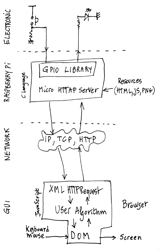
As you can see in the abstracted doodle below, the "full stack" aspect ranges from the electrons and photons of the LEDs all the way up (down?) to the dynamic, abstracted, virtualised JavaScript program running on your browser.
The project covers:
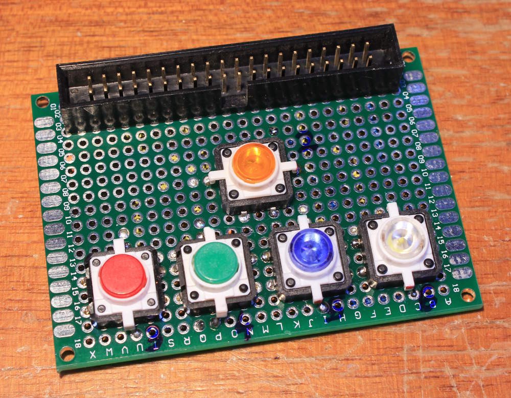
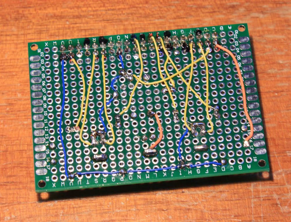
- The hardware part : setup a Raspberry Pi, make it work and learn about the GPIO. Then move on to building a board with 5 buttons/LEDs, as well as a few other status LEDs and a buzzer.
- The software part : the Operating System must be flashed to the memory cart, one must apply basic setup/maintainance then the real fun actually starts ! The high-level logic must be written in a HTML/JavaScript page while the low-level features must be written in C.
That's a lot to discuss, and I hope I'll have enough time in May 2017. Hopefully the whole system will be operational and ready to teach in september.
As you can imagine, implementing the game engine itself is may account for only 2% of the total time spent on the project... The real fun comes from developing the other lower layers !
Logs:
1. First prototype
Credits for the doodly logo go to @Blecky


 DeckerEgo
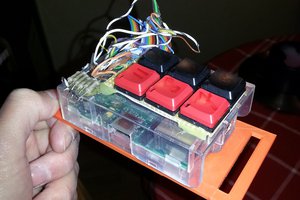
 Daemon informatica
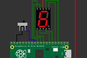
 Open Technology
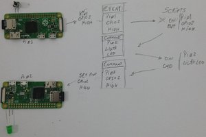
 Diogo Souza da Silva
I got the same buttons recently. In my case, the green seems a lot dimmer that the other colors. Is it the same for you?