 Yann Guidon / YGDES
Time to actually build it !
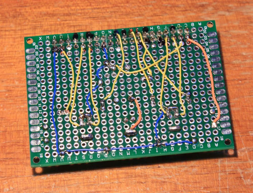
For a first board, I put 100Ω in series with each LED and 39K for the pulldowns.
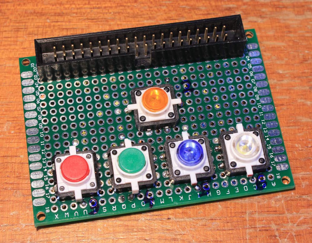
| LED GPIO | color | Switch GPIO |
| 22 | Orange | 2 |
| 23 | Red | 3 |
| 24 | Green | 4 |
| 25 | Blue | 5 |
| 26 | White | 6 |
The PCB is too small to make the typical cross but the 5 switches fit anyway.
Now, let's code !
for o in 22 23 24 25 26
do
  echo $o > /sys/class/gpio/export 2>&1 > /dev/null
  echo out > /sys/class/gpio/gpio$o/direction
done

while true
do
  for o in 22 23 24 25 26
  do
    echo -n " "$o
    echo 1 > /sys/class/gpio/gpio$o/value
    sleep .3
  done

  for o in 22 23 24 25 26
  do
    echo -n " "$o
    echo 0 > /sys/class/gpio/gpio$o/value
    sleep .3
  done
done
The green LED is quite dim, as noted in a comment of the project's main page.
...
Aaaand... the buttons don't work ! I totally forgot about the internal pull-ups...
In particular, GPIO2 & 3 are wired for I²C and have a 1K8 pull-up, the 39K pull-down lowers the voltage to 3.15V. Others are measured at 1.6V, meaning that about 30K of pull-up is already present. Damnit !
So there is no need of pull-downs and the common rail can be tied to GND instead of Vcc.
for o in 2 3 4 5 6 22 23 24 25 26 ; do
  echo $o > /sys/class/gpio/export
  sleep 0.1
done
sleep 1
for o in 2 3 4 5 6 ; do
  echo in > /sys/class/gpio/gpio$o/direction
  sleep 0.1
done
for o in 22 23 24 25 26; do
  echo out > /sys/class/gpio/gpio$o/direction
  sleep 0.1
done
echo "loop:"
while true
do
  for o in 2 3 4 5 6
  do
    if [ "$(cat /sys/class/gpio/gpio$o/value)" = "0" ]
    then
      echo 1 > /sys/class/gpio/gpio2$o/value
    else
      echo 0 > /sys/class/gpio/gpio2$o/value
    fi
    sleep .01
  done
done
Now the buttons return 0 when pressed...
The init code has taken quite a while to finally work, some setup time seems to be required...
.
Discussions
Become a Hackaday.io Member
Create an account to leave a comment. Already have an account? Log In.
>The green LED is quite dim, as noted in a comment of the project's main page.
There are two types of green LED semiconductor junctions. One has a forward voltage of about 2V and the other about 3V+. The former is sometimes hard to distinguish from yellow. I used this type in my project https://hackaday.io/project/175396-6-segments-suffice The latter is sometimes described as deep green or emerald and has high efficiency. You can see that there is little headroom for the current limiting resistor if driving from 3.3V. Unfortunately I discovered early in the piece that RPi GPIO is 3.3V as opposed to the 5V of Arduino GPIO. So it's the latter I usually turn to when testing old-school 5V logic.
Are you sure? yes | no
i could add a current buffer if the luminosity was critical, as the 40-pins port has a +5V pin and 2 resistors and a BJT would be enough, but I have other priorities now :-)
Another solution would be to change the LED inside the button but it seems to be sealed.
Are you sure? yes | no