 Yann Guidon / YGDES
Some time ago, like, 10 years ago, Dieter Müller worked on http://6502.org/users/dieter/decl/decl1.htm for his next discrete computer and he had to shelf the idea. I have the pretention to do better :-P
Why ?
- Because I have a viable computer architecture (the YGREC, as described in #AMBAP: A Modest Bitslice Architecture Proposal and #YGREC-РЭС15-bis, and now the smaller #YGREC8) so the ISA and structure are well understood and out of the way. As long as I got MUX, I can build it.
- I also have new laboratory equipment that would help. It's good to be able to inject 4× 200MHz signals and watch them on a 500MHz scope :-)
- Because I have Dieter's log to examine and take lessons from !
- And my new secret weapon : the BFS480... two 7GHz GBW transistors in a single, tiny SOT323-6 package (aka SC70), a 10× increase in density (I'm not even taking double-sided PCB into account because I don't feel like doing 4-layers PCB, we'll see if I'll be compelled)
Of course it will be hard but I have already solved many issues with the relay implementation. Dieter's log correctly warns about signal distribution across the whole processor, but I counter with this:
- smaller transistors means smaller circuits and shorter traces. The SC70 package is very low profile so the bitplanes can be stacked much closer to each other, 5mm apart instead of 25mm apart with the relays. This greatly shrinks the backplane ! That's less than 10cm for the distribution backbone, or roughly 300ps.
- I have thoroughly analysed the fanout, partition and distribution of the main control signals of the YGREC so they are under control. Instead of spending my time playing with a few ECL gates to make them run faster, I'll focus on the distribution networks, where all the speed is actually lost. I can cut corners with the logic gates, sacrificing a bit of raw speed for a low power consumption and fewer transistors (which again, just like in ASIC design, is a virtuous circle)
I just hope that I'll have enough parts...
Logs:
1. A sidequest, already
2. moving forward
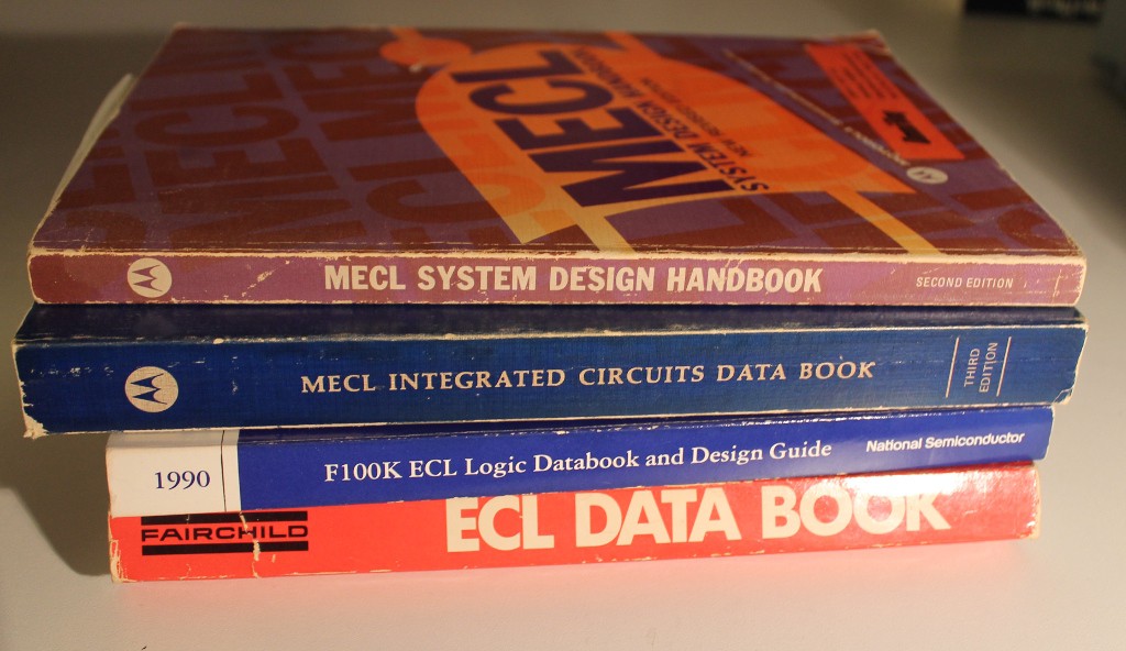
3. Bibliography
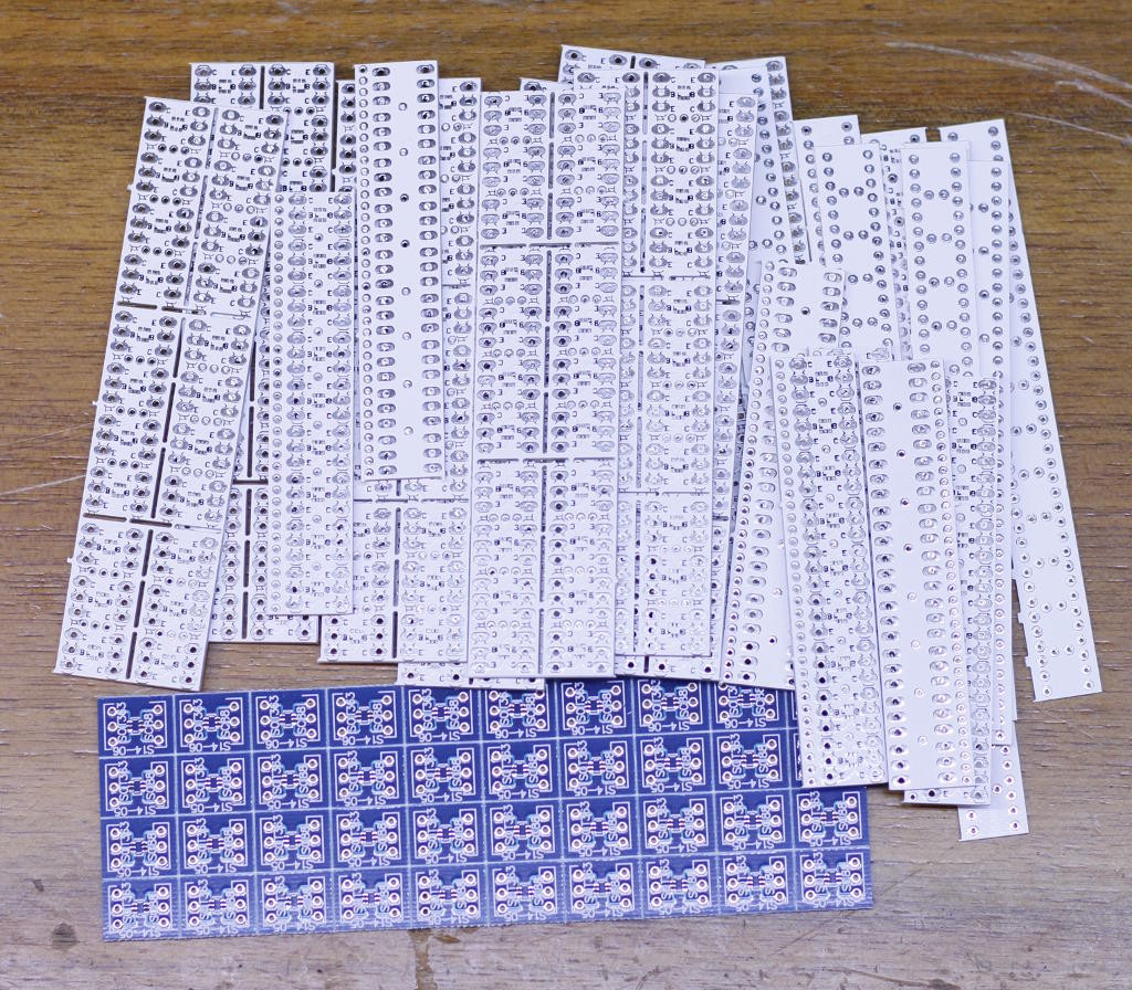
4. Protoboards
5. Even faster !
.


 CapitanVeshdoki
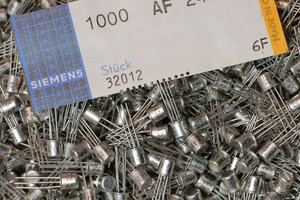
 jbb
jbb
well I'll have to compare LVI with ECL...
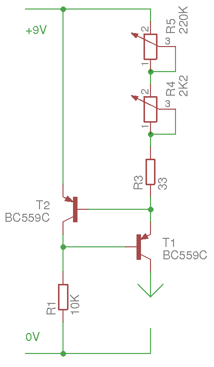
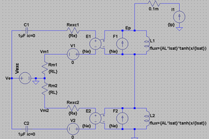
Attempting to design custom LVI inverters