Close
0%
0%

LiFePO4wered/Pi+

Next Gen LiFePO4 battery / UPS / power manager for Raspberry Pi, ideal for headless and IoT use

Public Chat
Similar projects worth following
Many IoT and other projects are based on the Raspberry Pi, but usually little thought is given to the power supply. Most project use generic cell phone adapters or USB power banks, which is fine for one-off projects where the duct taped parts and cabling don't matter and it's expected that SD cards will die because power was removed with the Pi running.

But when you need reliable non-stop operation for your prototypes, or you're ready to turn your project into a good looking product, or you want to use different power sources such as solar, it's time to look for a serious power manager for your Pi.

Built on the solid foundation of the #LiFePO4wered/Pi, this project provides Pi bootup and shutdown management based on button or touch, input voltage, battery voltage and time, all while making sure the Pi always performs a clean shutdown before power is removed.
In addition it provides significantly higher power, RTC functionality and Pi current measurement.

It was a hard decision to start from scratch with a new project for this next gen effort since the #LiFePO4wered/Pi project has such good traction and a gazillion likes, but the more I thought about it, the more I realized that starting with a clean slate would allow me the freedom to make this what people want it to be instead of feeling shackled by legacy, and at the same time prevent confusion about the different generations. A new project also allows me to enter it for the 2017 Hackaday Prize. :)

There are some issues with the current #LiFePO4wered/Pi design that I hope to address in this Next Gen effort:

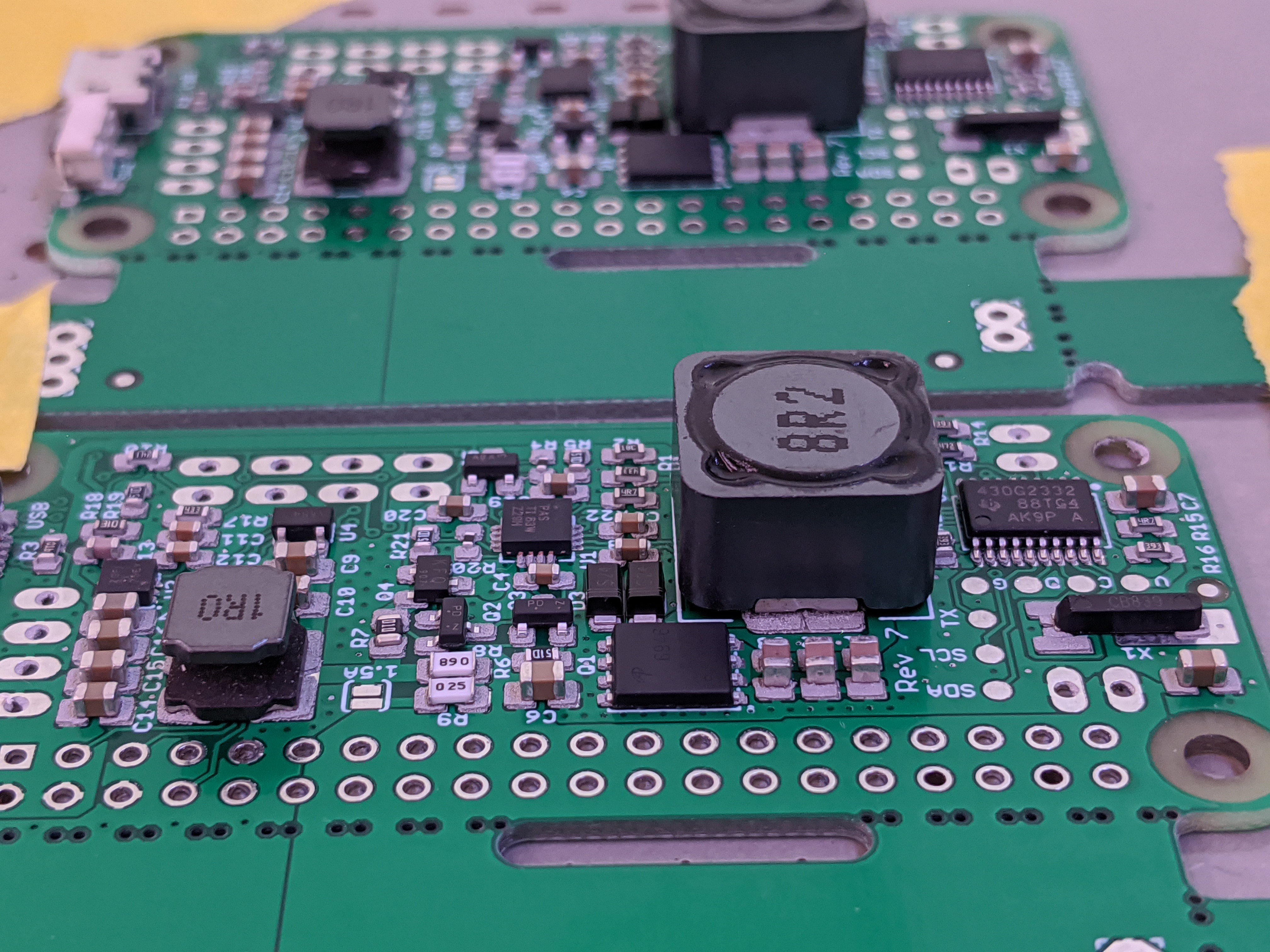
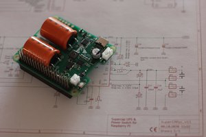
1. Make it easier to assemble. The two-PCB arrangement with the charger on the bottom and power manager on top makes for a nice and compact unit, but it takes too much time to assemble. The original design sprang from a desire to provide an example application for the #LiFePO4wered/USB, but the #LiFePO4wered/Pi has turned out to be a much more popular product in its own right. So this will be a single-board setup with the charger and power manager both on one PCB, significantly reducing assembly time and cost. It is the best way to reduce cost and support higher volume.

2. Alleviate power limitations due to physical size. Power supplies unfortunately generate quadratically more waste heat as the current goes up (P = I^2 * R), and the tiny PCBs in the current design have a hard time sinking this heat away. Customers always want more power, but recent experiments with higher power on the current physical design have convinced me that the only way to allow more power is a bigger PCB with more copper.

3. Improve hackability. For a product targeted at hardware hackers, the current design is not the most hacker friendly, mostly because there is very little room due to the small size. Customers want to connect different power sources, have the on/off button and LED remotely located, etc. The current design has some tiny surface mount pads to allow such things, but decent sized through-hole pads and more configuration and customization options would definitely be welcome.

4. Make load current independent of charge current. Some people don't need a big battery for long untethered run time, they just want a little bit of juice, enough to shut the system down safely when external power fails. But in the current design, maximum UPS load current is linked with charge current, which in turn dictates battery size. I hope to separate these two concerns and provide high load current with a small battery as well.

5. Improve physical stability. This isn't usually a problem, but the current mounting method with one screw and the weight of the battery supported on the 4-pin connector between the boards is not ideal. I plan to use a 40-pin header and connect to at least 2 screw holes.

So here is my current plan to make this happen:

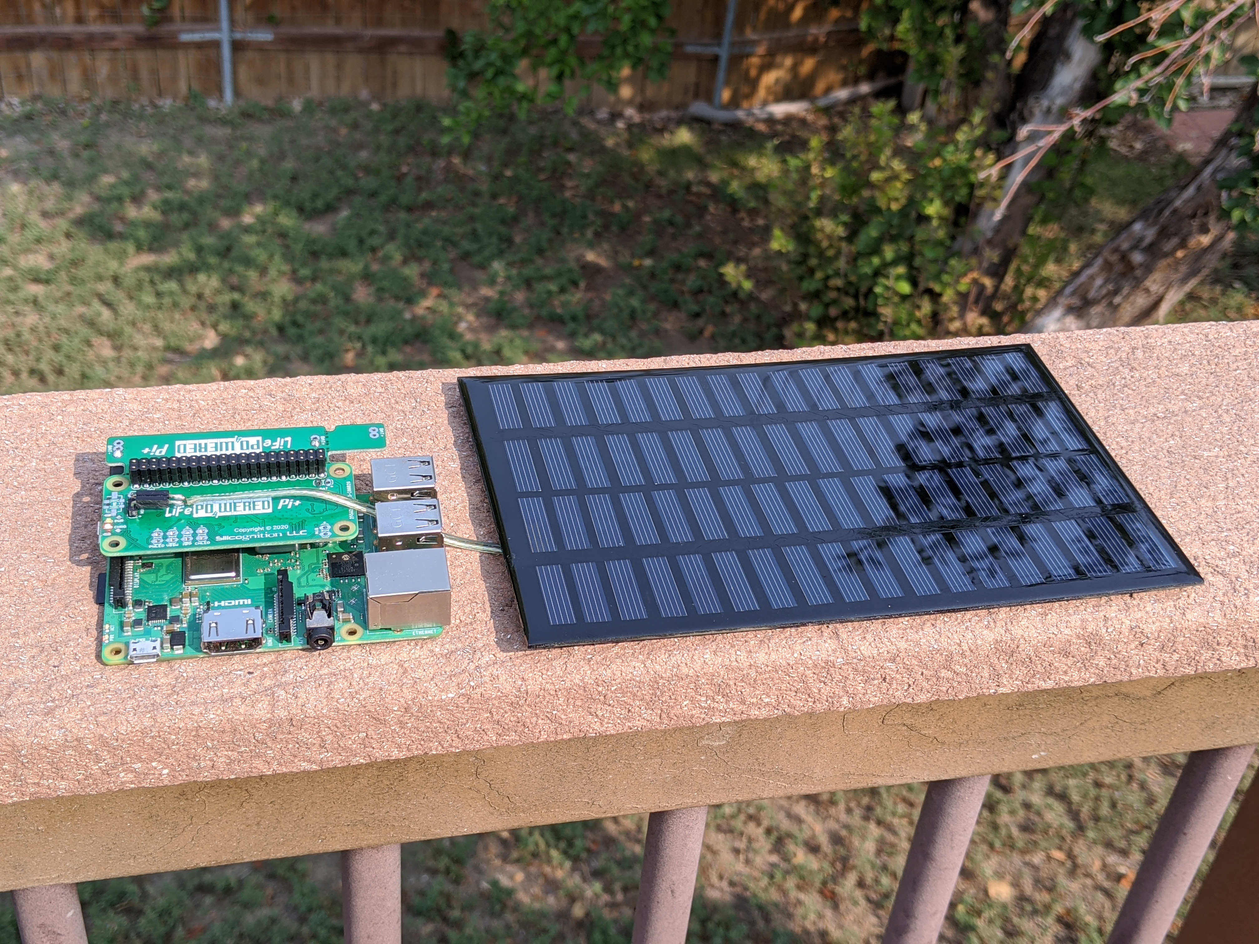
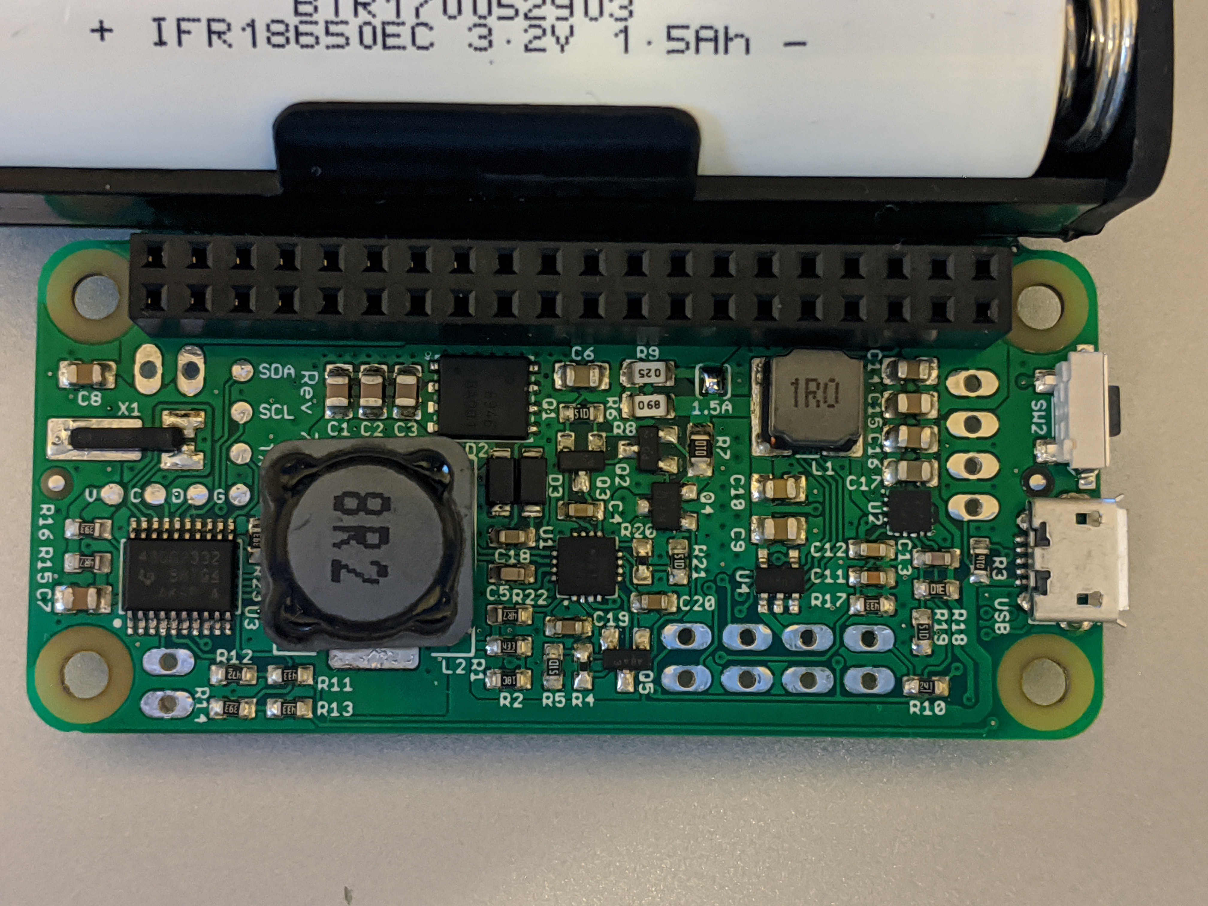
  • Start with a Pi Zero-sized PCB, extended past the GPIO header so the battery can still sit next to the Pi, but upside-down. Have one PCB design that can accommodate both the 14500 and 18650 cells. The 18650 will be located more forward than in the current design, making sure it doesn't stick out farther than the USB ports on a Model B+ any more.
  • The circuitry will be over the Raspberry Pi as is the case for most HATs. The components will be mounted on the bottom of the PCB, with only the on/off button (mechanical switch) and LEDs mounted on top. Most of the top of the PCB will be copper plane for heat sinking, on which an additional heat sink can be mounted if deemed necessary for high power applications.
  • There will be through holes for remote on/off button and LEDs, to easily connect input power other than USB, give access to 3.2V battery power and switched 5V output power, connect external LiFePO4 cells and loads, and adjust the charger's MPP for use with solar panels.

Anything I've missed? Comments and requests are not only welcome but highly encouraged!

LiFePO4wered-PiPlus-8.pdf

LiFePO4wered/Pi+ rev 8 schematic, CC-BY-SA licensed

Adobe Portable Document Format - 46.97 kB - 01/21/2024 at 19:29

Preview
Download

LiFePO4wered-PiPlus-7.pdf

LiFePO4wered/Pi+ rev 7 schematic, CC-BY-SA licensed

Adobe Portable Document Format - 46.04 kB - 01/21/2024 at 19:29

Preview
Download

LiFePO4wered-PiPlus-5.pdf

LiFePO4wered/Pi+ rev 5 schematic, CC-BY-SA licensed

Adobe Portable Document Format - 43.68 kB - 11/01/2019 at 21:28

Preview
Download

LiFePO4wered-Business-Pitch.pdf

Buniness Plan/Pitch for Hackaday Prize Best Product

Adobe Portable Document Format - 308.92 kB - 07/21/2017 at 19:20

Preview
Download

sheet - 10.73 kB - 07/18/2017 at 21:06

Download

View all 6 files

  • 1 × CN3801 Power Management ICs / Switching Regulators and Controllers
  • 1 × TPS61236P Boost converter with bidirectional load switch
  • 1 × MSP430G2332 Microprocessors, Microcontrollers, DSPs / ARM, RISC-Based Microcontrollers
  • 1 × SSM3J338R Discrete Semiconductors / Diode-Transistor Modules
  • 1 × BSZ120P03NS3 Discrete Semiconductors / Transistors, MOSFETs, FETs, IGBTs

View all 9 components

  • 2000 mAh battery option!

    Patrick Van Oosterwijck09/14/2021 at 22:02 0 comments

    It's well known that LiFePO4 cells have lower energy density than other lithium-ion chemistries that use cobalt.  So I'm always very skeptical when I see LiFePO4 18650 size cells advertised with supposed 2500 - 3500 mAh capacities.  Usually it's either a confusing ad from a seller who crams their ad title full of keywords and they are not actually selling a LiFePO4 but a cobalt-containing lithium-ion cell, or they are just plain lying about the capacity.

    But a while back I was contacted by a company called OSN power who claimed that they had new LiFePO4 18650 size cells with 2000 mAh of capacity, versus the normal 1500 mAh.  My interest was piqued because it seemed like a serious, reputable company, and the claim was not outrageous but within the realm of possibility considering technology is always improving.  So I ordered 200 cells for testing.

    To be honest, I didn't have much time to actively spend on testing, so I did it in a way that would not take up much of my time but could run in the background while I was busy doing other things.  I set up a logging script on a Raspberry Pi that would read and log the battery voltage.  I would fully charge a battery, then start the script and run from battery until the system shut down because the battery was empty.  I did this for a couple of my standard 1500 mAh cells to have a reference, and then for a bunch of the 2000 mAh cells to get an idea for how consistent they are.  I tried to be consistent about not leaving the ssh terminal connected, but to be honest, I didn't do too well and introduced some variability because of that.  Sorry, my brain power was mostly elsewhere. :)  Still, all I wanted was data that would give me an idea of how much more capacity these cells had compared to my standard ones.  Here is a chart with run times I collected:

    Well, what do you know: the new cells indeed run the Pi for quite a bit longer.  The two shorter traces are my standard 1500 mAh cells.  Sorry for the variability between them, I accidentally left the ssh terminal connected for a while for the red trace.  For the 2000 mAh cells, I had the procedure down a bit better so they don't show too much spread.  Assuming my reference cells are indeed 1500 mAh, the new cells do seem to have 2000 mAh capacity or better!

    I started offering these batteries as an option now in my Tindie store.  If you want the higher capacity battery, choose the "High-capacity 18650 size 2000 mAh battery" option in the "Battery size" dropdown.  Happy hacking!

  • More rev 7 testing with NVMe SSD

    Patrick Van Oosterwijck10/21/2020 at 18:06 0 comments

    To test a real world high load scenario, I set up a Pi 4 with large heat sink (to maintain maximum frequency) and configured it to run from a 500GB WD Black NVMe SSD using a USB to M.2 adapter.  I also stressed the system with the following command:

    stress -c 4 -i 2 -m 2 -d 2

    I used an extra stacking header to make the LiFePO4wered/Pi+ fit above the heat sink.  Here's the setup:
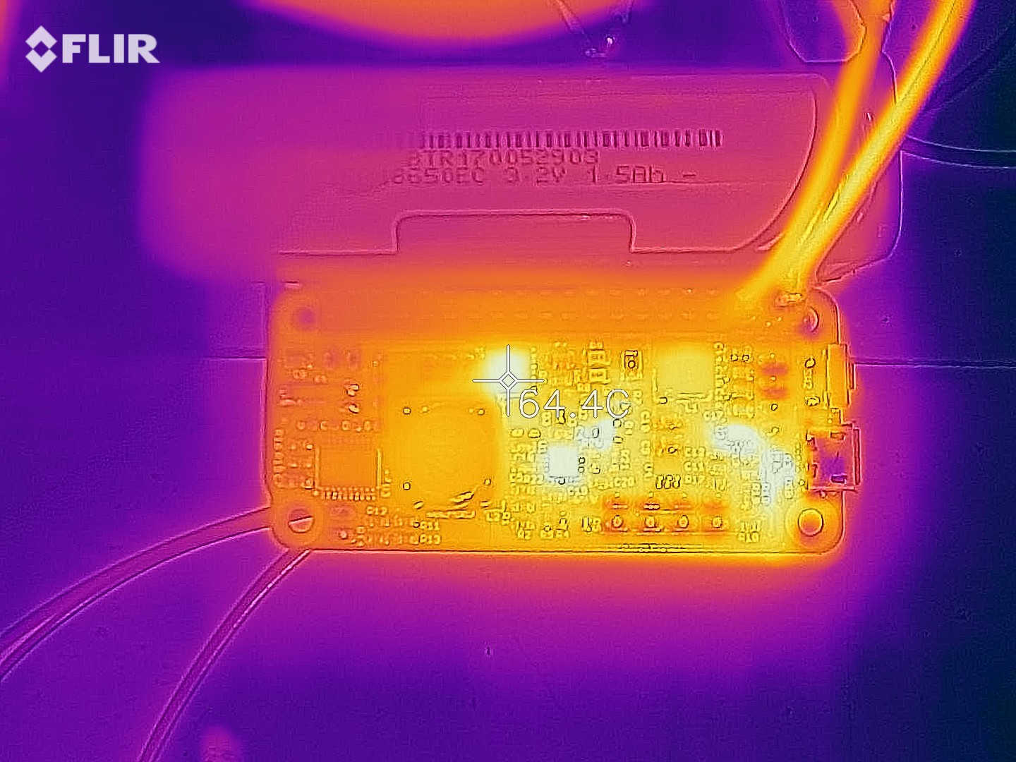
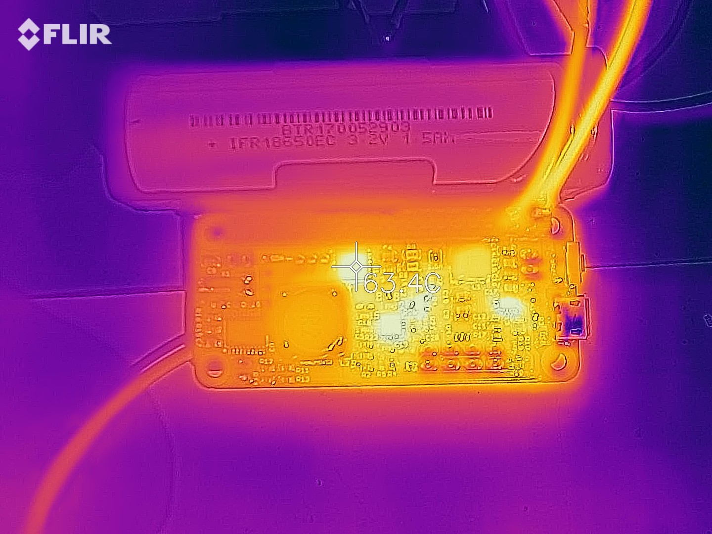
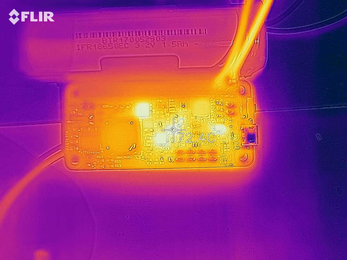
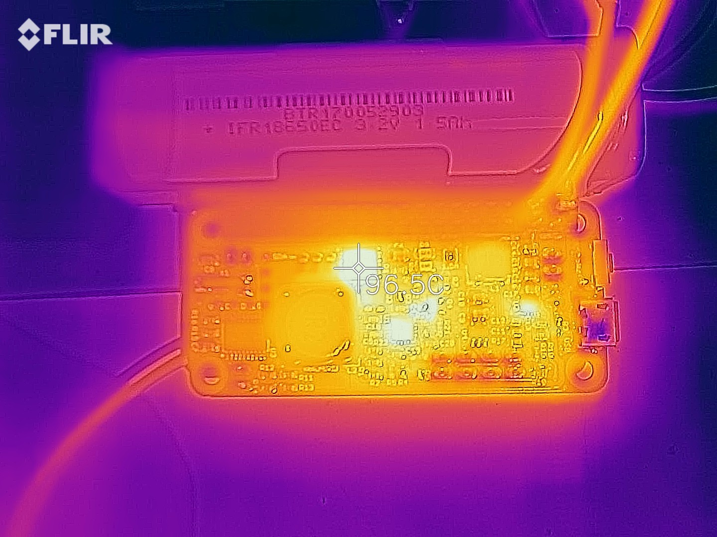
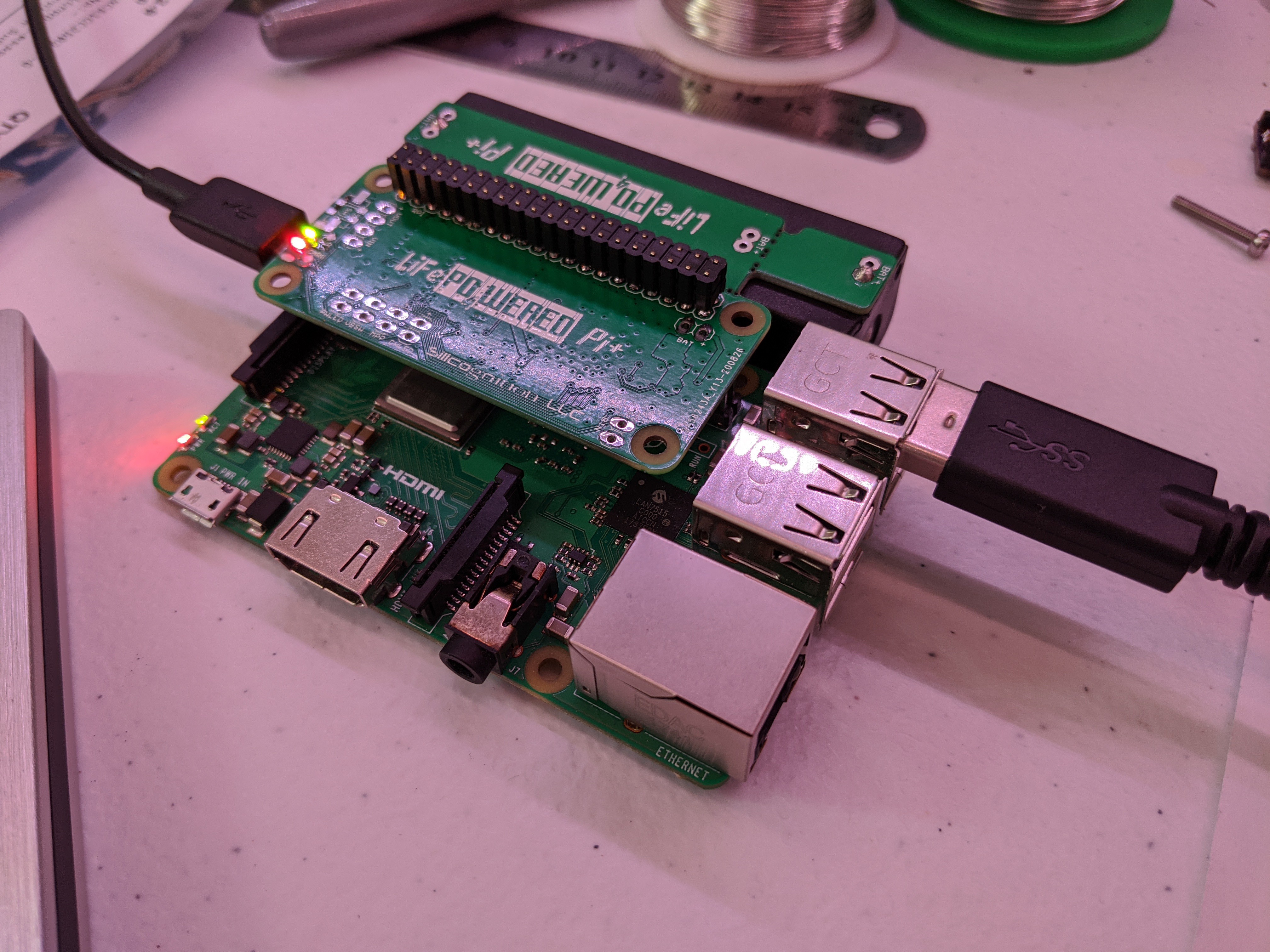
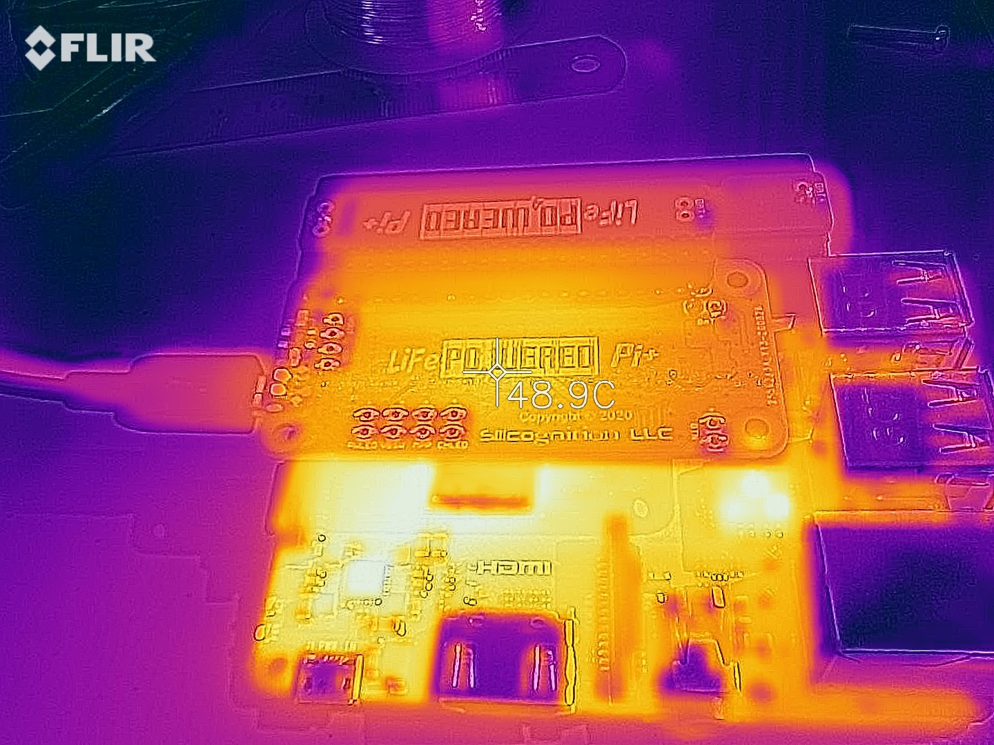
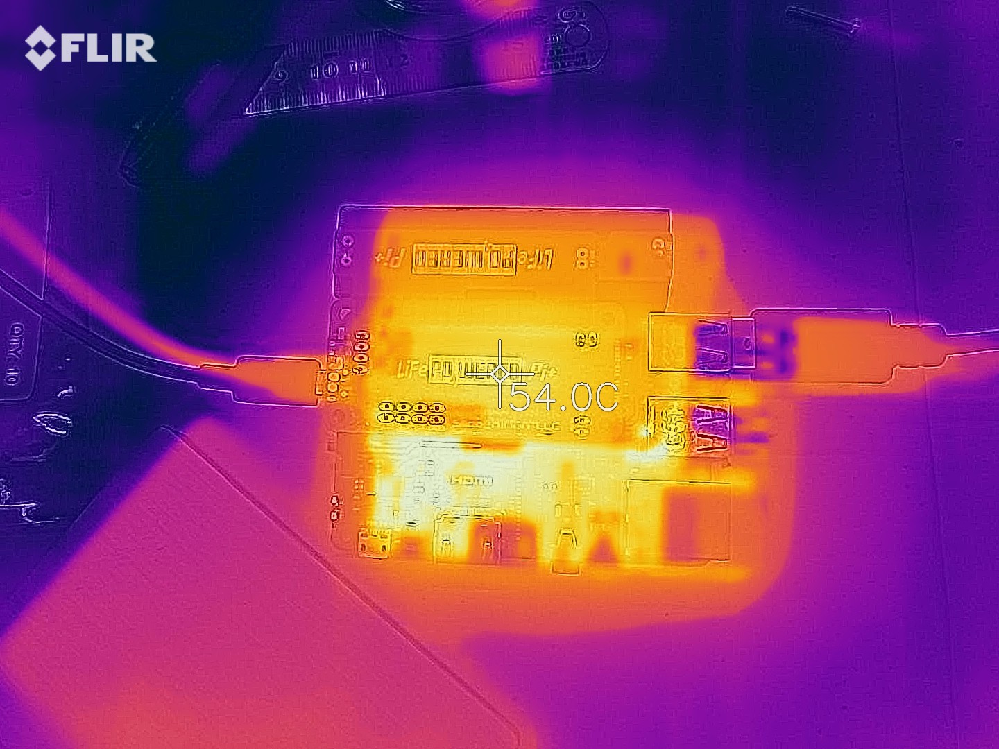
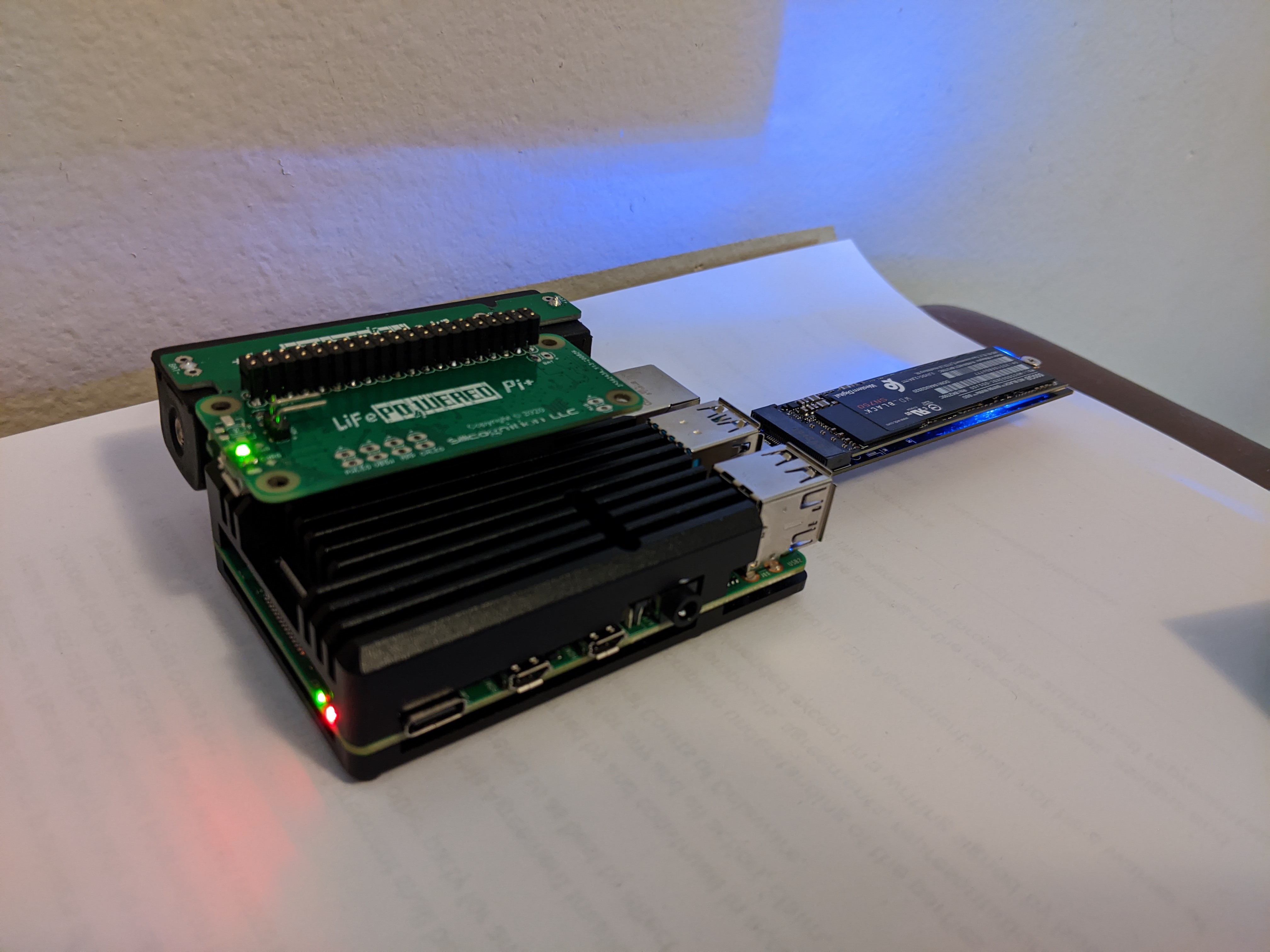
I wanted to make sure the system would run stable from both battery and when externally powered, and switch seamlessly between the two.  I also wanted to take some thermal shots in both conditions.
    Here's the first thermal shot when running from battery:

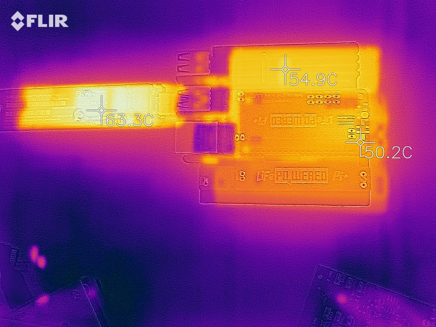
    Sorry about the bad alignment between the thermal and optical in this image.
    It shows that the temperatures at reasonable levels.  The SSD is the hottest, but keep in mind that that Pi benefits from a huge heat sink while the LiFePO4wered/Pi+ and SSD have to make do with whatever heat transfer to the air their parts and PCBs can manage.  If the Pi didn't have the heat sink, its CPU would be the hottest.  In fact, the command:
    /opt/vc/bin/vcgencmd measure_temp

    showed it at 73°C in this setup.  The load current would fluctuate between 1.6 A and 1.8 A.

    When the battery was getting low I plugged it in to external power and waited a while to let the temperature stabilize:

    I'm not entirely sure why the Pi's temperature would go up, it might just be that I hadn't let it settle for long enough in the first picture.  The SSD temperature is similar and the LiFePO4wered/Pi+'s temperature is higher because it now is also converting input power.  Still, all these temperatures are completely reasonable for a system under high load.

    I plugged and unplugged external power a whole bunch of times to ensure the UPS would do its job as expected and saw no issues.  Then I let the battery run out and observed that a clean shutdown was performed.  Everything working as expected!

  • More rev 7 testing

    Patrick Van Oosterwijck09/19/2020 at 00:10 1 comment

    I checked the solar charging capability with a 18 V nominal panel.  The MPP voltage for this panel is 15-16 V, so I added a 4.7 kΩ resistor to the MPP pads, which sets the MPP voltage to 14.6 V and put it outside.

    I measured that the solar voltage was being regulated to 14.7 V, close enough considering part tolerances.  Note that the panel in the picture was for testing only, this panel is too small to keep a Pi running.  It kept the charge up jut barely with a Model B+ in direct sunlight, a Pi 3B+ was too much.  For practical use, you need a bigger panel, or use a lower power Model A+ or Pi Zero.

    Next up, I tested heat generation under high load with high input voltage.  I applied 20 V on the input with 2 A load using my electronic load:

    The switching transistor, which was a hot spot in the old asynchronous design with high input voltage, is running at 64 °C, which is just fine.  Other hot spots are the charging chip (not entirely expected), the pass transistor and boost converter (expected), and... what's that hot spot near the USB connector?  Oh, the charge LED current limiting resistor.

    How much is that thing dissipating?  A quick calculation shows at 20 V input, this resistor dissipates about 0.36 W.  Oops, it's a 0.1 W resistor! :)  Gotta do something about that.  The 19 mA or so flowing through the LED may also be part of the reason the charge chip is getting hot, but most likely it's due to the built-in linear regulator that needs to drop 15 V at 20 V input.

    I changed the LED current limiting resistor from 1 kΩ to 4.7 kΩ, which should keep the current low and the dissipation in check at 20 V input.  On the other hand, at 5 V the current may become so low (less than 1 mA) that the LED is very dim.  Let's check that:

    Looks alright to me, the red CHRG and green PWR LEDs seem to be about the same brightness.

    Time to redo the high voltage input load test.  This time though, I also discharged the battery all the way, so the system has both charging to do and the load to supply.  Not sure if it made much difference, but hey, let's try to do it right:

    First thing of note is that the hot spot near the LED current limiting resistor is gone.  Good.  The switching MOSFET's temperature is about the same as before.  The hottest spot is actually pass resistor Q4:

    Maybe I should investigate if there's a part with lower RdsON than the SSM3J338R,LF I'm currently using?  On the other hand, the temperature it's at isn't really much to worry about.

    Let's see what happens if we bump the input voltage up to 24 V.  In the previous asynchronous design, things would get hot enough I feared for thermal runaway.

    As expected, the switching transistor is the hottest spot now.  Too toasty for comfort, but it seems stable.

    Let's be really mean and also bump our load current to 2.5 A at the same time!

    Ouch, hot!  Seemed stable though.  But don't do this, that's just mean.  I just do it to prove the design has plenty of headroom.

    One important thing to note in all these tests is that the prototype boards I ordered are standard boards with 1 oz copper, while production LiFePO4wered/Pi+ boards have always used 2 oz copper for improved thermal performance.  So I consider what I'm seeing here quite good, and it will only become better on a production board with 2 oz copper, lower conduction losses and better thermal conductivity.

  • Rev 7 prototypes

    Patrick Van Oosterwijck09/18/2020 at 04:17 0 comments

    My stock was getting low, so I faced the question whether I would just build more of the rev 5 boards, or if I was going to make any changes.

    I'm very happy with the LiFePO4wered/Pi+, and my customers seem to be happy with it as well, but one thing that still bugged me was heat generation in the asynchronous charge converter using the CN3801.  The asynchronous rectifier's Schottky diode drop is set in stone by physics unfortunately.  Since the diode is always going to have 0.5 V or so across it, power dissipation quickly gets high as currents increase.

    So I had been on the lookout for a drop-in replacement that would use a synchronous converter.  In a synchronous converter, the rectifier is implemented by another MOSFET driven by PWM, which reduces losses a lot due to the low RdsON of the MOSFET.

    For instance, when using a Schottky diode in an asynchronous converter with a charge current of 4 A, the 0.5 V drop would cause power dissipation of 2 W.  When instead using a synchronous converter with a MOSFET that has an RdsON of 11 mΩ, losses would be reduced to 0.176 W.  A huge improvement!

    I finally found a drop-in replacement that would mostly be transparent to the user in the TI BQ24650.  It is a synchronous converter, but for the rest it has all the features I could provide with the CN3801, such as smart current sharing, MPPT for solar and to protect weak power supplies such as PC USB ports, and similar charge LED behavior.  In addition, the current sense regulation voltage drop is only 40 mV, versus 120 mV for the CN3801.  This may not sound like a big deal, but due to the way the smart current sharing works, part of the current sense resistor is in series with the battery when the system is running from battery power, so any reduction in voltage drop there is beneficial.

    So I designed a rev 7 layout, ordered boards and parts and finally found the time to build it today:

    They worked right away!

    Power down current looks good, still ~4 uA with the same MOSFET disconnect circuitry as before.  A prototype with 14500 battery was able to boot a Pi 3B+ from battery power, something that didn't tend to work with the rev 5 design and 14500 battery.  Likely the lower current sense resistance makes the difference here.  The MPPT feature seems to work and kept the input voltage at 4.69 V when powered from a laptop's USB.

    Time to check heat production at higher load.  Let's first run it with a Pi under stress test:

    Heat production is minimal, there are no hot spots on the board.  Likely the board is mostly heating up from the Pi baking under it.  Let's add a little more load in the shape of a USB hard drive:

    Not much difference.  OK, let's take off the Pi and attach my electronic load instead, pulling 2 A:

    The hottest spot is the TPS61236P boost converter, at 70 °C.  There is hardly any heat being produced in the charger section.  Compared to the same test done on the asynchronous design, this is a big improvement.  This is all done with 5 V input power, if you want to compare.  The boost converter is cooler, 70 °C vs 85 °C before, likely because with the asynchronous converter the board was just hotter overall.

    Let's push the current up to 2.5 A:

    This load is not in spec (2 A is the specified max), but the board handles it, and no hot spots in the charger section.  Notice the load wires in the front glowing though.  I should know better than to pull this kind of current through some cheap Dupont wires.  I stopped the test when the wires started to smoke. :)

    I have not noticed any downsides with this change yet (except somewhat higher cost), so things are looking good for this change.  But there's still a bunch of testing to do before I pull the trigger on it.  The next test up is high load current with high input voltage.  This scenario would produce the highest amount of heat in the asynchronous design, let's...

    Read more »

  • LiFePO4wered/Pi+ on Mouser!

    Patrick Van Oosterwijck10/01/2019 at 16:30 0 comments

    Thanks to Crowd Supply, you can now buy the LiFePO4wered/Pi+ on Mouser! :)  They seem to be selling well and stock is getting low, so if it's more convenient for you to order there, you might want to get one soon before they run out.

    I just shipped more stock to Crowd Supply so this may be refilled soon, but since all of this is handled internally between Crowd Supply and Mouser I have no visibility on when that might happen.

  • Manufacturing status

    Patrick Van Oosterwijck10/01/2019 at 16:24 0 comments

    I've been putting more updates on Crowd Supply on the state of manufacturing etc, while keeping things here on Hackaday.io more technical, but I thought I should put something about it here as well.  Manufacturing is an important part of every project that makes it to becoming a product, so it's important to share the good and the bad of that as well.

    After some initial stumbles with the quality of the first article, PCBWay did better on the second try so I had them produce the rest of the 1000 piece order. So after not too long a wait I received a large shipment:


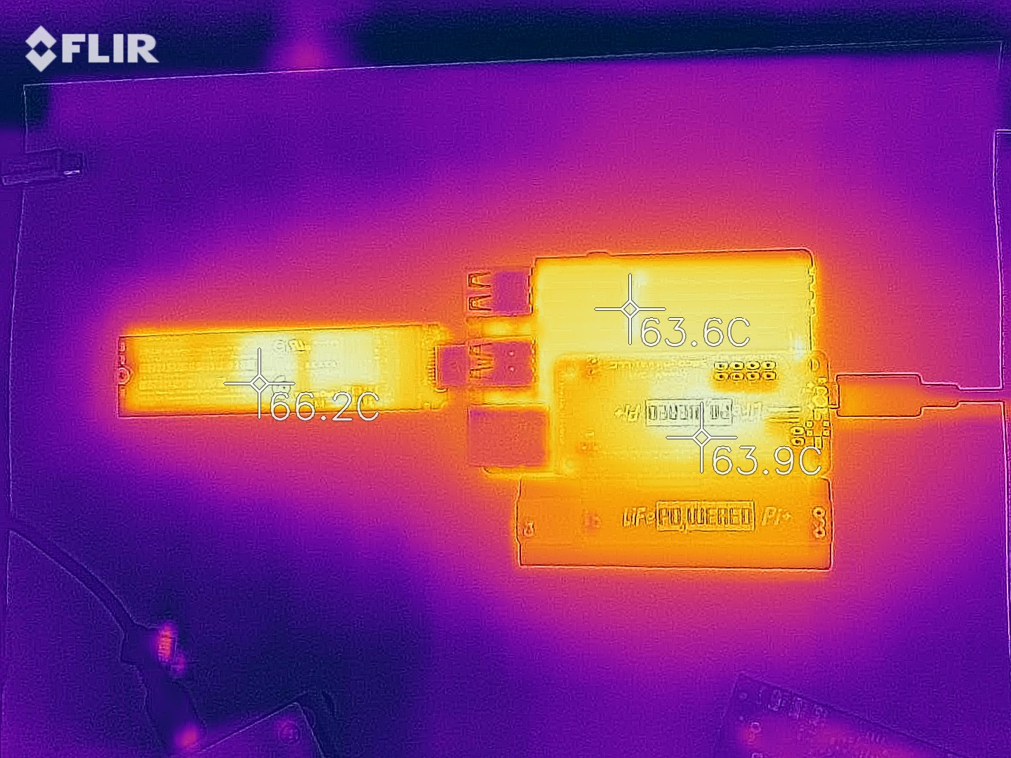
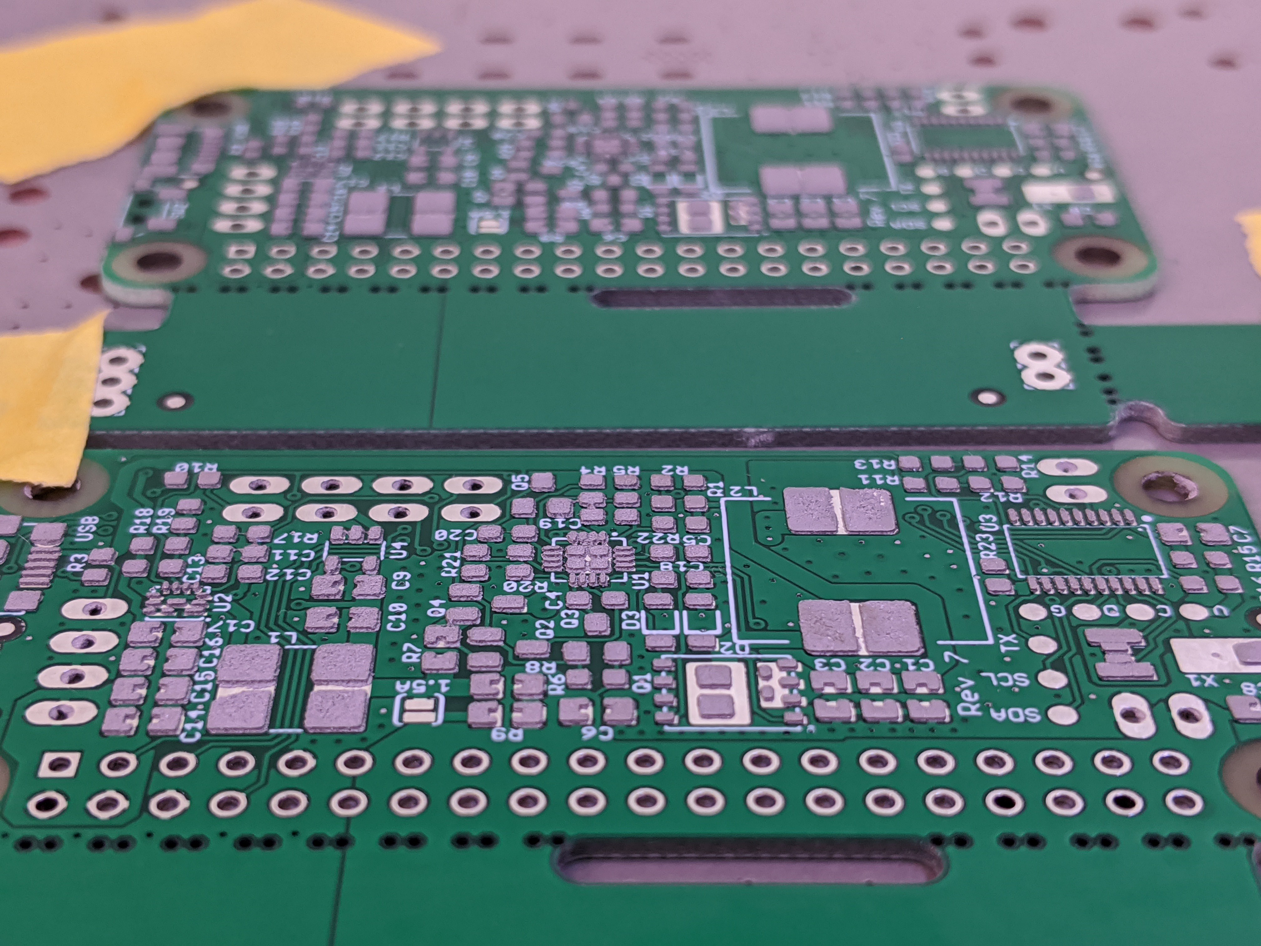
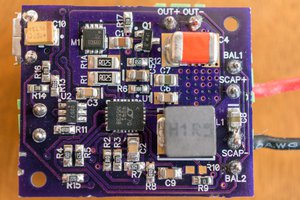
    Very nicely packaged. And good quality product. I have not run into too many issues after testing and final assembly of several hundreds of these boards. I had one board that needed reflow of the TPS61236P boost converter. A couple of panels had this weird issue where the mouse bites to separate the boards weren’t all drilled:

    And there was one board that had some cosmetic damage:

    But overall, production has been running smoothly. The red light issue fix I implemented on the revision 5 boards seems to have completely solved that problem, which is a relief. Demand for the product is looking good and with the quality boards we received we are able to keep up with it comfortably.

  • Raspberry Pi 4 Compatibility

    Patrick Van Oosterwijck07/03/2019 at 16:50 0 comments

    With the surprise release of the Raspberry Pi 4, I started receiving questions about compatibility with the LiFePO4wered/Pi+. Here’s what I found out!

    Surprise Raspberry Pi 4 release

    Like most people, I hadn’t really expected to see a next generation Raspberry Pi until next year. Unlike most people, for whom a new Pi release is invariably a delightful event, I experience them with some trepidation. I don’t have any special relationship with the Raspberry Pi Foundation. On the contrary it seems sometimes, since they studiously refuse to acknowledge the existence of my hardware, talk about it, or promote it in any way while they’ve done so repeatedly for my competition. So I have no advance warning, and when a new release drops, I need to scramble and find out if the new thing works with my existing hardware or if my stock suddenly has become significantly devaluated.

    In this case, the release happened on June 24 and I finally managed to pick up a unit from Micro Center on Friday June 28. I had some reasons to be worried since the new recommended power supply for the Pi 4 is a 5V/3A USB Type-C, and early reports indicated the new Pi to be a power hog. So I did some testing over the weekend.

    Testing the LiFePO4wered/Pi+ powering a Pi 4

    The first thing to check was whether the host software would work on the new Raspbian Buster which is required to support the Pi 4 hardware. On that front, everything went smoothly: the host software works just as it did before, and I had the system running from the LiFePO4wered/Pi+ in no time.

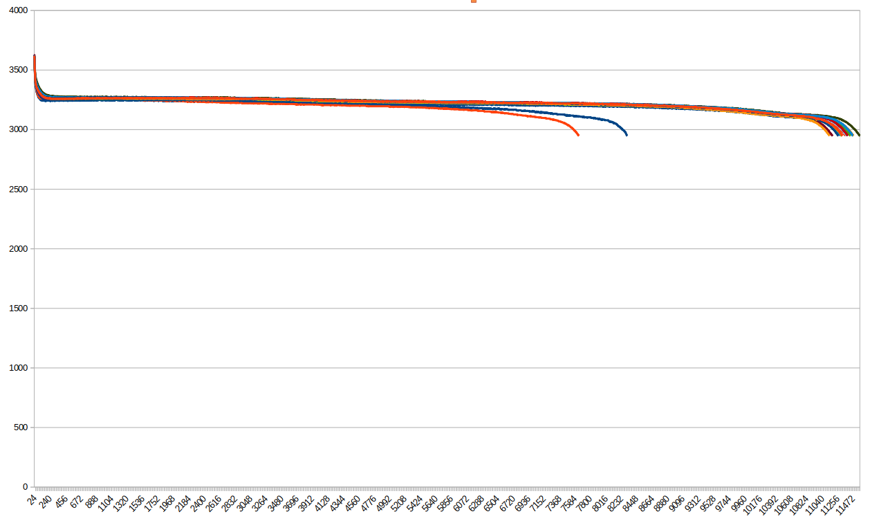
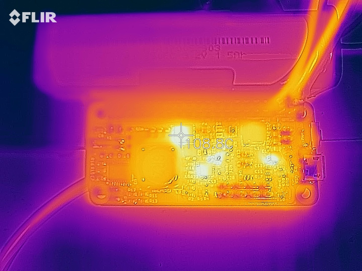
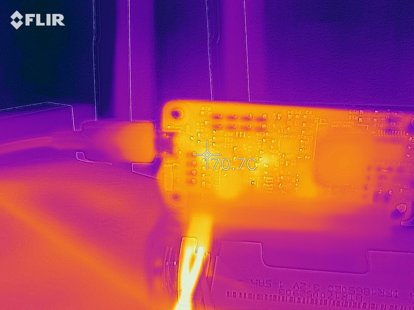
    Then came the time to put some load on it. I used the stress utility to load the CPU, memory and I/O subsystem and ran continuous YouTube videos playing full-screen to add some load to the GPU. I also connected a USB hard drive for good measure, while I already had a backlit USB keyboard and mouse connected as well. I kept this running for over a day, with no issues other than that the system indicated with the on-screen thermometer icon that it was thermally throttled. The LiFePO4wered/Pi+ had no issue charging the battery (I was using a 3A charger) and reported a load current to the Pi of about 1.5 A. Since the LiFePO4wered/Pi+ is rated for a continuous output current of 2 A, this presented no issues, other than heat, as the thermal image below shows:

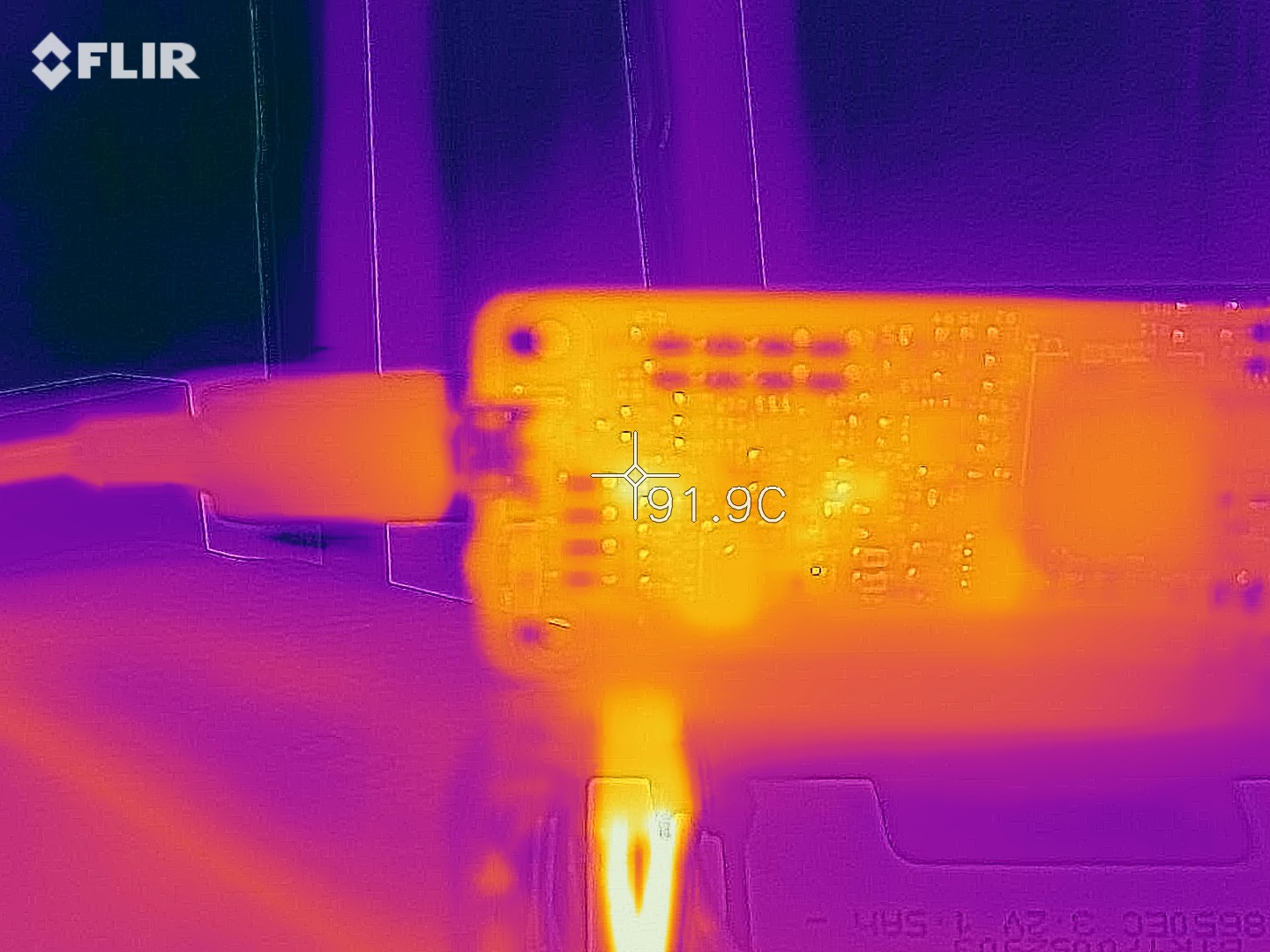
    Both the Pi 4 CPU and the LiFePO4wered/Pi+ settled at a temperature of around 90˚C. When using a system like this at high load, it would obviously be wise to add cooling, but for testing, we like to abuse things. :)

    All this testing had been done with the LiFePO4wered/Pi+ plugged in, which is the thermal worst case since the charging system adds its own heat. Now it was time to test whether the system could run from the battery and survive the transition from external power to battery power, which oddly some competing so-called “UPS”es have trouble with.

    Below is a YouTube video of how that worked:

    No issues! The system runs through the transition as if nothing happened, which is how it should be. I didn’t do a battery run-down test yet, but based on the load current I’m seeing, the 18650 battery should be able to keep running for about 15-25 minutes from battery power at this load, before initiating a clean shutdown and cutting power when shutdown is finished. The 14500 battery is not recommended for a high-power system like this and will likely not work reliably. If you need longer run-times, the LiFePO4wered/Pi+ can of course be used with a large external 3.2V LiFePO4 battery as well, and then it just becomes an issue of how much space you have available.

    I will continue to do more testing, but it looks like the LiFePO4wered/Pi+ with 18650 battery is good to go for powering Pi 4 based systems. The only exception may be systems under super high load doing AI, GPU encoding at the same time with multiple high power USB devices attached, but I haven’t been able to make my Pi 4 draw that much current...

    Read more »

  • Fixing the "red light" issue

    Patrick Van Oosterwijck05/10/2019 at 19:19 0 comments

    Since I was running out of bare boards from the second production run of 1000, and I was intending to do another run of 1000 built completely at PCBWay, I needed to have a solution for some problem that had popped up in some units from the second production run: the "red light" issue.

    "Red light" issue

    Some boards were returned because the red CHRG light would come on (though usually very faintly) even if the battery wasn't being charged.  None of the units from the first batch of 300 ever exhibited this issue, but either having a different batch of components or just the higher volume made this pop up in a couple percent of units of the second batch of 1000.

    For users who mostly use the LiFePO4wered/Pi+ as a UPS the issue isn't really a big deal, but for shelf life and users who use the LiFePO4wered/Pi+ in sleep mode it would be a big deal since it would increase the power consumption in sleep more from around 5uA to several hundred uA.  I really didn't want to build another 1000 units that could have this problem, so a fix was urgent.

    "Red light" fix

    It took a while to come up with a good solution, but I’m pretty sure I figured one out. I reworked 10 boards that had been returned for this reason with my solution, and they all ended up working fine.

    The problem existed in the circuitry I was using to disconnect the charger from the battery when not charging to reduce leakage current. I use three MOSFETs to do this, and in the old circuit they were driven through dual diode D1 from the CN3801’s CHRG and DONE pins:

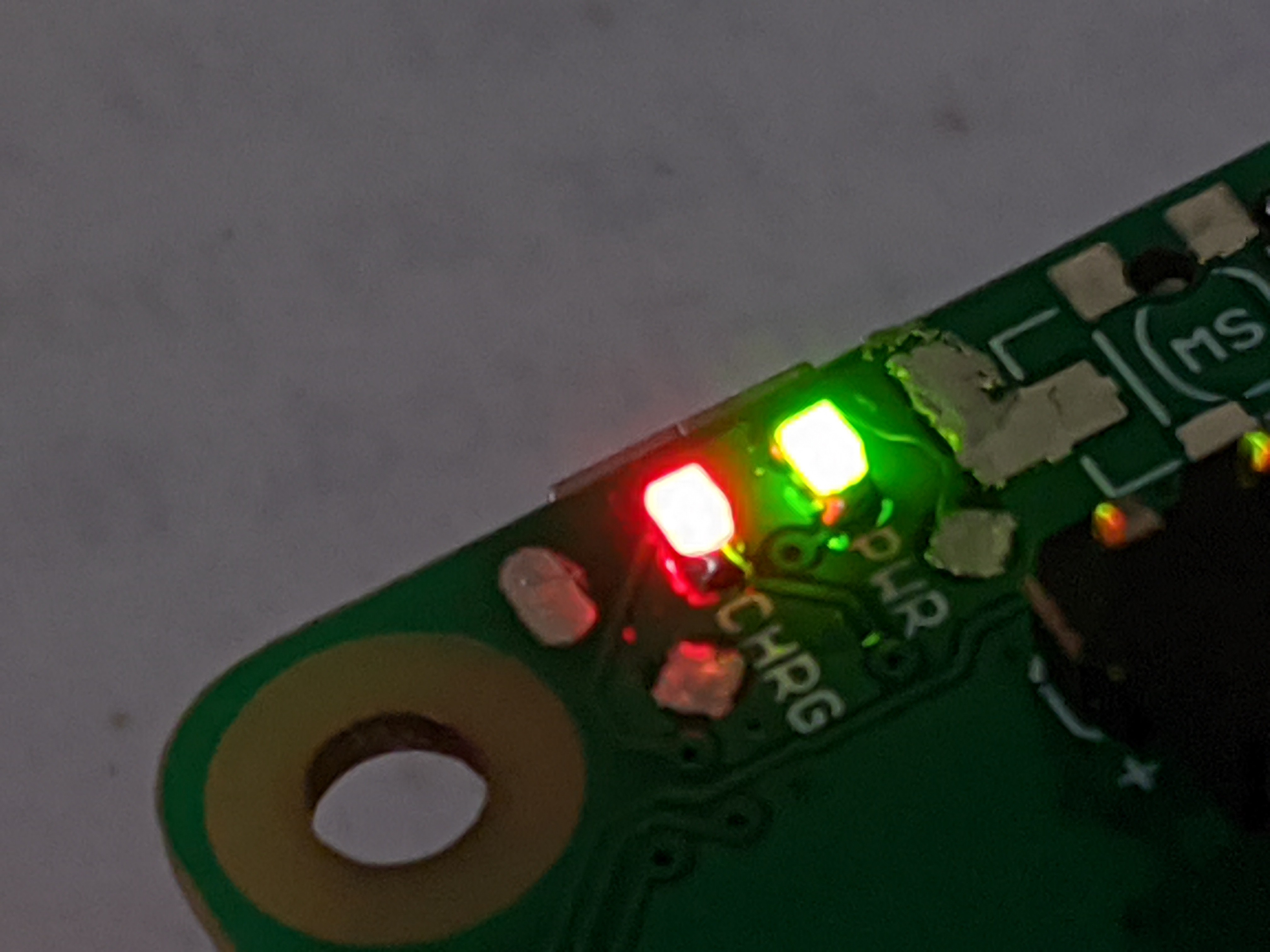
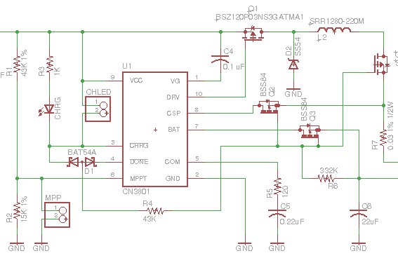
    In all the LiFePO4wered/Pi3’s and the early LiFePO4wered/Pi+ batch I made, this always worked as expected. The CN3801 has an under voltage lockout at 3.8 V nominal, 3.1 V minimum, and my assumption and experience up till then was that this would keep the CHRG and DONE pins from turning on when the only voltage powering the CN3801 was battery voltage leaking back to this circuit through the diode drop of Q1’s body diode. The pass transistors would be turned off and the circuit would not leak back to the charge input.

    But what I’m learning as I’m scaling to higher volumes is that you always run into new unexpected issues as you scale up. When you make 10 prototypes that work great, you will probably run into some 1 out of 20 problems when you make 100 units next. When you have fixed those problems, your next 1000 unit batch will still have some 1 out of 200 problems. And so on. The upside is that the circuit and your yield improves with every step in this cycle until it is high enough you can live with it. Of course, this also depends on component batches etc., so you might have a 1 out of 200 problem even after you’ve done a batch of 300 previously as was the case here.

    In this case it seemed that not all CN3801’s would keep their CHRG pins from turning on in the under voltage condition. To be honest, the spec never said that they would, this had been an assumption on my part confirmed by experimentation on an apparently too small number of samples. I have now changed the driving circuit for the MOSFETs to what’s shown below:

    The circuit with zener diode and pre-biased transistor doesn’t depend on variations in the CN3801 anymore. Instead it depends on variations in the zener and transistor thresholds. Which can be just as problematic of course. But I think I’ve calculated the tolerances well enough to be pretty confident it will work as expected. Being based on a current driven device like an NPN transistor with pull-down on the base has the added benefit that it presents a bit more load than the purely MOSFET based circuitry I had before, which could more easily be turned on by small leakage currents.

    Thanks to the use of a pre-biased transistor, the new circuit fits where the old one was so from a user perspective nothing will be different in this revision, and hopefully the "red light" issue will be a thing of the past. :)

  • Production progress

    Patrick Van Oosterwijck05/10/2019 at 19:01 0 comments

    Oof, I really haven't been keeping up with updates here.  Too much to do, sorry!

    When I wrote the last project log here, the Crowd Supply campaign was still going on, yikes!  That's been a while.  Since then, the campaign got successfully funded (including pre-orders over 500%!) and I've been scrambling to meet demand.  Since last week, finally all backer rewards and pre-orders were filled.  Crowd Supply decided to stock the LiFePO4wered/Pi+ and now I'm hard at work to build up their stock.

    If you want to catch up on what's been happening, I did write a bunch of project updates over on Crowd Supply:

    https://www.crowdsupply.com/silicognition/lifepo4wered-pi-plus/updates

  • Watchdog feature guide

    Patrick Van Oosterwijck08/28/2018 at 23:51 0 comments

    The Crowd Supply campaign is going very well!  Already over 200% funded and still 21 days to go, yay! :)

    As part of the campaign I'm supposed to post useful or interesting weekly updates.  This week I decided to explain a feature that may cause some confusion: the application watchdog.  Since it's not related to the campaign per se, but explains a feature, I decided to reproduce it here as well.  Enjoy!


    If you are an applications developer for embedded systems, sending your solutions to remote locations where they can’t be reached for reset or service, this update is for you.

    The LiFePO4wered/Pi+ has many helpful features for different use cases. Some people like to use the on/off button to boot and shut down their Pi, while others turn on auto-boot and/or auto-shutdown to get on/off behavior based on external power for their application. The wake-up timer feature is really cool and helpful in low power, low duty cycle applications, and it’s pretty easy to understand what it does and how to use it.

    One feature that people have more trouble with is the application watchdog. Unless you come from an electronics or embedded systems background, you may not be familiar with what a watchdog is or does. So in this update, I’ll explain what it is, why you want it, and how you can use the one provided by the LiFePO4wered/Pi+ to make your Raspberry Pi-based project more reliable.

    The Wikipedia article on watchdog timers explains that a watchdog timer is “an electronic timer that is used to detect and recover from computer malfunctions.” Let’s face it: computers are complicated beasts with many moving parts that all need to work correctly. There will always be bugs (or cosmic rays) that will cause something to act up at some point. If your computer is on your desk, you can reboot it when this happens, but what if you are using a computer like a Raspberry Pi in an embedded system? What about in something that needs to run automatically and reliably, may be hard to reach inside a machine, or is located far away in a remote location? The Wikipedia article notes that “watchdog timers are essential in remote, automated systems,” giving the example of a Mars rover. If your Mars rover’s computer crashed, who would go reboot it?

    Watchdog timers are usually extremely simple, and this is a good thing. It’s the complexity of computers that makes them susceptible to crashes and hangups, so it makes sense that the system that watches over them should be less susceptible to these issues, hence simpler. Ideally, watchdog timers are implemented in hardware. In the LiFePO4wered/Pi+, the watchdog is implemented in firmware. Not quite as desirable as hardware, but if you compare the complexity of the firmware on the LiFePO4wered/Pi+ (4 kB) with that of the Linux system running on the Pi (4 GB), it’s orders of magnitude simpler.

    The basic concept of a watchdog timer is that the software running on the system needs to regularly reset the timer (commonly referred to as “kicking” or “feeding” the dog, depending on how you feel toward dogs), because if you fail to do so, it will reset you instead (the dog will “bite” you) when the time runs out. This ensures that if your system hangs, it can be reset and brought back to a responsive state.

    In the LiFePO4wered/Pi+ implementation, by default the watchdog is off (WATCHDOG_OFF or 0). This is because it’s conceived as an application watchdog: it’s not just there to ensure the Linux system is up, but also to ensure that whatever application you are running is behaving as it should. So how you implement this is up to you as a developer and depends on what functionality is critical to your application.

    The watchdog can be set to two levels by writing to the WATCHDOG_CFG register. The first level, WATCHDOG_ALERT (1), is useful during development or when the Pi system is within view of an operator who can take action....

    Read more »

View all 31 project logs

Enjoy this project?

Share

Discussions

goger wrote 10/21/2022 at 13:52 point

I have a problem with my LiFePO4wered/Pi+. It worked fine for about 6 month, already saving me in one power out. But now the battery (the big variant) doesn't seem to get loaded anymore when the raspberry is connected. I found this out because the rapsberry was shut down this morning. I removed the LiFePO4wered/Pi+ and could load it using a usb power supply without a connected raspberry. but after connecting to the pi again, it seems like the battery just doesn't charge. The red LED stays on all the time. This was not the case before, it was shut down from time to time. Regarding power, the IOUT reads about 500mA while the input power shown by my UM25C is 0,3 to 0.4W. The red LED is on but with this power the battery cannot be charged. Can anyone advise what to do? Is the device broken?

  Are you sure? yes | no

sean wrote 08/19/2022 at 04:19 point

My LiFePO4wered/Pi+ has been working great for a couple of years now. Thanks! Finding a replacement battery can sometimes be a challenge, though. Will a Titanium Innovations 18650 Battery - 2600mAh 3.7V Lithium Ion (Li-Ion)  work?

  Are you sure? yes | no

bmsmith.ford wrote 08/05/2022 at 20:19 point

What resistor do I use if my panels are 5V, 0.5A, 2.5W panels and don't list an MPP voltage?

According to https://en.wikipedia.org/wiki/Maximum_power_point_tracking#Constant_voltage, the MPP can be approximated as 0.76*V_oc which gave me 0.76*6=4.56V. The problem is when I plugged that into the formula to determine what resistor to use it gave me 51815/(4.56-4.66) = -518 kOhm resistor which doesn't sound right. I'm trying to power a raspberry pi zero w with these panels. https://www.amazon.com/dp/B074TYH68Z?psc=1&ref=ppx_yo2ov_dt_b_product_details

Since the panels are 5V and the Pi Zero w needs 5V, can I just not use a resistor on the LiFePO4/Pi+? I have 4 panels and I was gonna hook them up in parallel, so that would be about 5V 2A into the LiFePo4/Pi+

  Are you sure? yes | no

dragon tigi wrote 05/01/2022 at 20:21 point

Is the LifePo4wered pi+ compatible with Rock Pi 4 (model B)? Or are there things to take in consideration when using it with this type of board.

  Are you sure? yes | no

tyeth wrote 02/10/2022 at 16:37 point

Hey Patrick, got the 4+ version a few years ago with the crowd funding, well done for keeping it all going. I've used it for a few things (3d printing, mobile sensor prototype, presentation/event occupancy iot device), it's fantastic, but now I'm trying too much and I need to both get another and think of a cunning plan... On the subject of buying a new one I notice you've updated the design a year ago (resistor), has that made it to production/tindie yet?

 I'd love to see some way of having multiple cells safely (I'd feel a fool just paralleling 6 of them although I'm sure it would work short term it would surely charge slowly and imbalanced cells would damage all of them - obviously I'd start with new cells but still).

My current need (https://www.hackster.io/tyeth/bird-feed-dispenser-for-floor-foragers-5335e3) is prototyping a bird seed dispenser, effectively a pi-zeroW with servo + 3-6V hobby motor, servo opens seed chute which points at spinning plate on motor (like at the back of a salt/grit spreading truck for road safety in winter). There's a 10000mAh powerbank with 2 outputs (lifepo4 and servo+motor), with pass-through support (charge at same time), and a really poor solar panel (5v 200ma) and it's winter still here in the UK. The issue is the power bank shuts off without enough drain. Using the solar attached it works with lots of sun, or with barely any it almost freaks-out (first and last of four lights) or resets the bank, or stays off, so what I'd love is the ability to have both solar and the usb input. For now I plan to sever the 5V lines from usb to servo+motor and lifepo4+ with a latching DPDT relay to try to allow the hotplugging and re-enabling the powerbank. 

To be honest it's not important as once I'm happy I'll hopefully move it over to an ESP32 and deal with it another way, along with 3d print something rather than a hand-fan mounted to a wooden stick, but I imagine you know how permanent a temporary fix can be - it's only the usefulness of the lifepo4wered+ that makes me want to make the esp version, so thanks again for the design/device/time.

  Are you sure? yes | no

Patrick Van Oosterwijck wrote 02/10/2022 at 21:32 point

The version with stackable header is rev 7 in all channels, it has the lower current sense resistors and synchronous rectifier charger.  Balancing is automatic for cells in parallel, you just need to make sure they have the same state of charge when you connect them together but after that they work as one larger single cell.  It's when you put cells in series that balancing needs to be taken care of.  I'm working on some future technology to do that (https://hackaday.io/project/178287-lifepo4wered-bms).  Your solar panel will need to be significantly bigger if the Pi needs to always run.  If not and a timed system works for you, you can use the wake function of the LiFePO4wered/Pi+ to significantly reduce the energy requirement.  Not sure about the added power bank, is it made for solar charging (MPPT)?  If not, you're much better off just using a larger LiFePO4 or several in parallel with the LiFePO4wered/Pi+ since you can add an MPP resistor to do efficient solar charging.

  Are you sure? yes | no

tyeth wrote 02/11/2022 at 12:12 point

Aha brilliant thank you so much. I kind of assumed paralleling the cells would balance but not keep each one at peak condition like individually balanced series ones are kept, and not sure how much the life would be affected (how long is a piece of string).  The powerbank is not intended for solar, so your suggestion to increase cell count and wire directly makes sense. My concern is the mppt resistor setting would be so unreliable/variable for me as the house blocks midday sun and it's so low at the moment (a solar novice but read about the different mppt techniques). I've got a couple of 6-12volt panels ~0.2<->1W one has a 5v regulator already so I wondered about leaving that attached to the LiFePO4wered/Pi+. I imagine the best option is as you mentioned a blank panel directly to the LiFePO4wered/Pi+ with the MPP resistor set appropriately and maybe 4cells. You'll be relieved to hear I am using the shutdown/RTC wake timer, it's fantastic and combined with the node-red sun calculations I can wake and feed the birds then sleep for a few hours, repeat until sun is down then shutdown  timer changes from a few hours to until golden hour of dawn. Maybe I need to buy the version without cells too then and help support the cause ;)

  Are you sure? yes | no

Patrick Van Oosterwijck wrote 02/12/2022 at 00:00 point

The MPP does not vary much with the lighting conditions, it tends to be fairly constant for a particular solar panel.  Once the MPP voltage is configured correctly, the amount of current drawn will be automatically adjusted to the available light.  Do not use the panel with 5V regulator, it will interfere with the MPP regulation doing its job.

  Are you sure? yes | no

Leesam wrote 11/04/2021 at 20:38 point

If this were used with an external battery that could handle high current, what's a safe maximum amperage you could pull  from the switched battery output, VBSW?

  Are you sure? yes | no

Patrick Van Oosterwijck wrote 02/10/2022 at 21:16 point

It's switched by an AP22802A load switch, which has an over load current limit of 2.2A to 3.2A, 2.7A typical.  Keep in mind that this also increases the load on the battery so there will be more IR losses and the battery voltage as seen by the circuit will be lower which may make the unit shut down more quickly.

  Are you sure? yes | no

KingMackerel wrote 05/26/2021 at 15:35 point

Thanks for creating this great solution. I just ordered one from Tindie. I'm going to use it in a project with a Pi-Zero W and a VHF transceiver. I'll let you know how it goes. 

  Are you sure? yes | no

davedarko wrote 06/16/2020 at 08:59 point

Hi Patrick,

it has been a while since the crowdfunding campaign, but the project I was buying this for got cancelled and just yesterday I came around to connect this and the smaller version to a Raspberry PI zero. Sadly both won't start up the PI zero, they show a charging light but the power LED stays dark no matter how long I push the button and the PI does not turn on. The software is installed on the PI. Do you have any trouble shooting guides I can follow? Are there any modifications for the crowdfunding that I could have overlooked since this is two years old? Anything I can do to test it on it's own?

thaaanks

  Are you sure? yes | no

Patrick Van Oosterwijck wrote 06/16/2020 at 16:25 point

Hi Dave,

First thing I would try is remove the battery for 10 minutes (yes that long to be sure), put it back, see what happens.  Do this after you have fully charged the battery first (the red charging led turns off).  If the cell is deeply discharged, charging may take a while because the charger will be pre-conditioning at a low rate.

It's possible that after sitting idle for this long, the battery got deeply discharged.  The unit only takes 4 uA while sleeping, but that plus the cell's inherent self-discharge may be enough to discharge all the way after sitting without input for years.

  Are you sure? yes | no

davedarko wrote 06/16/2020 at 18:19 point

Awesome, removing the battery worked! I tried that before, but not that long - thanks!

  Are you sure? yes | no

fuchsiv wrote 02/11/2020 at 22:47 point

Hi Patrick,
this UPS seems really great. A few questions:
- can the LiFePO4wered/Pi+ be powered by a solar cell AND an external power supply at the same time?

- I have seen there is a 5V connector at the PCB.
I have a own developed HAT over which my Raspberry Pi is powered.
Can I still power the Raspberry Pi over my HAT (by the 5V connector), instead of powering directly over the LiFePO4wered header?

Thanks
Markus

  Are you sure? yes | no

Patrick Van Oosterwijck wrote 02/12/2020 at 15:52 point

Hi Markus,

On the board itself, the USB input and VIN pads are tied together and only one is to be used at a time.  External power and solar input could be supported externally by diode ORing them, as long as the MPP voltage and the input voltage are expected to be similar, and the MPP is set suitably to work with either.

The LiFePO4wered/Pi+ needs control of the Pi power, so it doesn't work if the Pi is powered from its own power input or another GPIO source.  Your circuit would have to connect to the LiFePO4wered/Pi+ USB or VIN pads instead.

  Are you sure? yes | no

fuchsiv wrote 02/16/2020 at 10:39 point

Hi Patrick,
thanks for your answer.
I have to detail my second question more:
What I'm still wondering, can I disrupt the connection between LiFePO4wered/Pi+ (RPI header pins 2 and 4 at your circuit) and the RasPi header?
The energy flow should be this way: LiFePO4wered/Pi+ VOUT ==> my circuit ==> RasPi USB 5V power
Otherwise the header would shortcut my circuit.
Is this possible? If not, maybe I can cut the lines at the LiFePO4wered/Pi+ PCB.

  Are you sure? yes | no

Patrick Van Oosterwijck wrote 02/17/2020 at 17:54 point

Yes, with your own wiring assembly this is possible.  Of course at that point, the LiFePO4wered/Pi+ can't guarantee a clean system shutdown anymore since your circuit can kill the power without the LiFePO4wered/Pi+ knowing about it.

  Are you sure? yes | no

Maikel.egberink wrote 12/14/2019 at 14:20 point

Hi Patrick,

My current LiFePO4wered config is already running like a charm for almost two years, thanks again.

Now that I’m gonna order one of these soon for a new home-automation project I have a small question. Could you verify it’s also working for a rpi4?

  Are you sure? yes | no

Patrick Van Oosterwijck wrote 12/15/2019 at 04:58 point

Hi Maikel,

Yes, as long as the total current consumption is 2 A or below.

  Are you sure? yes | no

Maikel.egberink wrote 12/15/2019 at 18:19 point

Thanks for the confirmation Patrick, I thought so. I will make sure. 

  Are you sure? yes | no

Kai wrote 12/03/2019 at 13:24 point

Hi Patrick! I bought the lifopo4weredpi module some months ago and it's working really well for me. It protects my home Automation pi from power adapter failures. Being a RC Pilot, I'm Always concerned About battery life. I wondered if there might be a possibility to tell the lifopo4weredpi module to run on battery while powered to "cycle" the battery to a given Level, then reloading it. I know, this might come with the possibility of not having enough backup power in case of a power outage… If it helps to keep the battery fit, this would be a great thing. Kind regards, Kai   

  Are you sure? yes | no

Patrick Van Oosterwijck wrote 12/03/2019 at 15:29 point

Hello Kai,

Thanks for the suggestion!  I cannot do this with the current hardware as it's a stand-alone charging chip, but I'm working on new technology that integrates charge control into a microcontroller and it should be possible to do it there.
This new technology is currently being developed in the #LiFePO4wered/ESP32 project, but the plan is to migrate this into a future Raspberry Pi unit once it's been proven.

  Are you sure? yes | no

Kai wrote 12/03/2019 at 20:14 point

Hello Patrick,

thanks for your reply. This ESP32-based project looks very interesting. I'll follow it too.

  Are you sure? yes | no

Matthias Urlichs wrote 09/03/2019 at 17:23 point

Nice, the heap of lifepo4wered modules I have are working flawlessly so far.

One firmware enhancement request, though. Sometimes I need to re-init a pi from scratch, i.e. no daemon to keep the lifepo4 alive, i.e. crash halfway through the re-installation.

Idea: when that is imminent, flash the LED for some configurable time (default zero = feature disabled), and abort the shutdown if the button is then pressed.

  Are you sure? yes | no

Patrick Van Oosterwijck wrote 10/01/2019 at 17:34 point

Hi Matthias, thanks for the idea!  I'll have to think about this.  The problem is: how does the LiFePO4wered/Pi+ know that this is because you're reinstalling?  This is not necessarily behavior I want to have at other times, since it may make the boot timeout useless for its normal purpose.

Maybe it would be better to just have a longer timeout on boot?  It is adjustable, but maybe the default should be longer?

  Are you sure? yes | no

Matthias Urlichs wrote 10/02/2019 at 04:58 point

This is why I said I'd not do anything different except when I press the button. The boot timeout should be as long as it is anyway, but ten seconds before the LiFePo4+ would take the power down you switch the LED to fast-flashing, and when I *then* press the button you re-start the timer.

  Are you sure? yes | no

Patrick Van Oosterwijck wrote 10/02/2019 at 21:13 point

The problem is that one of the main reasons I implemented the boot timeout was to prevent problems with units being on or having run out of battery when they arrived because the button was somehow pushed during shipping.  This makes me nervous about canceling the timeout with a button push as it may make the timeout ineffective in one of its main uses.

  Are you sure? yes | no

turnkit wrote 11/27/2018 at 09:26 point

Motion >>> WAKE, stillness for five minutes >>> SLEEP ???

Any chance that functionality could easily be added???

  Are you sure? yes | no

Patrick Van Oosterwijck wrote 11/28/2018 at 02:56 point

If you create a circuit that generates a >2s pulse from a motion detector and connect that with an open collector/drain to the BTN input, you might be able to make that work. :)

You'd probably have to add some lockout that inhibits the fake button press if Vout is present.

  Are you sure? yes | no

dion wrote 07/06/2018 at 02:16 point

Patrick,

I'm following this project with interest. It looks close to fruition which is terrific.

One query I had that may well have been covered though I've simply not delved deeply enough in the text here; if following a period of UPS function the battery depletes and the system shuts the Pi down in an orderly way, is there provision to reset the Raspberry Pi via the lifepo4owered/pi+ board when external power is re-enabled, and/or to remotely re-start the Pi when external power returns?

Dion

  Are you sure? yes | no

Patrick Van Oosterwijck wrote 07/28/2018 at 02:37 point

Hello Dion,

Yes, you can enable the AUTO_BOOT feature to make it work this way!

Patrick

  Are you sure? yes | no

James Christie wrote 03/08/2018 at 10:07 point

Hi Patrick,

I've been following your work for some time, and am excited by the upcoming lifepo4owered/pi+ 

I am hoping the lifepo4wered/pi+ is appropriate for my project.  It's a remote raspberry-pi based audio recorder for birdsong and the like.  I recommend a USB power bank which gives 5 days, or a car battery which gives 45 days (permanent 24/7) recording.  There is big demand for a Calendar mode, so people can record only at certain times (eg the dawn chorus).  I'd like to ask the following:

1 - You are introducing a RTC (yet I don't see one on the components list?).  Will that RTC be available via /dev/rtc in the usual way?  I need to set system time from RTC at boot (while in the forest, so no net access).  Obviously the RTC needs set once after purchase, which is currently achieved by simply booting with a net connection (headless) and waiting for a few mins until systemd's thing picks up net time and sets the rtc and system time.  Will this workflow have to change?

2 - when running normally (power bank providing power), does the lifepo4powered/pi+ waste much of the power?  Specifically, I hope the current doesn't go into the 18650 and back out.  Every mAh is valuable to me. Also, some powerbanks "time out" if they see no current draw for a time (30s or so).  My standard current draw is 70mA (pi A+), and that's enough to keep most powerbanks alive.  However, I expect to see my powerbank time-out and power down when the pi is powered off (awaiting a timed reboot from the lifepo4wered/pi+). At that point, I guess the powerbank suddenly sees a demand (on it's USB output) and _might_ provide power, depending on the particular powerbank's design.  I could probably simulate this situation by : calling "poweroff", wait for the pi to shut down, then wait for the powerbank to timeout, then disconnect and reconnect the power to the pi, and seeing if the powerbank is triggered to turn on again.  Am I thinking about things correctly here? If the powerbank needs a physical button-press to get it going again after time-out, I'm stuffed, right? What a cumbersome question, sorry.

3 - Can I assume a sensible scriptable interface to the reboot-timer.  I'd like to call something like "lifepo4cfg set reboot-time 0500 2018-03-02", or "set sleep-time 10 hours", then call "shutdown" (or something), and have it reboot.  Is this roughly right?

4 - I currently provide users with a custom ".img" file to flash onto their sd-card.  They can drop a few config files into /boot/ to set volume levels and other things.  Can you imagine that I can have a "LIFEPO4=yes" in such a config file, which will allow me to script any loading and configuring the lifepo4 stuff (insmod for the i2c RTC, and whatever else), or might there be tangles there?  Apart from the initial setting of the time on the RTC, I need these things to work straight from a flashed SD card. (might there be access to a bit in the RTC eeprom I can use to flag whether it's been configed before? - RTCs sometimes have some spare bits).

5 -  Currently, standard operation is to allow the recorder to run out of battery and turn off with no clean shutdown (argh).  Wtih the lifepo4powered/pi+ I understand that shutdown will be clean, but will the RTC's clock time be retained (from power from the 18650?) after this?  Normally the operator arrives at the unit (in the forest), changes SD-card, and changes battery and restarts the system to resume audio recording.  I hope that the clock doesn't need reset after being fully run-down.

That's the end of the questions - phew. 

Finally - people might be confusing the lifepo4wered/pi with the lifepo4wered/pi+ project on hackaday because they URL looses it's "+" sign. But perhaps you know that:

https://hackaday.io/project/20909-lifepo4weredpi   (this one - lost it's + sign)

https://hackaday.io/project/9461-lifepo4weredpi  

Thanks in advance.

James.

  Are you sure? yes | no

Patrick Van Oosterwijck wrote 03/24/2018 at 23:45 point

Hello James,

Sorry I didn't see this earlier, I hope you will get some notification that I wrote an answer!  Here it goes:

1. It's an RTC function, not an RTC chip.  The micro has a 32 kHz crystal connected and in tandem with the host daemon implements what's needed to save the system time on shutdown and restore it on boot.  There won't be a /dev/rtc device, and it has no temperature compensation as fancy RTCs have, but it will be sufficient for many uses.  Testing indicates that you might deviate a second or so per day.

Note that if the system time is already very close to what the LiFePO4wered/Pi+ has kept track of, it will decide there's another system keeping time and won't reload the value on boot, so if you need a better RTC you can still add it and it will take precedence.

Also, your workflow to set network time etc should still work fine.

2. Unfortunately all power conversion wastes some energy, and so does the LiFePO4wered/Pi+.  If the battery is charged, the current doesn't go in and back out the 18650, but it still goes through the input (charge) stage and output (boost) stage of the circuit.  The charge stage has around 85% efficiency at high currents and the boost stage 90%, so the combined efficiency is around 75%.  This was tested at 2A load, I haven't done the experiment at lower load currents.

I should also note that the LiFePO4wered/Pi+ was designed to be able to remove the on-board battery area and connect an external (large) LiFePO4 battery instead, and some pre-release customers are using it that way.  By doing this instead of using a large external battery, you only need to consider the efficiency of the boost stage, which is around 90%.  You can also charge the big battery from a solar panel in that case, if that would be helpful.  On the downside, replacing the battery would clear your RTC time, unless you add a big cap in parallel with the battery.

Your procedure to test the behavior of your power bank sounds correct.  As long as the Pi is running, the LiFePO4wered/Pi+ will draw power from the input to power it, as long as power is present.  What happens when the Pi is shut down is the question, because when the battery is full, the LiFePO4wered/Pi+ will stop drawing current if the Pi is off.

3. The RTC wake time is set as a Unix time stamp, so a large number such as 1521934164.  Of course you can combine with other tools to make this more palatable such as "lifepo4wered-cli set rtc_wake_time `date +%s -d "3/25 10:00 am"`".  The rtc_wake_time register is for setting an absolute time to wake up, you can also still use the wake_time register which sets a relative number of minutes from the point when the system is done shutting down.  Performing actual shutdown is your responsibility.

4. That should be possible, but you can also just have the lifepo4wered-pi host tools installed and they won't cause any issue if no LiFePO4wered UPS is present.

5. With the LiFePO4wered/Pi+ added, a clean shutdown is performed and the RTC time is kept with the 18650 even if it's "empty"--there will still be plenty of charge to keep the 4uA micro running for quite a while on remaining charge.

And, yes, I know the + is missing from the URL, it's annoying but nothing I can do about it. ;)  On the plus side, the name meshes nicely with the new Raspberry Pi 3 B+ just released. :)

Again, sorry for not seeing this sooner and I hope it answers your questions.

  Are you sure? yes | no

James Christie wrote 04/25/2018 at 06:35 point

Patrick - thanks for this detailed reply - it gives me a lot to work with.  Cheers.

  Are you sure? yes | no

Steven Lu wrote 01/17/2018 at 21:15 point

I noticed that you mention that a power button (physical) will be employed this time (compared to the touch sensor on the non-plus). 

I support this move and hope that you stick to old school buttons. The other day getting off the train I tried to use the button to shutdown my pi but it did not respond to my finger at all. I have no idea if some combination of temperature or humidity is to blame, but considering how we care so much about the battery chemistry we should make such mundane components as buttons be as bulletproof as possible also.

  Are you sure? yes | no

Patrick Van Oosterwijck wrote 02/16/2018 at 23:17 point

Completely agree Steven.  The touch button was too sensitive to external factors such as static electricity that sometimes required it to settle whenever the "environment" changed.  No more of that.  This has a good old mechanical button facing the side, footprints for a button facing up and connections for an external mechanical button.

  Are you sure? yes | no

alanmcdonley wrote 10/01/2017 at 00:08 point

Hi Patrick,

You wrote: "I was intending to provide an option to lower Vout to 4.75V, because it will allow more output current. Can you expound on why you'd want higher Vout instead?"

With the existing LiFePO4wered/Pi3 unit running at Vout: 4958, cooled by the passive 15x15x15 heatsink, in the Tindie case (on 1/2 inch feet), a load factor greater than 2 will eventually report under-voltage throttling and/or high temperature throttling.  Perhaps a processing spike is trying to draw more current than the unit can supply causing the voltage to sag momentarily. Starting nearer the upper limit of the board spec 5.25 might offer me greater protection from these momentary voltage dips.

I read reports from some Raspberry Pi3 owners of under-voltage throttling when they ran at 4.75v (at the board).  Perhaps the voltage sensor on the Pi3, which supposedly triggers at 4.65v, is overly sensitive. 

Offering 4.75v as an option, sounds like it might extend the run time on battery as well.  Options are good.

The new unit with double the power sounds great. 

Regards,

Alan

  Are you sure? yes | no

Patrick Van Oosterwijck wrote 01/13/2018 at 00:47 point

Hello Alan,

You pretty much give the answer yourself as to why being fixed at 5V and removing the option to go lower makes sense.  The Pi will complain if the voltage is "too low". :)  And since modern Pi's all use switch mode power conversion, the voltage level won't make much of a difference in efficiency.  It would have made sense for the original Model B since it used linear regulators, but the LiFePO4wered/Pi+ won't physically fit on those anyway.

I don't think I need to provide more than 5V though because my power output is pretty "stiff", it hardly sags under high load, and I don't need to contend with long cabling as wall warts have to (that's why you see so many 5.1V and higher wall warts--they want to have 5V left at the end of the cable when pulling high current through it).

It is by the way a good idea to use higher-than-5V wall warts with the LiFePO4wered/Pi+ and /Pi3.  They do throttle the charge current if the input voltage falls below 4.65V, and since most so-called 2A and even higher wall warts do sag significantly if you try to load them that much, it's good to start as high as you can. ;)

  Are you sure? yes | no

Jay wrote 08/05/2017 at 13:37 point

Any new updates since the initial load test results you posted 06-22? I'm interested in using a Raspberry Pi as a hub for an environmental monitoring device and your design makes my plan for it much more practical. Interested to know how the 2 oz copper works as a heatsink vs the 1 oz from before!

Thanks Patrick!

  Are you sure? yes | no

Patrick Van Oosterwijck wrote 01/13/2018 at 00:37 point

Hello Jay,

Yes, finally I have new load test results from my latest board revision!  With some improved components, the new layout and 2oz copper PCB, the peak temperatures at high load are definitely lower (20°C lower I'd say).  And its hard to say for sure, but I do have the impression that with the 2oz copper the heat is spread more widely across the whole PCB.  But it's hard to say for sure because it's a different thermal camera, different color gradient, etc.  I just know it's supposed to be better due to physics. :)

  Are you sure? yes | no

x893 wrote 06/16/2017 at 09:19 point

Hi,

possible use TPS61089 ?

I have some problem with download schematic - can you publish info on github ?

Thanks in advance

  Are you sure? yes | no

Patrick Van Oosterwijck wrote 06/22/2017 at 19:41 point

That chip is more expensive than the TPS61236P I'm using, any particular reason for the suggestion?

Looks like the Hackaday.io CDN choked on the "+" in the file name of the schematic, I changed the name and now it seems to work.  Hackaday, fix this so it either works or tells me there's a problem when I upload the file!

Wonder if the "lack of schematic" made any different in the Hackaday Prize judging... :(

  Are you sure? yes | no

Antoine wrote 06/14/2017 at 08:35 point

Hello Patrick,

I have already purchased your LiFePO4wered-Pi3 ™ from Tindie.
Our prototype is based on Pi Zero W for AQI.
Now I have to select Solar Panels and there is a big gap between the average output panels (Vmpp 12V to 17V) and the LiFePO4wered-Pi3 ™ V.in Max (9V).
As you said, the MPPT is also less relevant for panels.


That's why this new version is very clever.

Our vote goes to You.

We keep in touch from South of France

  Are you sure? yes | no

Similar Projects

Does this project spark your interest?

Become a member to follow this project and never miss any updates