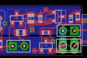
This is my attempt at a better 3D printer controller board. This is my first attempt at creating a fully realized product.
Specs:
3x 12-36V power inputs
3x Large (15A) MOSFETs, one for each power input
3x Small (7A) MOSFETs, one for each power input
4x Thermistor inputs connected to a 12-bit ADC
4-6x Stepper controllers supporting up to 3A steppers each
4-6x Endstop controlled by stepper controllers.
8x unused GPIO pins
1x SPI header/pins with dedicated CS (Raspberry Pi also supports using other GPIO pins as CS)
On board 3.3V and 5V regulators
USB Micro B - Male connector for providing power to the Raspberry Pi via the onboard 5V regulator
Supports Raspberry Pi 3 or Raspberry Pi Zero
Only 100m x 100mm
How its done:
Thermistors: I use a 12-bit ADC that communicates to the Raspberry pi via SPI
Stepper Controllers: The stepper controller I choose communicate with the Raspberry Pi via SPI and are chained together (using a single CS). Steppers are powered via the #1 power input.
Endstops: Each stepper controller supports a single switch which can be queried via SPI communications.
MOSFETs: I have added one large (15A with a XT30PW connector) and one small (7A) MOSFET to each power input (each input has a XT60PW connector) and created large copper filled zones to provide plenty of power to each.
GPIO: by using SPI to communicate with many of the components, there are still plenty GPIO pins left to do interesting things like controlling servos and whatnot.
What I need:
I really need someone with real electrical engineering expertise to review and correct/guide the design in the right direction. I am programmer and I am only self taught in electrical design. I *think* I have got it pretty close, but I want to get it solid (as is possible) before I build a prototype to start the software development on.
I plan on writing the software in Linux so it can run on one of the Raspberry Pi distros. I have also considered writing it in .Net as to leverage Windows 10 IoT, but I think that a Linux version would be more useful (at least to start with).
Anyone willing to help (either hardware or software) please private message me.

 Grégory Paul
 Extreme Electronics
 Jdaie
Jdaie
More information