 Dessislav Gouzgounov
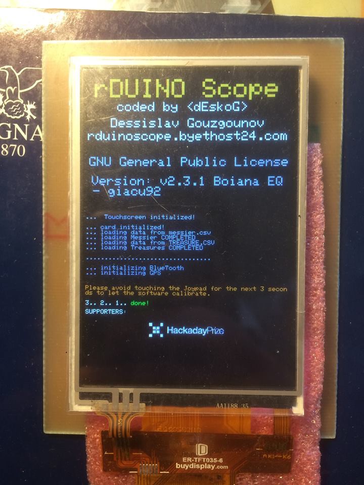
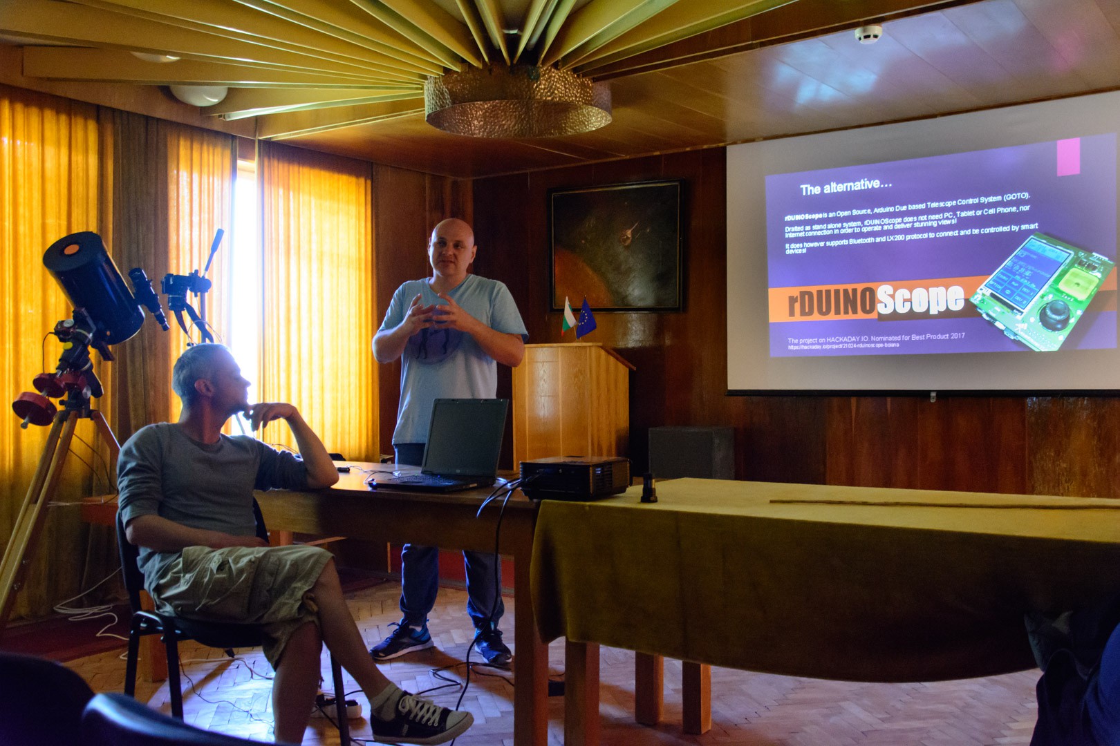
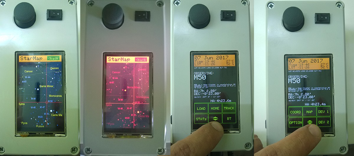
rDUINOScope is an Open Source, Arduino Due based Telescope Control System (GOTO). Drafted as stand alone system, rDUINOScope does not need PC, Tablet or Cell Phone, nor Internet connection in order to operate and deliver stunning views! It does however supports Bluetooth and LX200 protocol to connect and be controlled by smart devices!

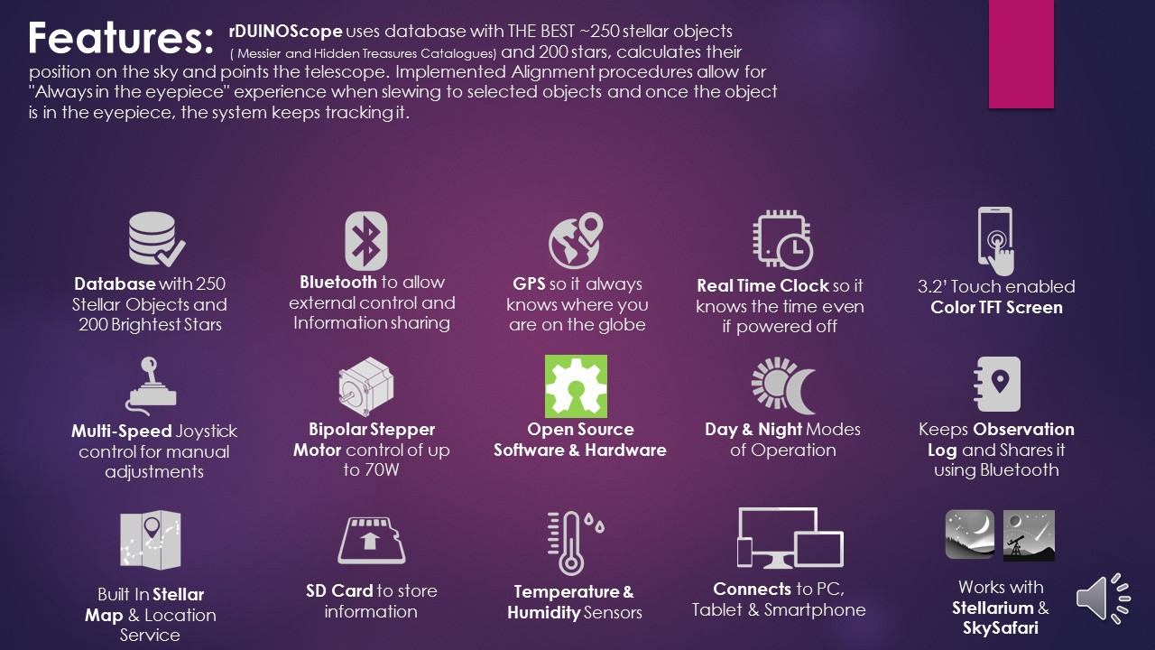
rDUINOScope uses database with THE BEST ~250 stellar objects ( Messier and Hidden Treasures Catalogues) and 200 stars, calculates their position on the sky and points the telescope. Implemented Alignment procedures allow for "Always in the eyepiece" experience when slewing to selected objects and once the object is in the eyepiece, the system keeps tracking it.
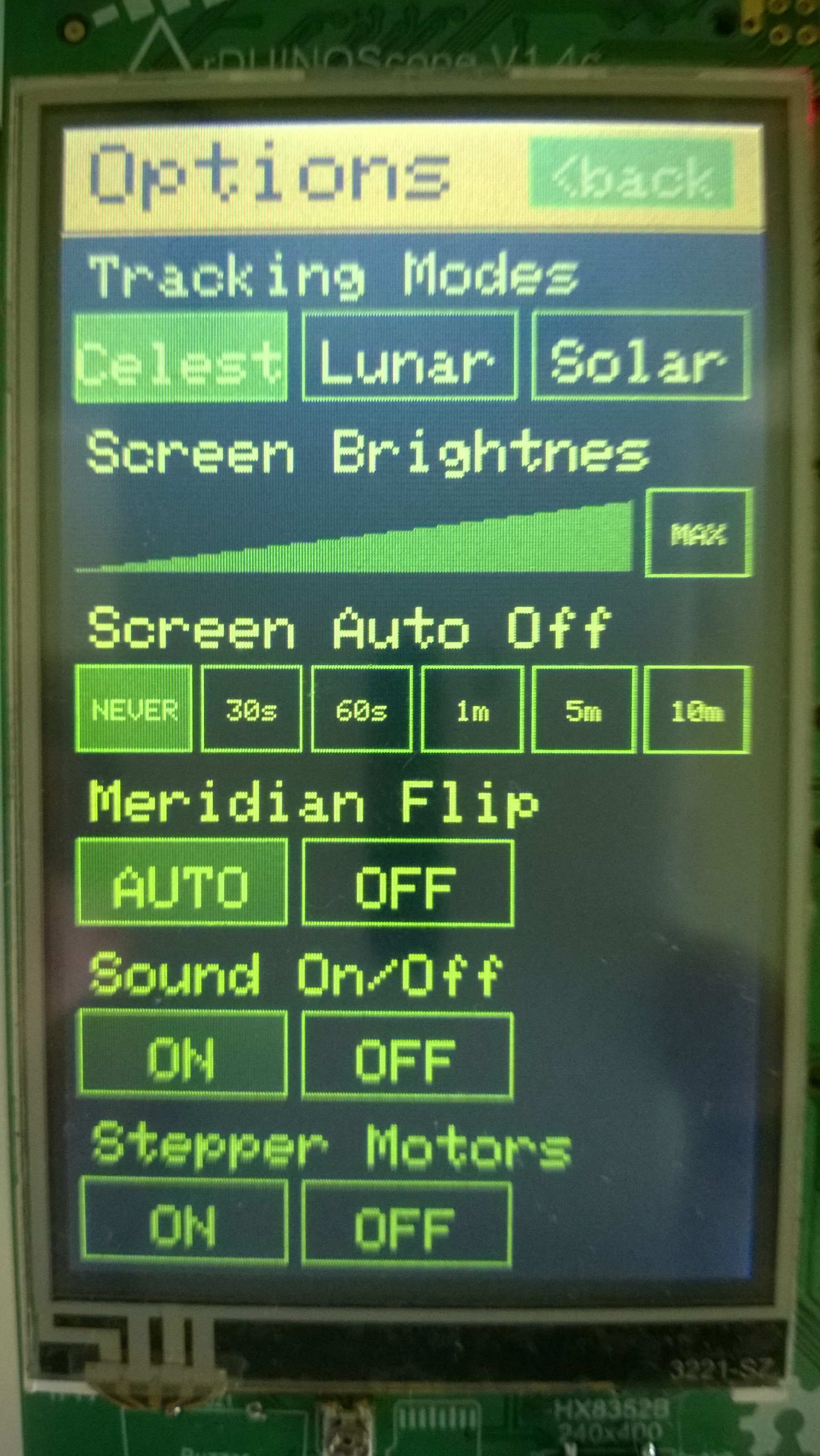
Functionality:
What's inside the rDUINO SCOPE
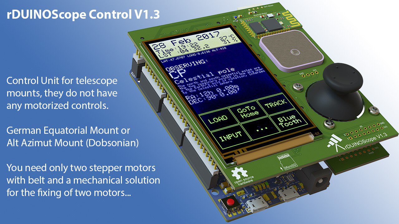
Because this is an Open Source project, Otto Winter redesigned the HW part and come up with his own professional version: https://hackaday.io/project/21397-rduinoscope-control-v13
The challenge the project addresses:
Every amateur astronomer knows the trouble of finding an object to observe, when starting in the hobby. It is the steep learning curve that one needs to overcome, that makes most people give up after few unsuccessful tries. To overcome this roadblock, telescope manufacturers come up with idea to computerize a telescope and make it GOTO telescope. One simply pushes a button ....and voila – The Great Orion Nebula is in the eyepiece!
Those computerized (GOTO) telescopes unfortunately are proprietary and are quite expensive on top of the Euro/Dollar you already spent for your tube and optics. You can’t simply buy the cheapest GOTO and put it on your mount, as they are specific for each telescope. Maybe you aquired an old mount and find out that it is no longer supported for a GOTO ... or that existing GOTOs keeps their high prices!
If you however decide to buy a new shiny GOTO Telescope, you will be amazed to discover that most of them are old looking, feature phone like handhelds, and most importantly all the goodies are sold separately like:
- No graphical screens or touch screens;
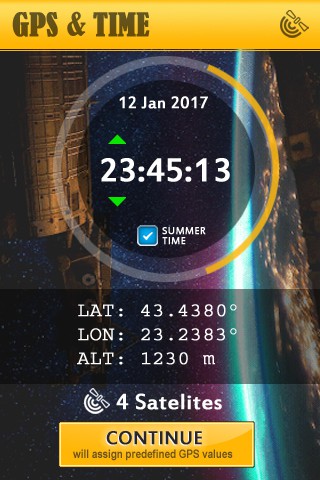
- GPS sold separately or enter the coordinates manually;
- Connection to PC or Bluetooth devices are sold separately;
- To use your smartphone application you need to buy additional hardware;
- Not possible to share your observations with your favorite social media,
- …. And many more restrictions simply not acceptable for the amount you pay!
That’s why I decided to create rDUINOScope, a computerized telescope GOTO controller system, which fits every telescope mount.
It is an Open Source Software and Hardware, which means it is free. I wanted it to be even better than what you can buy on the market, so I have implemented...
Read more »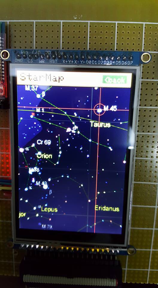


 Hpsaturn
 H00GiE
 zen
zen
 Pavel Zhovner
can i use it on alt az mount