 kevinjkrieger
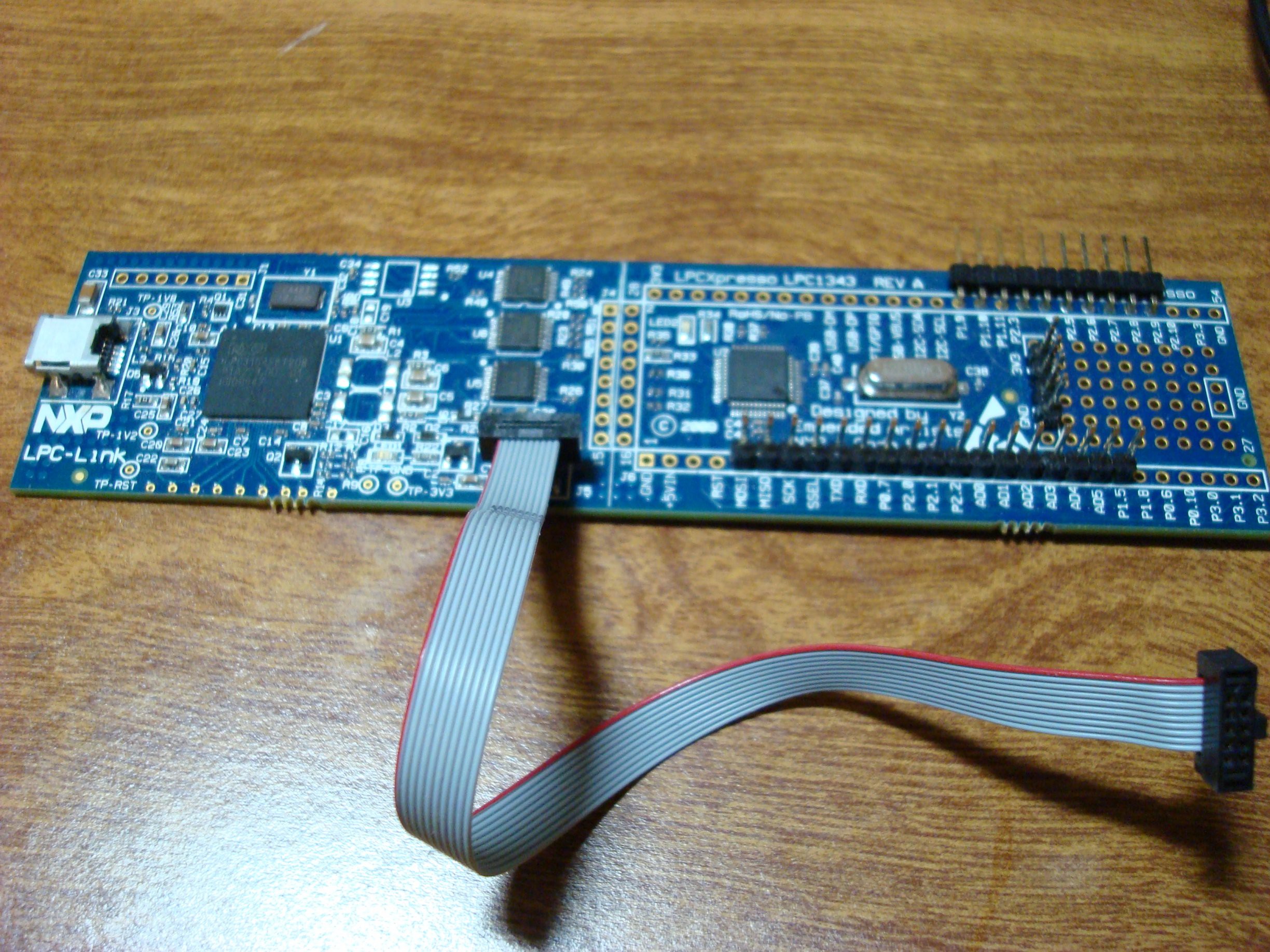
Brain: I needed something capable but not overkill, and I needed to be able to hand solder it. I had an old LPC1343 LPCXpresso board from a school project - so I thought to check on the LPC line of microcontrollers. Sure enough they have several with CAN bus options! The LPC11C14 is simple and has CAN circuitry built-in.
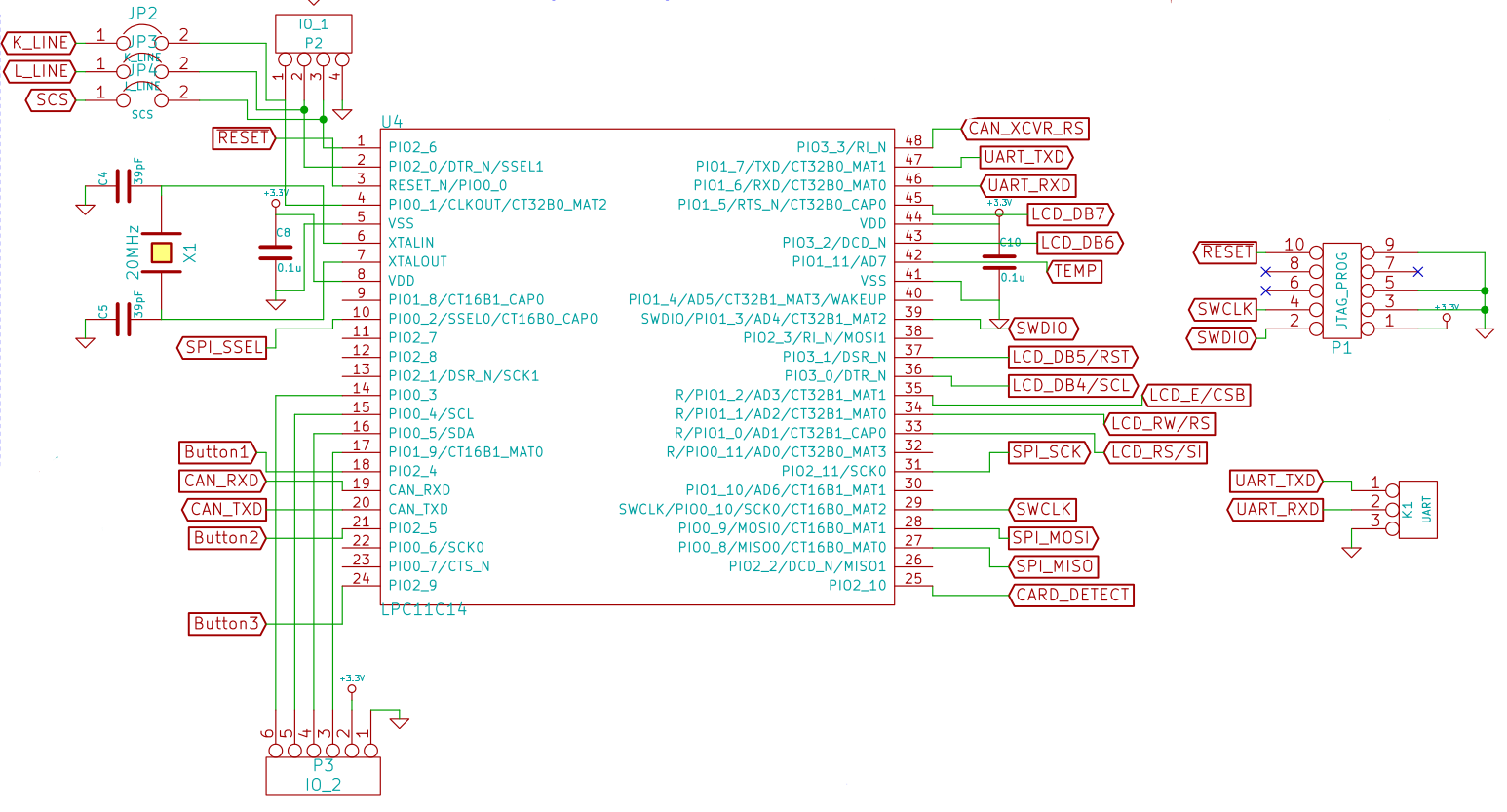
Here we can see the connections that the LPC11C14 has, including the programming/debugging header that attaches to the LPC-Link board. I broke out the UART pins because you never know if you'll need them.
Read more »
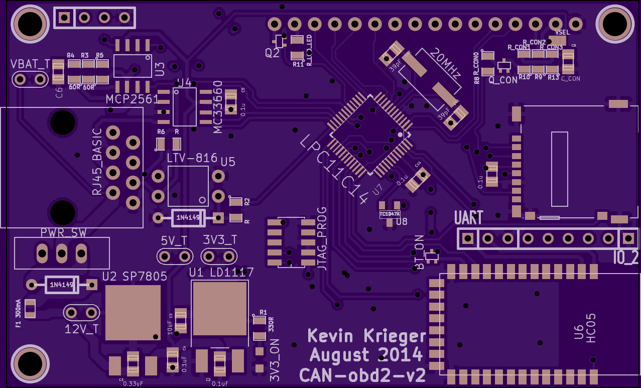 Oh baby.
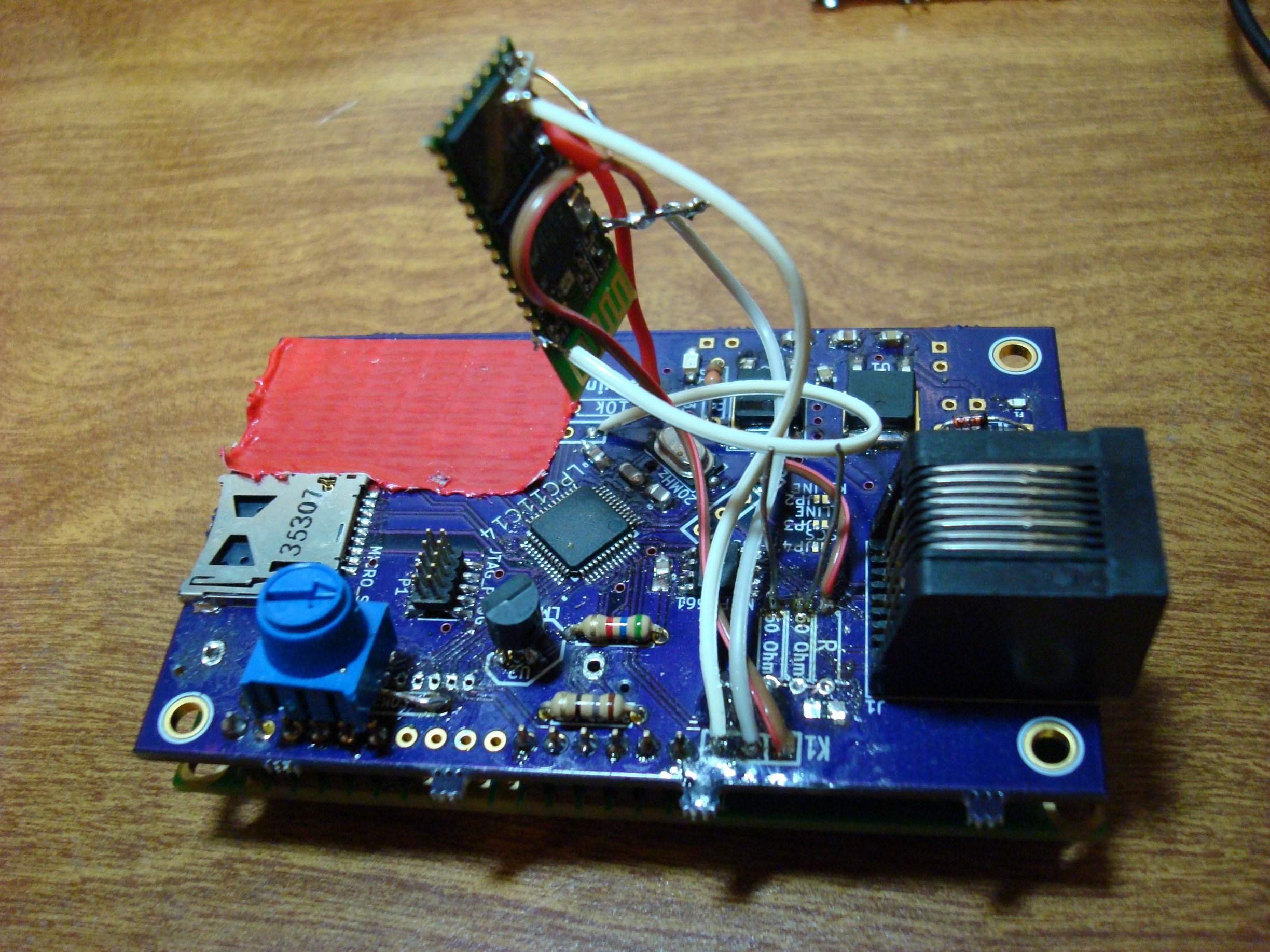
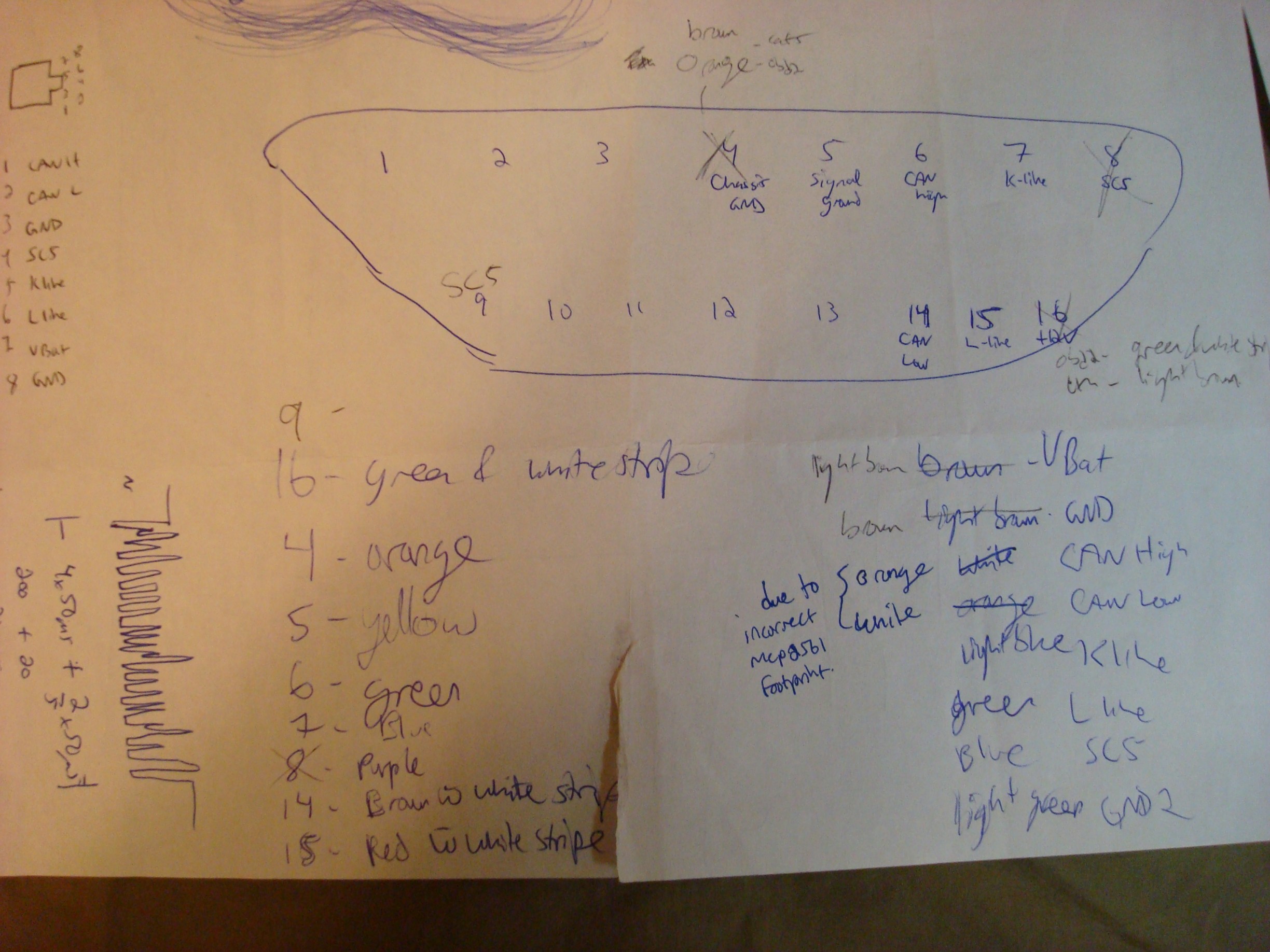 My page that shows just how stupid/colourblind I was. Light brown (GND) and brown (Unswitched lead-acid battery) look the same in my basement dungeon I guess. This is the cause of the short and subsequent frying of 10A worth of automotive fuse.
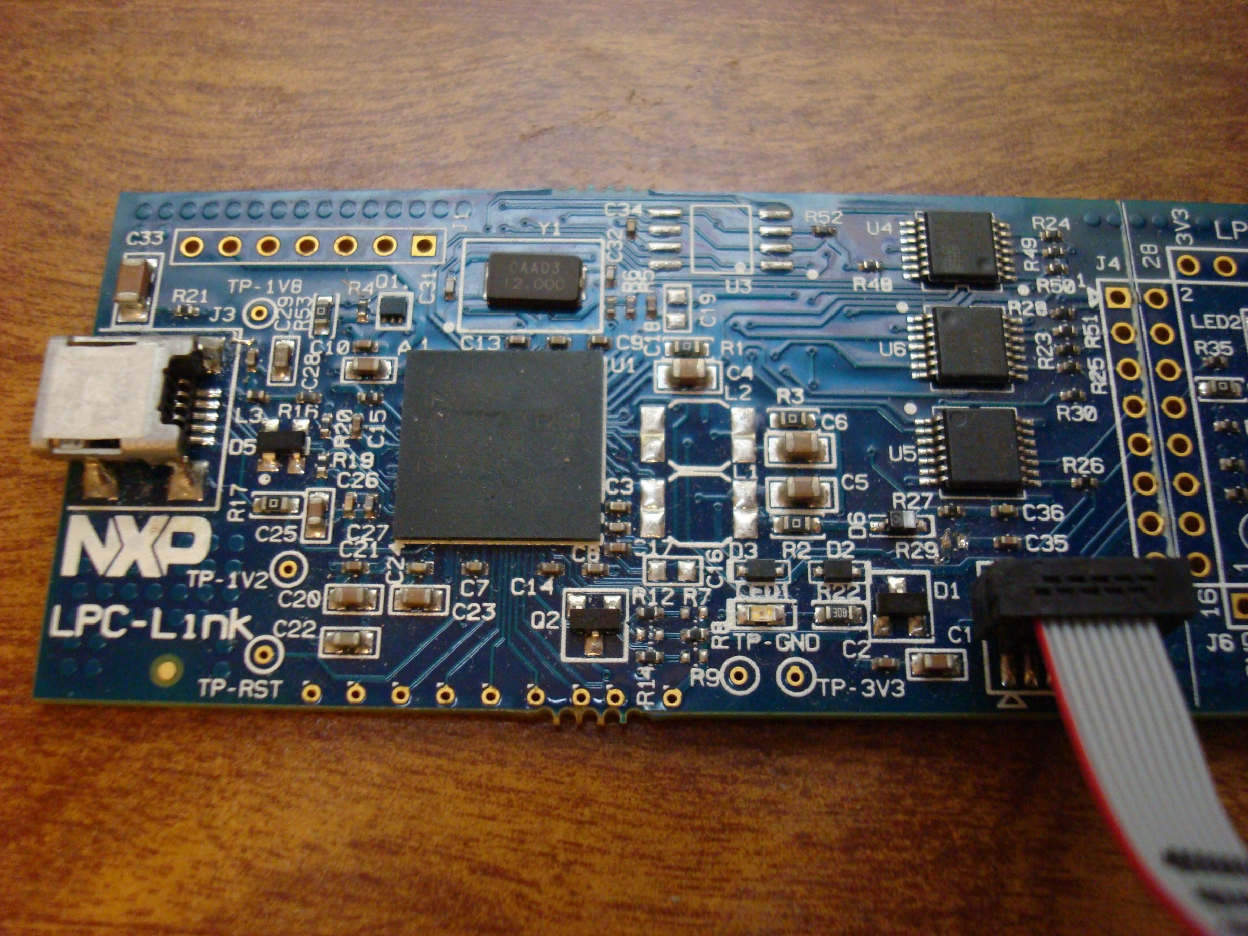 (R29 is just to the left upper corner of the connector).
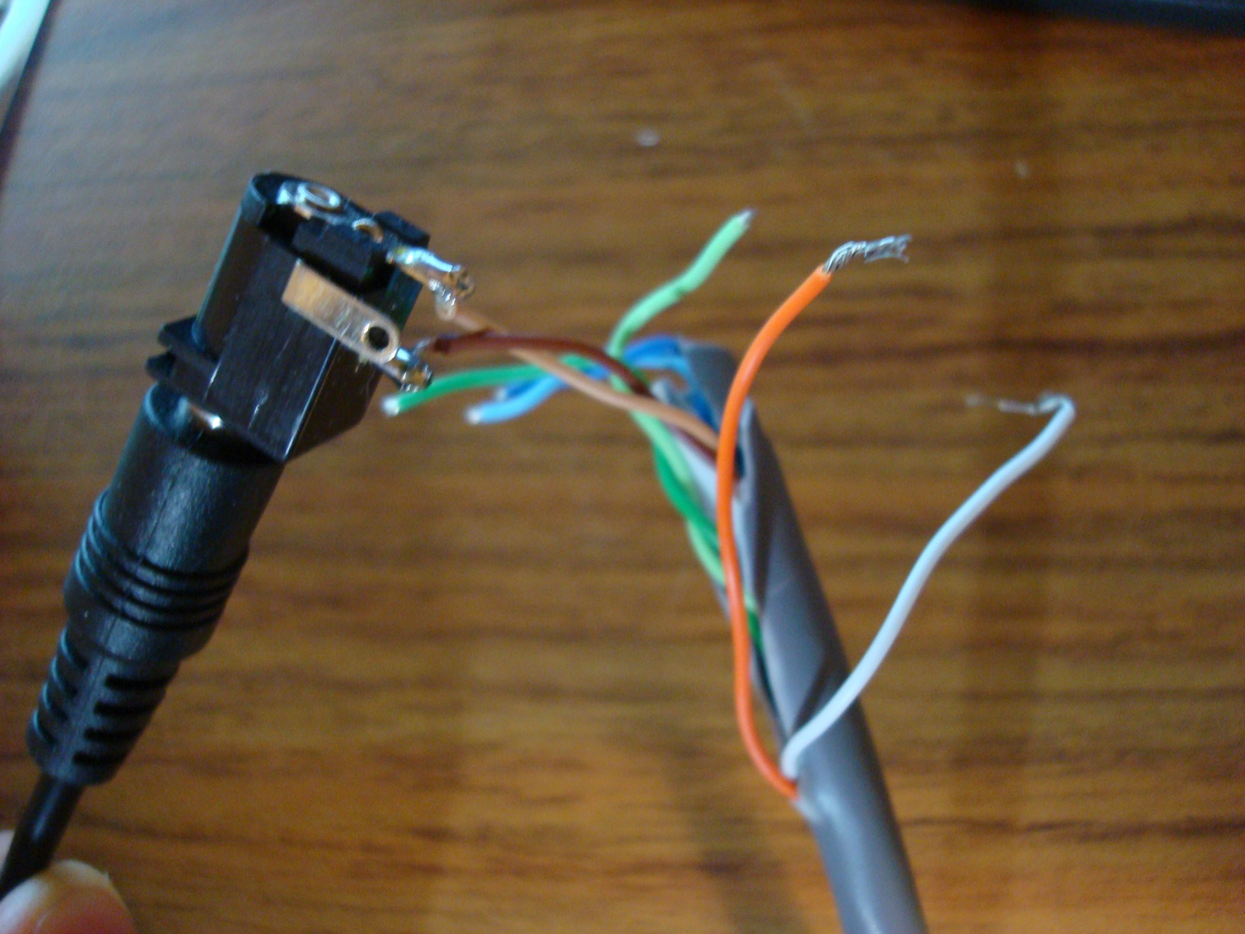
 Dimitar
 Kevin Santo Cappuccio
 charliex
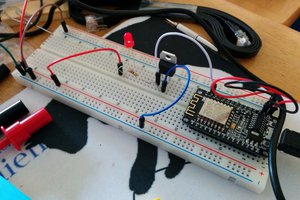
 WJCarpenter