 kevinjkrieger
Well that was a bit of a hassle. I followed the instructions here though: http://www.lpcware.com/content/project/lpcopen-platform-nxp-lpc-microcontrollers/lpcopen-v200-quickstart-guides/lpcopen-1
Also, in order to power the board via the LPC-Link, you need to have the resistor R29 populated (solder jumper it!). It supplies 3.3V, so the temperature sensor won't work, and neither will the CAN transceiver or +5V LCDs, but at least you can program the thing. Check It: http://www.embeddedartists.com/sites/default/files/docs/schematics/LPCXpressoLPC1343revA.pdf on page 4/5 you'll see the text "J5 can connect to external JTAG interface if LPCXpresso targe side (LPC1343) is disconnected." So you just cut the traces like in the photo here:
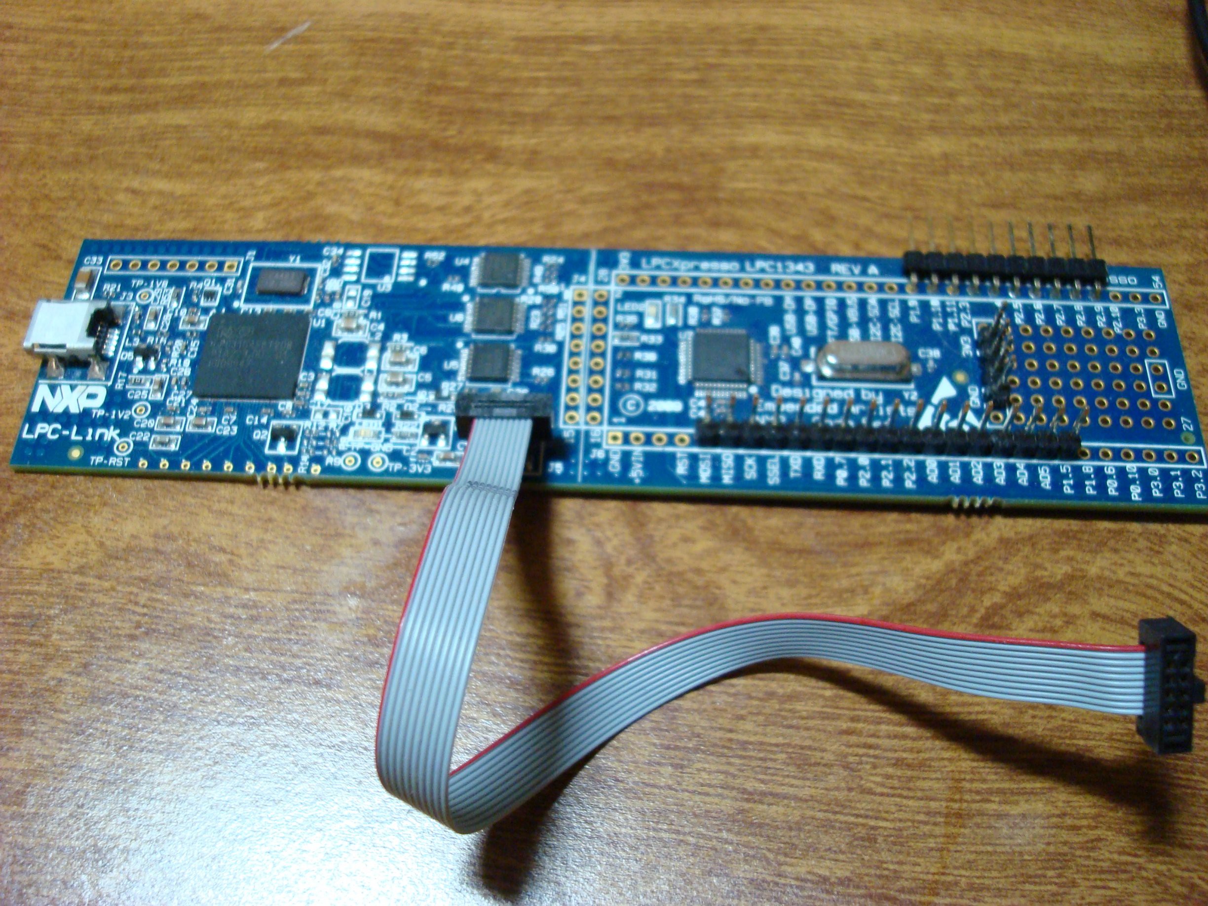
And you can populate the jumper that you see unpopulated here:
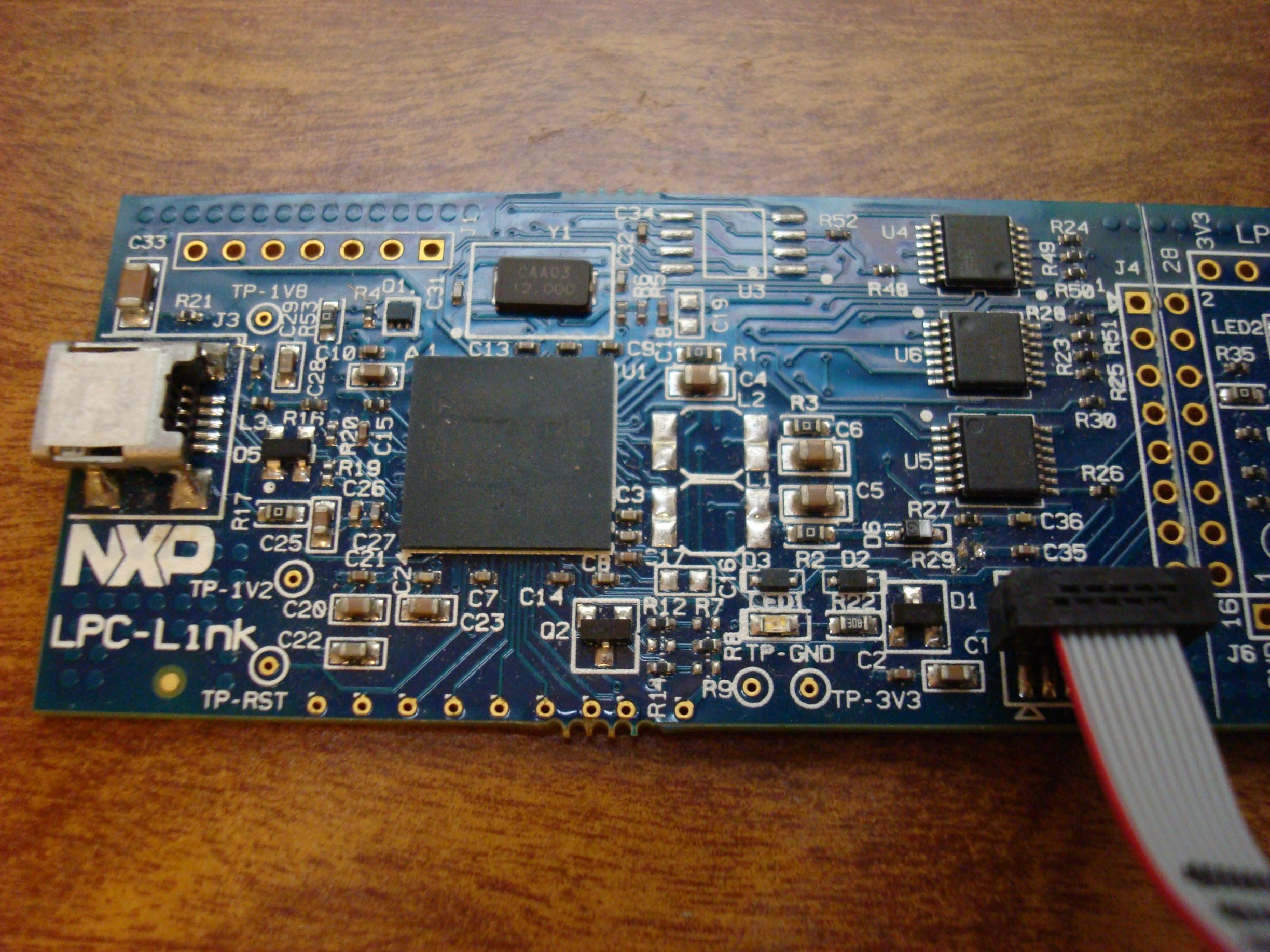 (R29 is just to the left upper corner of the connector).
It worked! I just modified the example blinky project to output a square wave on one of my broken out headers. I did find out that a couple of the pins on that header are open-drain... That always gets me.
Discussions
Become a Hackaday.io Member
Create an account to leave a comment. Already have an account? Log In.