MagicWolfi
-
1st response
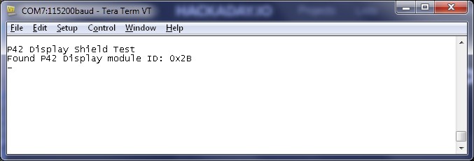
07/26/2017 at 00:43 • 0 commentsAfter some typing, compiling and syntax error fixing, this was the 1st response of the video chip on the shield:
![]()
Initially I was scratching my head about what was going on, because page 24 of the datasheet says, the default value for the ID register is ABh, but page 49 tells the correct value of 2Bh and everything is hunky-dory.
Now comes the easy part of figuring out how to configure the video display controller. The first image will be amazing as my only device with video input is a 40" TV.
-
2 Prototypes
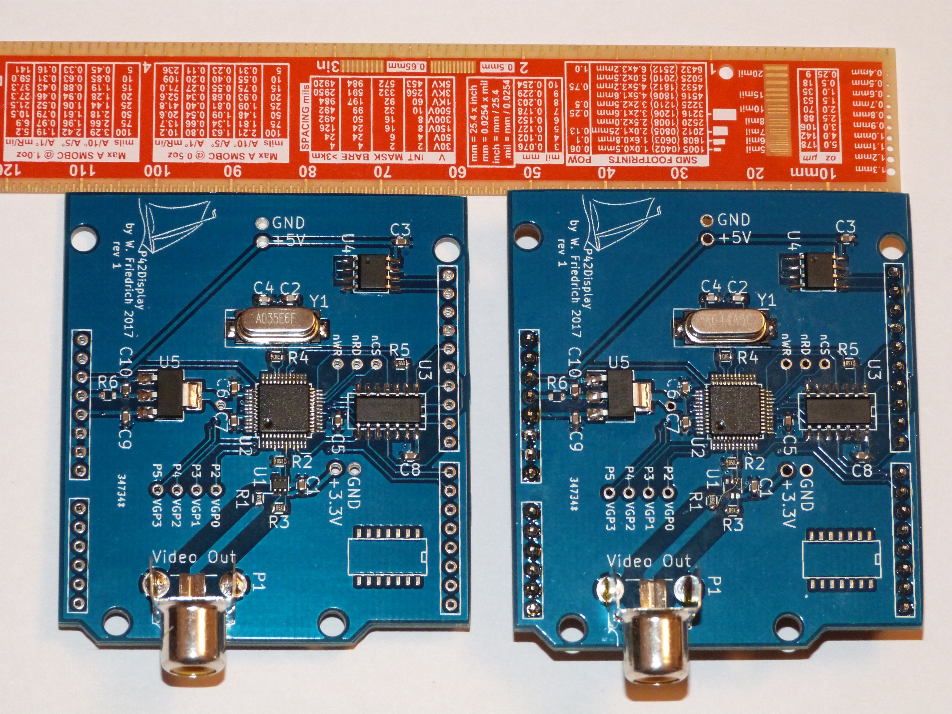
07/23/2017 at 02:18 • 0 comments2 boards are populated with all components (except the Arduino headers on one of them). One is build up with PAL crystal, the other with a NTSC version. Also only the PAL version has the additional video driver installed, it is just bridged on the other board. Initial test showed the 3.3V power rail OK and no smoke got released.
Things to note:
- The KiCAD Arduino shield footprint has connector through holes that are very small for regular pin headers. I almost got a press-fit connection. The extra long female headers have thinner pins and are OK.
- All other footprints that I grabbed from the KiCAD libraries turned out to be correct (maybe I was just lucky ;)
- Testpoints are very helpful.
- I like silkscreen that is large enough to read without microscope.
Now the programming begins, SPI communication first and then configuration of the video output. Then the fun starts with image display functions and porting Doom.
![]()
-
PCBs are in
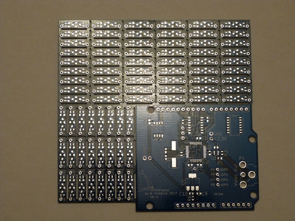
05/28/2017 at 01:50 • 0 commentsFinally the bare PCBs arrived from DirtyPCBs today. This time it took the full 8 weeks, which is OK. That is what they say with the slow shipping order. The quality is very good as usual. They even managed to put a solder dam between the pads of the 0.5mm QFP footprint. This will make hand soldering super simple. And they do panels if you put multiple designs on the board by yourself. They do nice thin slots and next time I will try mousebites for even easier separation. Now I am off to the soldering iron.
![]()
The little board is an in-line current source (* 78), which will be documented in its own Hackaday.io project.
-
Todo list
05/07/2017 at 16:51 • 0 commentsAs the project page does not have a Todo list feature, I will try to "re-use" a project log for this. Starting now and editing later:
- Add 3D models for missing components in KiCAD design (RCA conn, SOT23-6 opamp,HC49 crystal)
Rev 02:
- DONE Add SPI flash (2Mbit, SO-8, 25x20 type)
- DISMISSED Add some LEDs (power rails, monitor detect, SPI activity)
- A̶d̶d̶ ̶b̶u̶t̶t̶o̶n̶ ̶o̶r̶ ̶j̶u̶m̶p̶e̶r̶ ̶t̶o̶ ̶e̶n̶a̶b̶l̶e̶ ̶t̶e̶s̶t̶ ̶m̶o̶d̶e̶ testpin is for factory test only :(
- DONE Add pull-up resistors on signals nWP_5V, nHOLD_5V
- DONE Disconnect signal Testmode(_5V), it is for factory testing only
- DONE Add in-line resistors on signals nWP_5V, nHOLD_5V on the 'left side' of the pull-up/downs.
- DONE Use 22R - TVS - 22R instead of 75R output impedance matching resistor. TVS type: CG0603MLA-5.5ME
- DONE with 74LVC4245A Replace 74LVX50 with TXS0102 / TXB0106 / 74LVC4245A / SN74LVC1T45 for availability.
- Add monitor detect line.
-
Virtual debuging
04/17/2017 at 02:12 • 0 commentsIf you look at things long enough, mistakes get noticed. I just updated the schematic with a 512Mbit EEPROM (not a bug) and replaced the 74LVC07 driver with a 74LVX50. The LVC07 would have the 5V tolerant inputs for the signal from Arduino to the video chip which I was looking for, but is an open-drain driver which does not really help with SPI signals. So I replaced it with the 74LVX50 which has the same package and pinout. Easy fix when the parts are not ordered yet.
NTSC/PAL Video Display Shield
An Arduino NTSC/PAL video display shield with integrated framebuffer and composite video output.