0%
0%
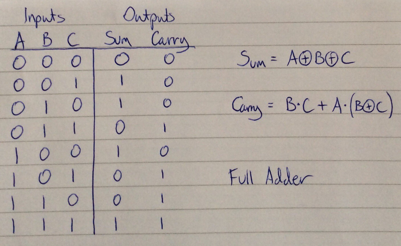
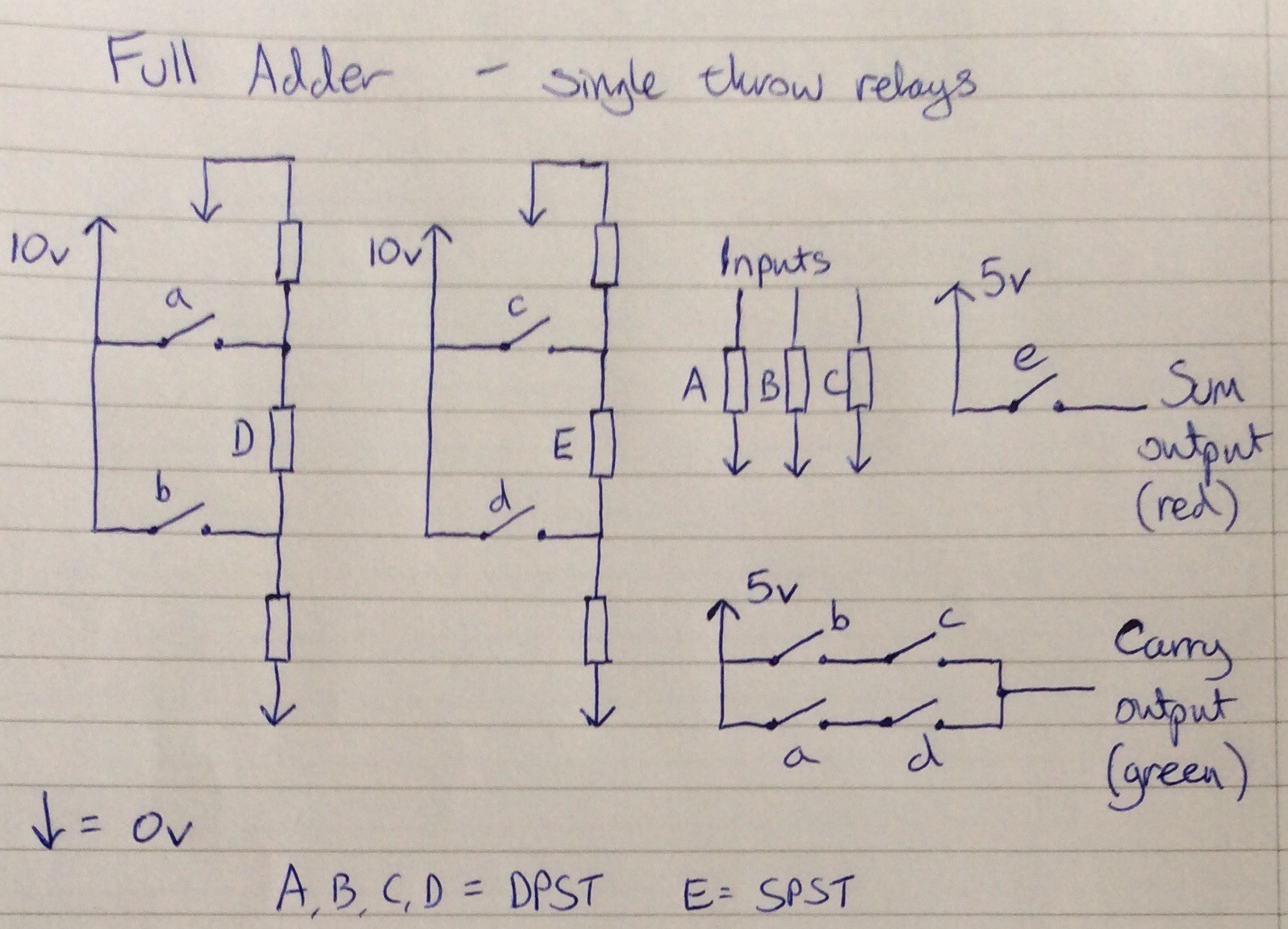
Single throw relay computing
Ideas about using single throw relays for computing, and working prototype circuits.
 will.stevens
Become a Hackaday.io member
Already have an account? Log in.
Just one more thing
To make the experience fit your profile, pick a username and tell us what interests you.
Pick an awesome username
hackaday.io/
Your profile's URL: hackaday.io/username. Max 25 alphanumeric characters.
Pick a few interests
Projects that share your interests
People that share your interests


 Dr. Cockroach
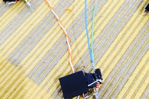
 GNbyma
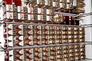
 matseng
Reed relays exist also in dual throw, moreover I think they might be done from cheap reed switches (e.g. https://it.aliexpress.com/item/32947287626.html?spm=a2g0o.cart.0.0.1fb73c009qLgQj&mp=1) with some wire rounding...