 will.stevens
This video shows a full adder made using 4 DPST reed relays and 1 SPST reed relay. All combinations of inputs are cycled through.
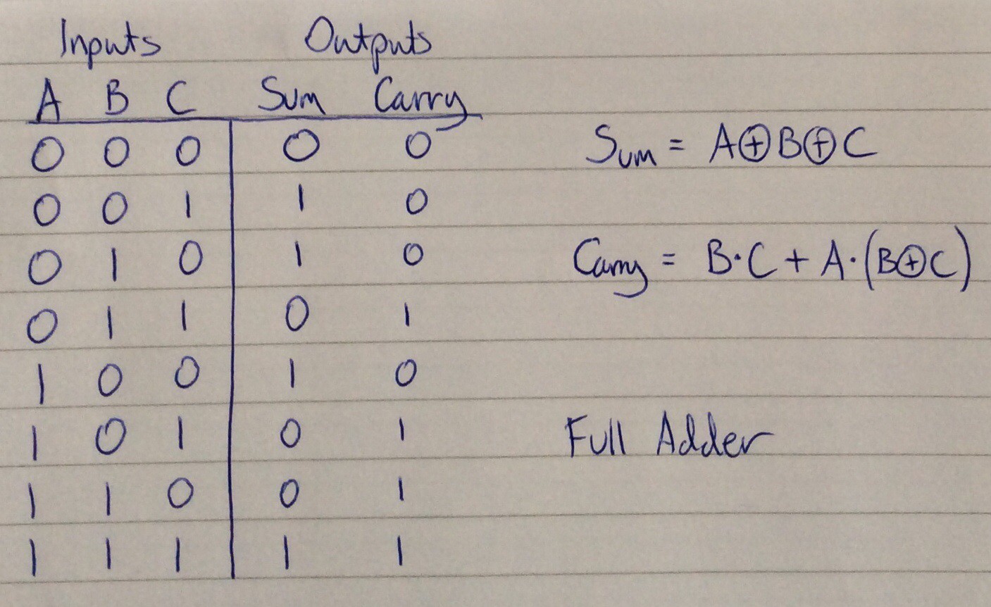
Below is a truth table and the circuit diagram followed by an explanation [explanation added following discussion in comments]:
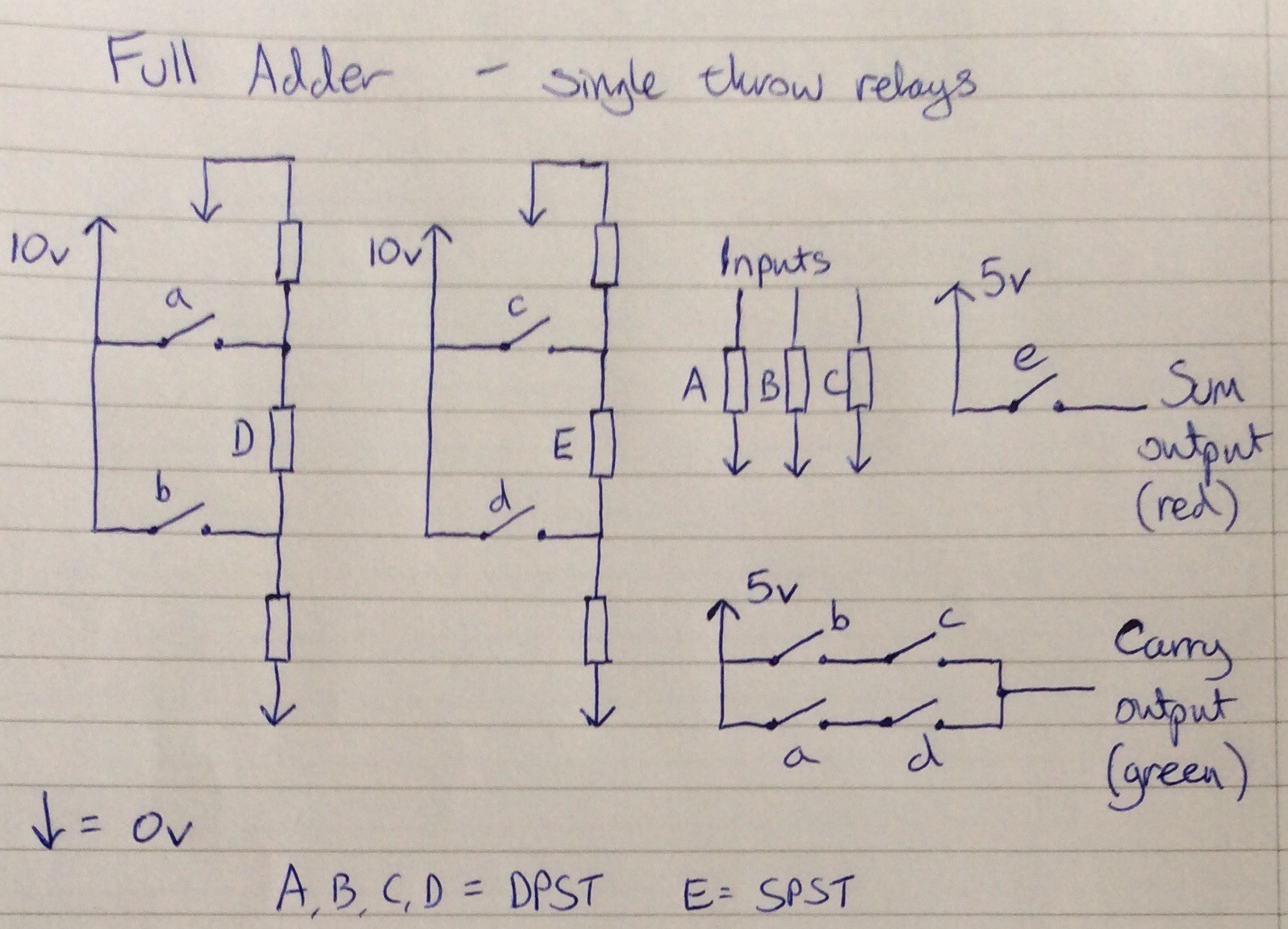
The rectangles labelled with upper case letters represent relay coils. The corresponding contacts are represented using lower case letters. The unlabelled rectangles represent resistors, where the resistance is equal to the resistance of a relay coil. All of the relays used have a coil activation voltage of 5V.
All inputs and outputs use the same convention to represent binary digits 1 and 0: 5V represents 1, and no connection represents 0.
D and E are used to implement XOR gates. Relay coil D will activate if either a is closed, or b is closed, but not if both are closed. Similarly coil E will activate if either c is closed or d is closed but not both. Contact e can therefore be used to obtain a XOR b XOR c, i.e. the sum of the inputs.
Because relays A, B, C and D are double pole, the second set of contacts in each can be used to implement the carry function - the ladder arrangement in the bottom right of the circuit diagram.
Discussions
Become a Hackaday.io Member
Create an account to leave a comment. Already have an account? Log In.
Thanks for posting this.
The carry is wrong when ABC = 100. In this case the "a" contact will be
closed and the D relay will be powered thus closing the "d" contact and
making the carry output a 1 when it should be 0. The problem is easily
fixed by swapping the "a" and "c" contacts in the carry output circuit.
The problem is traced back to the equation Carry = BC + A(B^C). [^ =
xor]. B^C is not available in the circuit. But Carry = AB + CD = AB +
C(A^B).
As has happened with other folks, a friend gave me a couple hundered
relays with the hope they could be assembled into something interesting.
They're unused reed relays with SPDT contacts. Your use of resistors is
much better than my idea of using bias magnets to form some normally
closed contacts.
Are you sure? yes | no
Hi !
Your diagram is not clear because the same symbol represents both a resistor and a coil.
The coils and the contacts are separated and are not easy to logically associate.
I am never sure I really understand what the diagram represents...
I hope this helps though :-)
Are you sure? yes | no
Nice keyboard by the way ;-)
Are you sure? yes | no
thanks, I see what you mean about the coil and resistor symbols - I forgot to put an R next to the resistors on this diagram. The resistors are the ones without labels. I'll edit the log entry later and add an explanation for the circuit. I got the idea for drawing the circuits like this from a 1960s book about relay circuits, where a capital letter represents a coil and lower case letters represent contacts.
Are you sure? yes | no
This also shows the evolution of technical drawings :-) I have some difficulty reading old diagrams...
Anyway I avoid separating/splitting a part because the logic function is harder to understand.
Good luck :-)
Are you sure? yes | no