 patchartrand
The servo project has started in 2015 when I decided to build a robot arm. First and foremost is to find a drive system that is at the very least as strong as a human arm (I used my arm as a benchmark). After looking under every internet rock it seems like there is no real product that can do this under 3000$. There are some servos that do come close but there is no way to extract any information from them. Ex: Position, speed, torque applied etc....
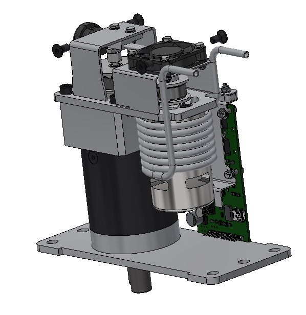
All these problems ultimately made me want to make my own high powered servo. My benchmark for a servo will be as follows:
- 60 lbs*ft at stall
- 60 rpm free rotational speed
- Absolute positioning
- Programmed output angle range
- Arduino Based micro controller
- 30A continuous motor controller
- Current sensing
- On board temperature sensing
- Brushed DC motor
- Most compact design possible
- water cooled as option (Would increase the overall power rating by 15%-20%)
This servo will not be super duper accurate down to the 15 arc-min. This is meant to be used by the hobbyist, prototype validation or robotics that do not need accurate positioning (like prosthetic, remote control lawn mowers, remote control cars etc.). This limitation is due to the absolute positioning sensor (resolution of 0.1 degrees). When the servo is done, if someone wants to put incremental sensors onto the motor output shaft then I would think that an accuracy of 20 arc-min is achievable (limited by the backlash of the gearbox) .
I think that this servo will be an essential building block for any projects that want to interact with human scale objects or systems. Without this (relatively) inexpensive servo, it will greatly reduce the development time of large project. This will liberate some precious time to give the inventor to focus onto the larger problem that he/she it trying to solve. I think that many inventor and entrepreneurs are simply overwhelmed by the complexity of human scale projects because they will have to design E.V.E.R.Y.T.H.I.N.G. from scratch. These "Lego" pieces will help to alleviate the development process.
As of now, I have done the following:
- Tested 3 types of gearboxes to measure efficiency at high torques (planetary is king)
- Built Prototypes with worm gearbox(nmvr 40), bane bot gearbox and CNC planetary (PLE60)
- Programmed PID Loop, then added in a velocity error signal to tame overshoot. Now a PIV loop
- Sized all components: Motor, Gearbox, timing belt, timing pulleys, FET, shunt resistor and mounting hardware
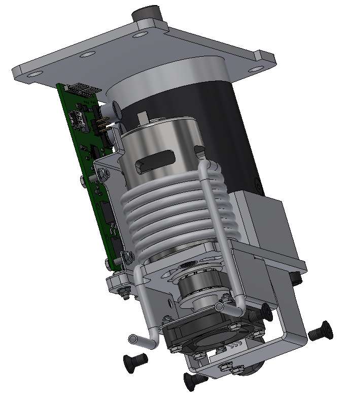
- Cad all parts and completed 80% of the design
What is left to do:
- Finish the ESC design
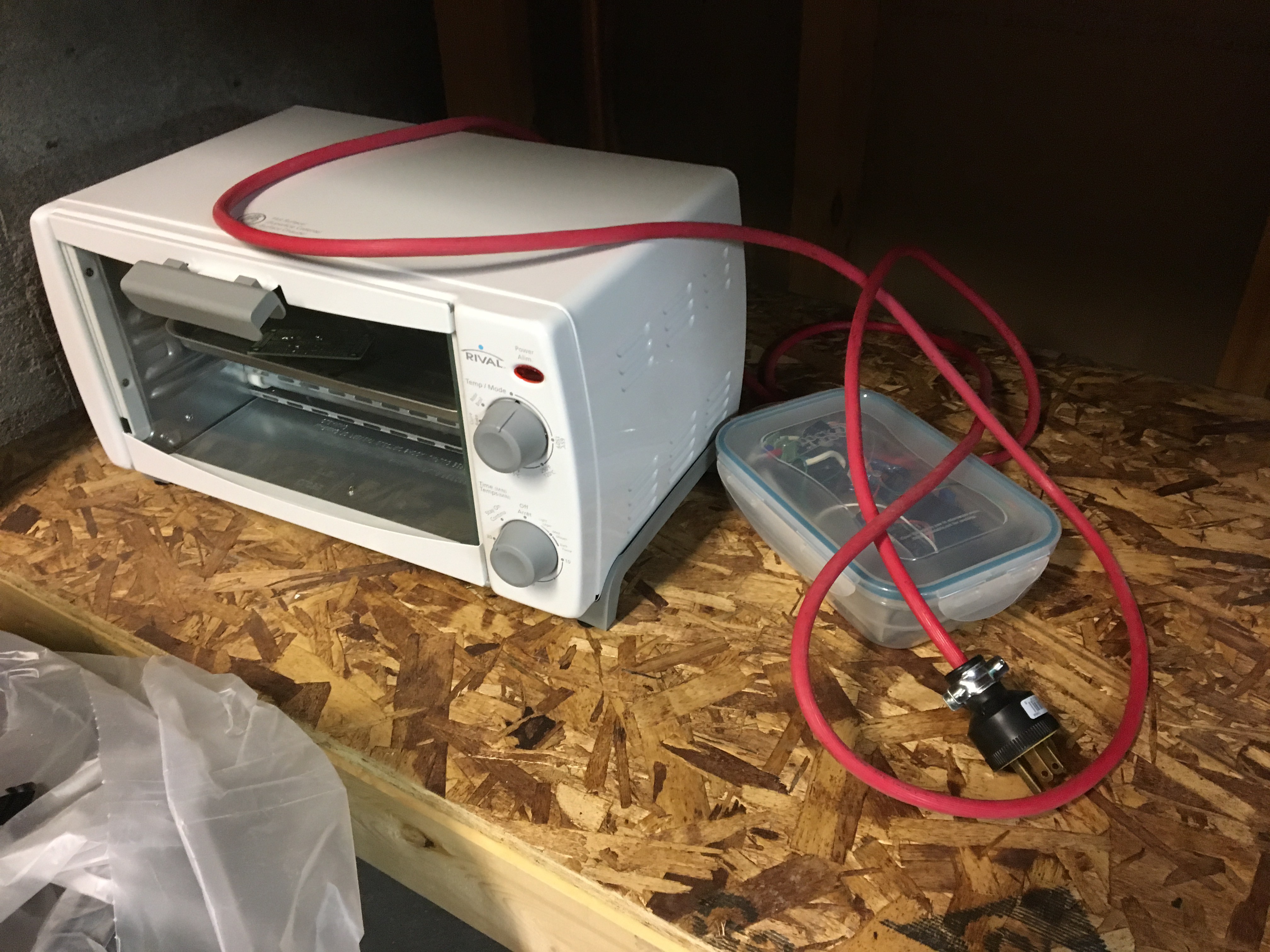
- Build ESC board
- Program in the motor controller
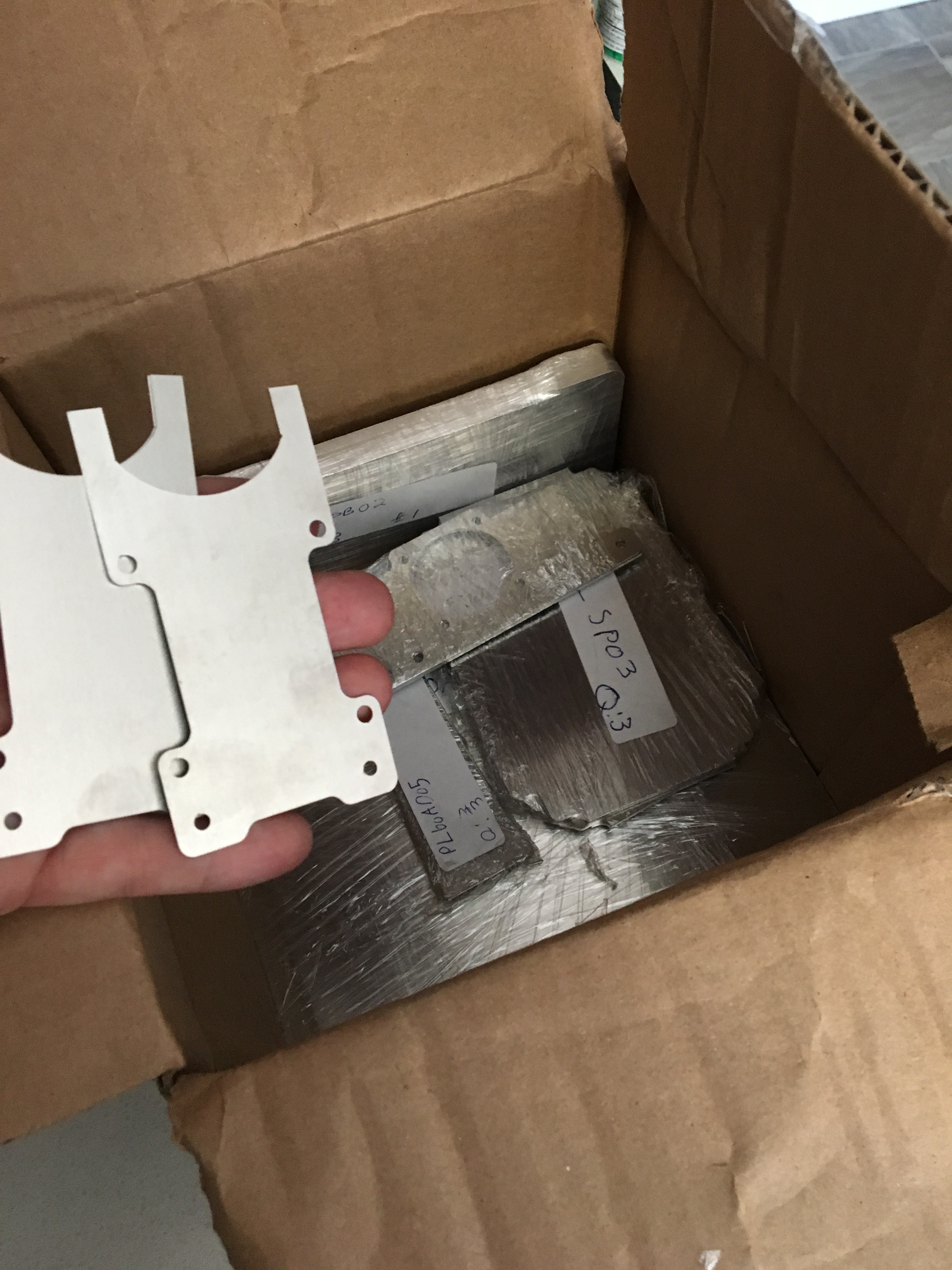
- Order all aluminum parts to be laser cut
- Order remaining parts
- Bend aluminum parts
- Weld the main body of the servo to mounting plates
- Final assembly
- Lots and lots of testing
Once the 2nd prototype is completed I will compile the parts list and see where I sand for a price point. As of right now I am aiming at 750usd per unit.
Licenses:
- Circuit Maker (open source)
- Arduino Development platform (open source)
- Autodesk Inventor (Yearly subscription)
Below is a link to all of my shared files on the projects so as the project moves along, the information will become more and more complete.
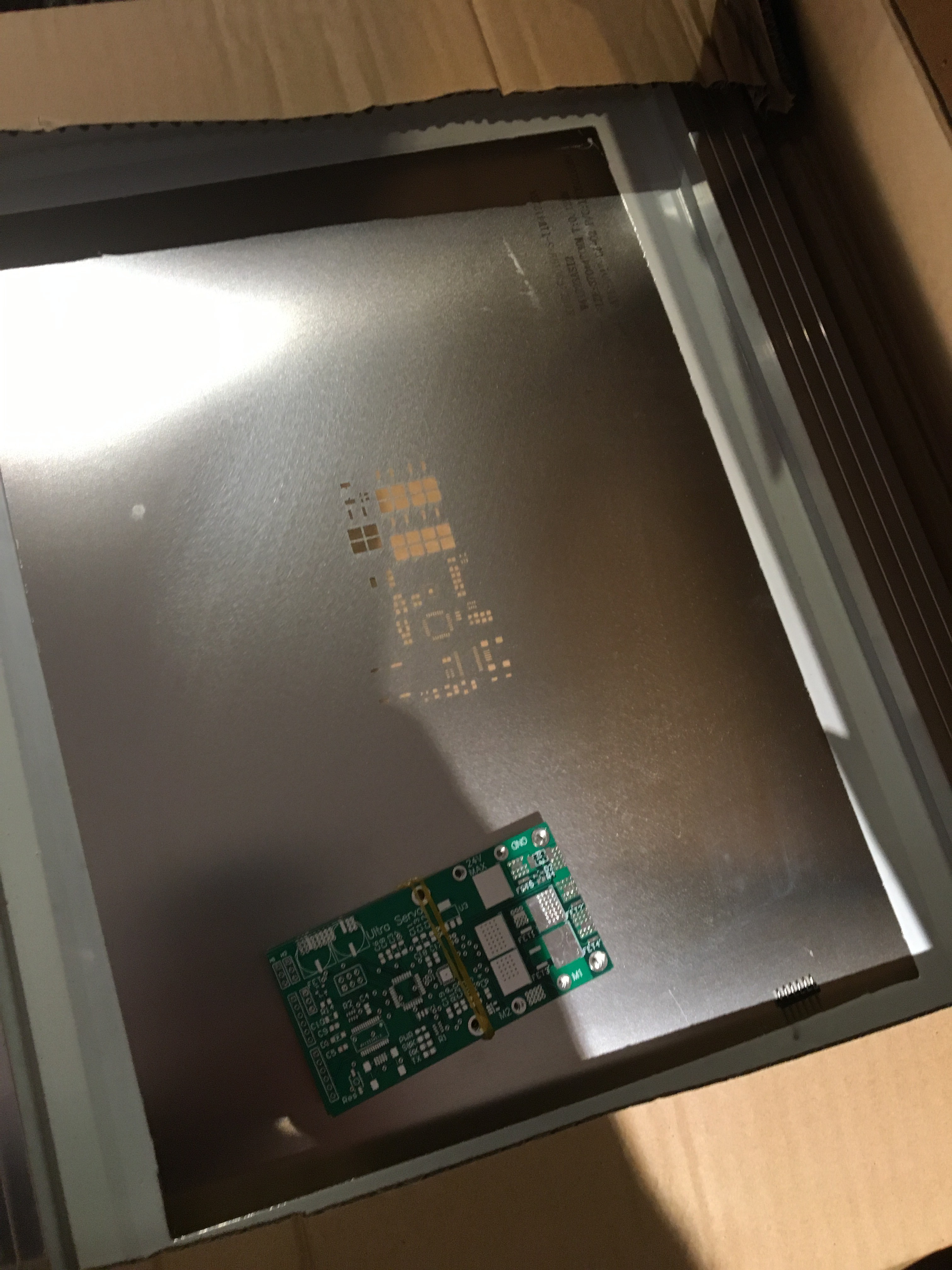
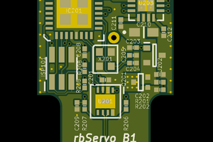
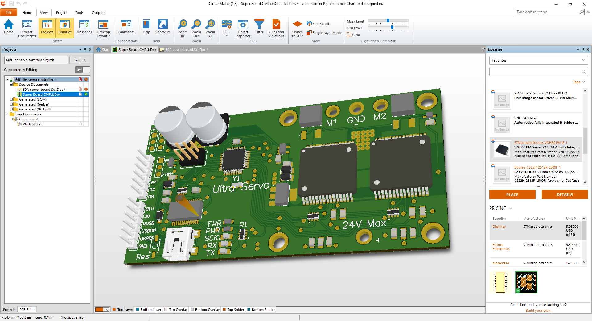 AAAANNNNDDDD just before I sent the gerber files to the board company.... I find out that If i double up the VNH5019A-E chips, they cannot use the current sense. SO, this was quite the setback. So then I was stuck designing the 4X mosfet setup to control a board. I was a little hesitant to control the Mosfets from an Atmel chip directly (with the gate drivers applied). This would be challenging for me and any one what would want to add in some custom code without affecting the motor controller's performance. So I did some research and found the DRV8702QRHBTQ1 from Texas Instruments. This chip takes quite a bit of guesswork out of the design. The integrated shunt resistor amplifier, boost converter gate drivers and on and on... So I put it in my circuit and I am now hoping for the best. Below is a screen shot of the completed board.
 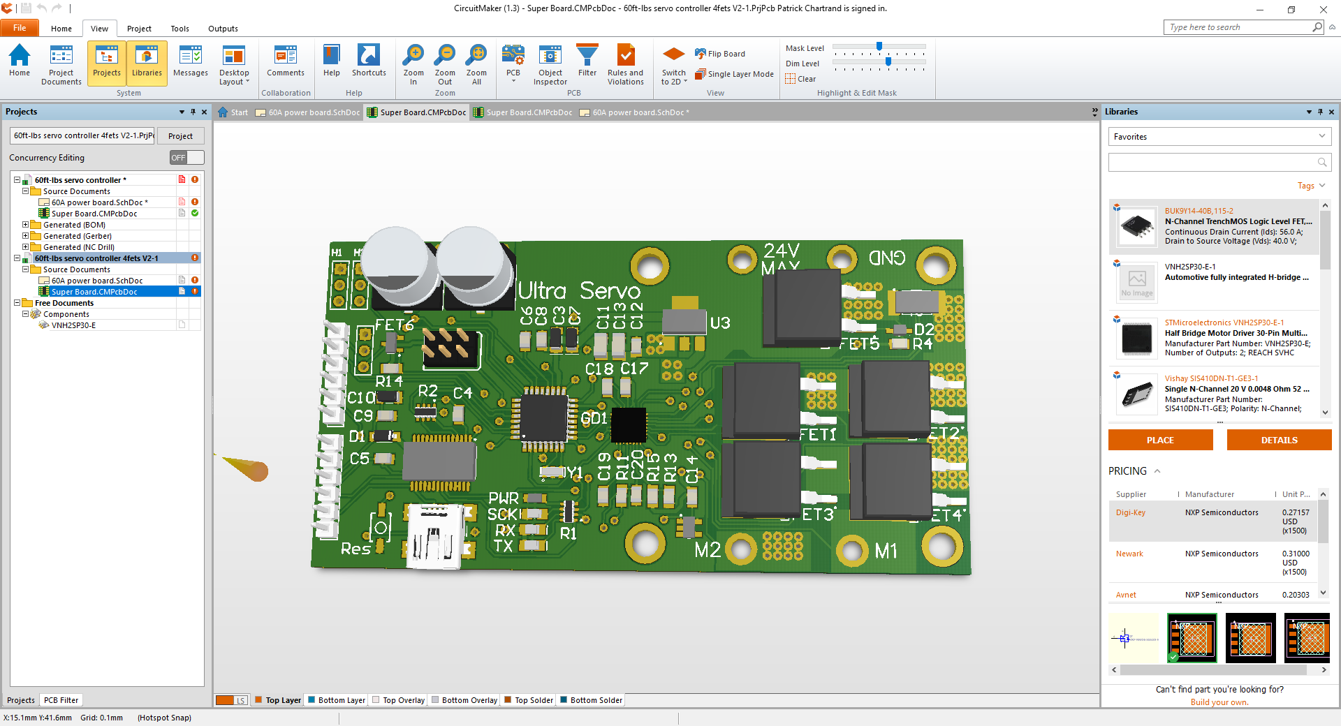 With all of the design criteria met, I sent the Gerber files to the board manufacture and ordered all the components.


 RasmusB
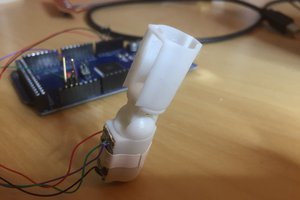
 Tim Wilkinson
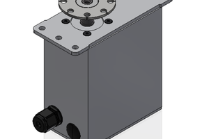
 Martin Vincent Bloedorn
If you are interested in another encoder idea, check this out: http://techref.massmind.org/techref/io/sensor/pos/enc/greycodes.htm
It occurred to me that if you daisy-chained n-bit encoders with 1:n reducers, you could *drastically* increase the resulting resolution. (...with backlash giving slight, yet increasing rounding errors as you go down the chain.) For example, if you had an 8bit encoder that was connected through a 8:1 reducer to a second 8-bit encoder, you'd end up with ~16bits of resolution, which is 0.0055 degrees.
Encoder mask template for Inkscape: http://www.dgkelectronics.com/inkscape-optical-rotary-encoder-disc-generator-added-single-track-gray-encoder-support/
Hope this helps!