 Wassim
If you would like to get support, give feedback or discuss new ideas related to this stm32 project ? It's possible to directly discuss on the forum
https://homesmartmesh.discourse.group/
STM32 RF Node - One HW Many appications
This STM32 RF Node is the main IoT hero of the #Home Smart Mesh project.
- Application Firmware on : IoT_Frameworks
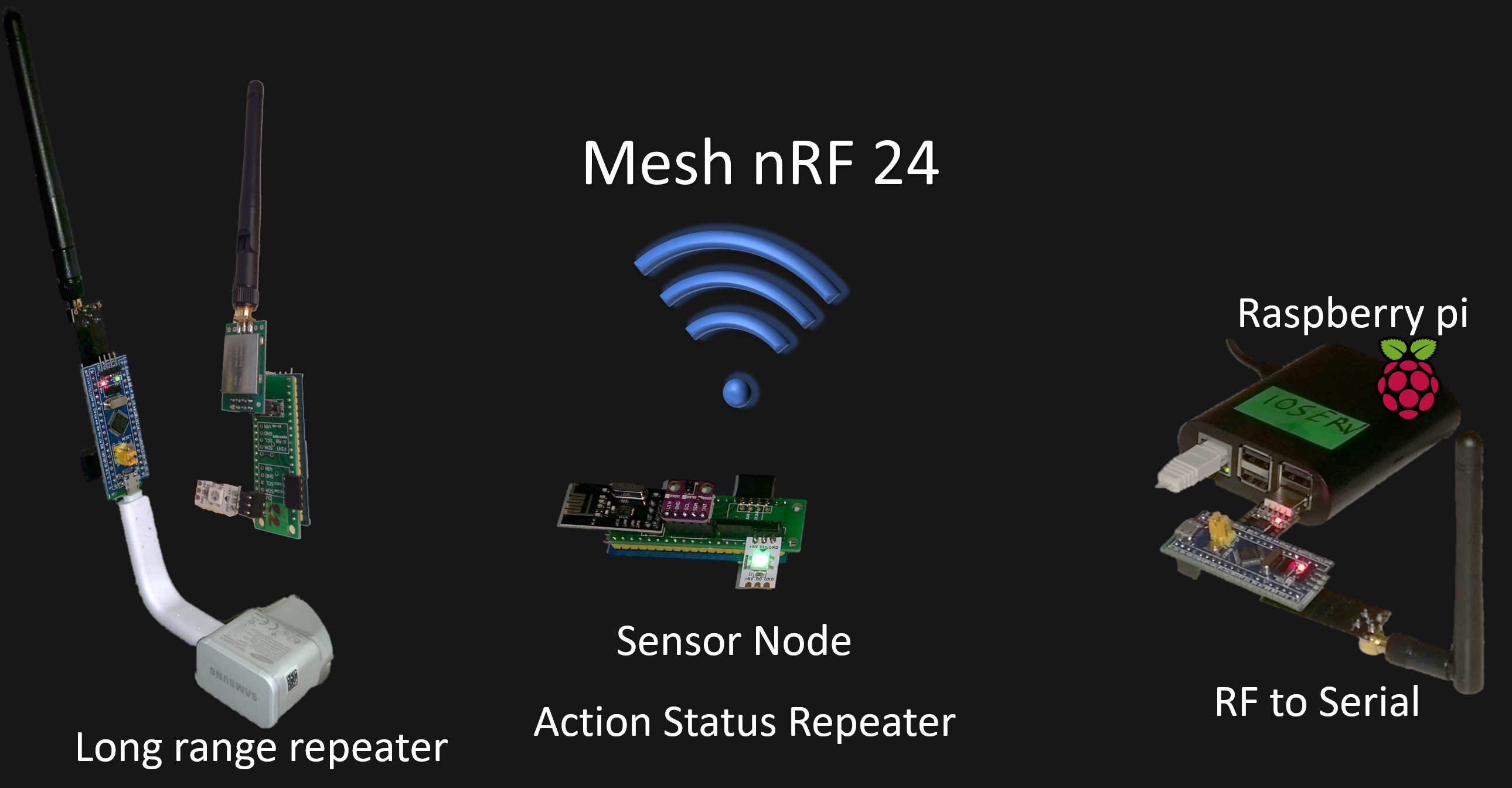
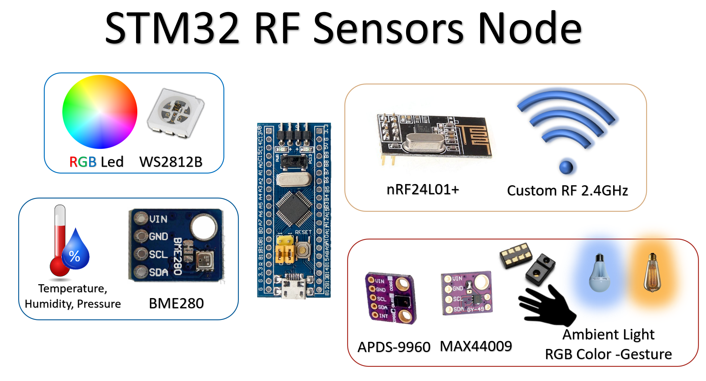
- rf_bridge : Mesh repeater Node with sensors (BME280 + APDS9960)
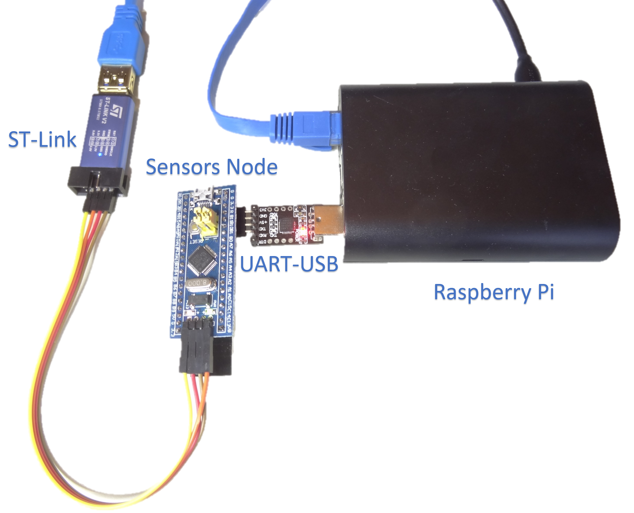
- rf_uart_interface : RF mesh to serial, to be used with the Raspberry pi c++ app.
- host_controller_interface : Open API to control and diagnose the RF mesh with the Raspberry pi Python commands
- action : Fun and game application, RF distributed state machine managing group speach sessions.
PCBs repository
The PCBs design files are shared as open source, free to use without any restriction at github
IoT Boards details
STM32 RF sensors Node Concept
- Always connected to a power supply (no low power worries)
- usage as RF dongle for a Raspberry pi
- RF repeater with color status
- Fixed sensors node (wireless nodes are more efficient but this one is simpler)
- Control node (hopefully when the gesture gets working with the APDS9960)
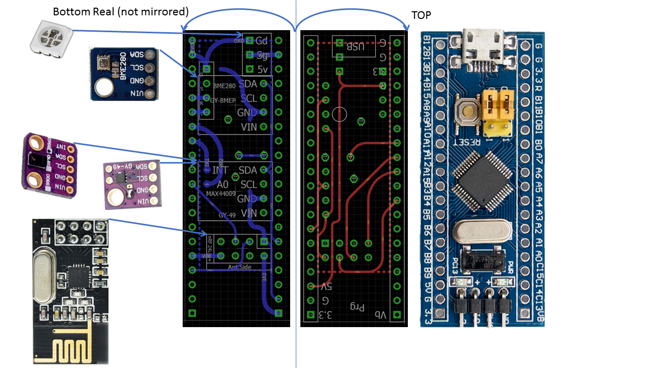
STM32 RF sensors Node PCB v2
- Added USB connector for power supply, although not connected to the uC USB, this connector is very handy to make a space efficient node housing, similar to a smart USB dongle.

STM32 RF sensors Node v1 Board
- It is possible to connect either a MAX44009 module or an APDS9960 in the middle I²C slot.
- Note v2 has USB connector in addition (not depicted here)
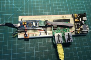
Sensors Node used here as dongle for the Raspberry pi
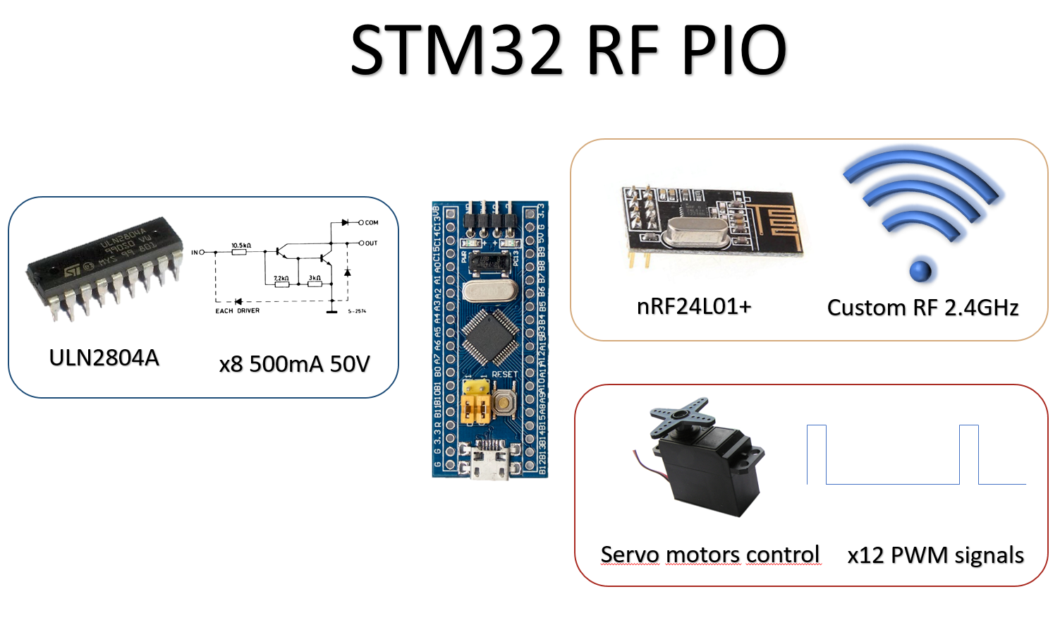
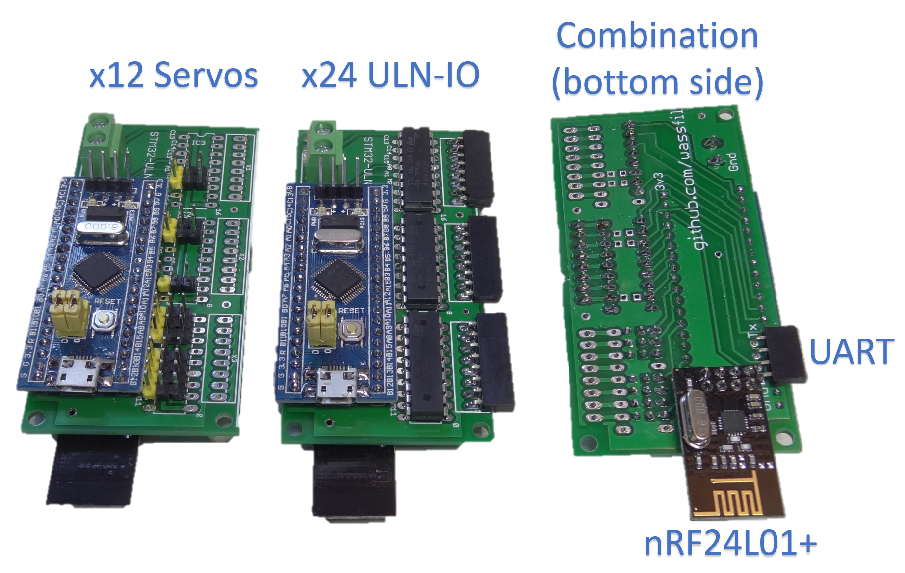
STM32 RF PIO Concept
- Smart RF controlled PIOs
- extensive PIO number x24 PIO s from which x12 PWM
- power outputs x500 mA 50V compared to uC pio of 25mA 3V
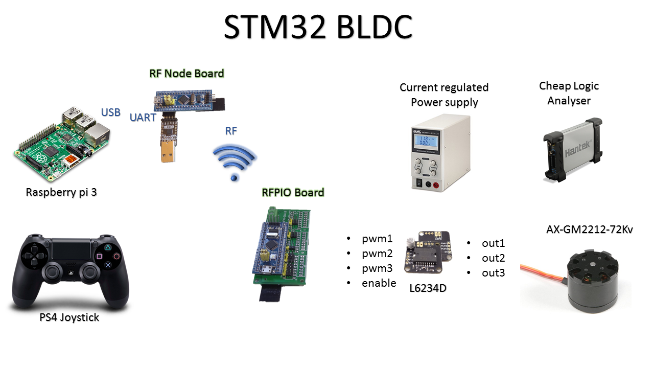
- RF Smart light control
- RF Servo motors control
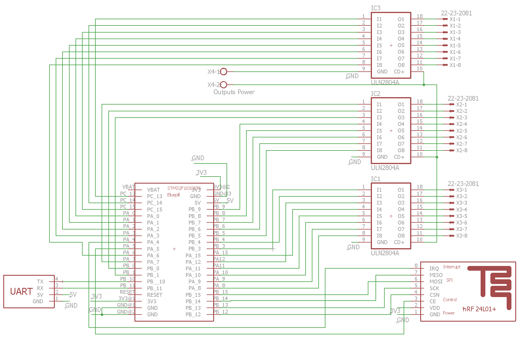
STM32 RF PIO Schematics
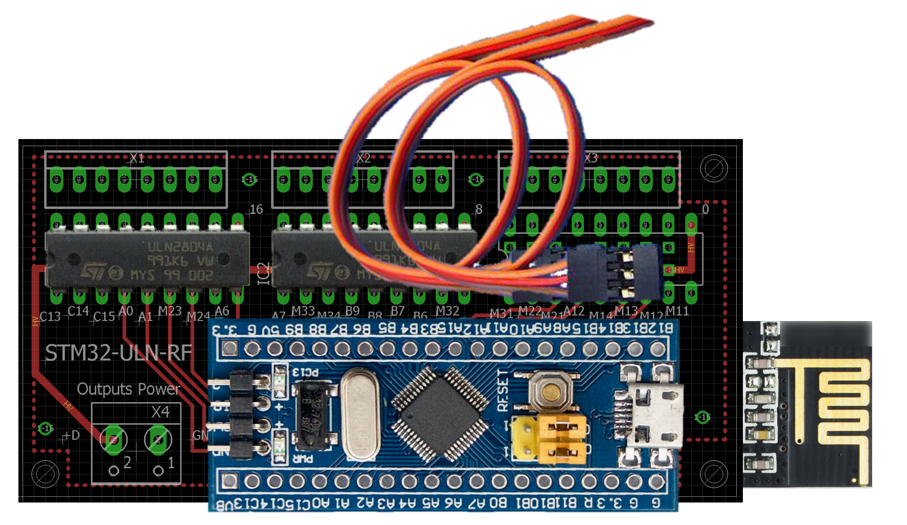
STM32 RF PIO Board
github linksize : 80 mm x 39.37 mm
- It is possible either to connect servo controllers cables or solder an ULN2804A in each of the 3 slots.
RFPIO PinMap
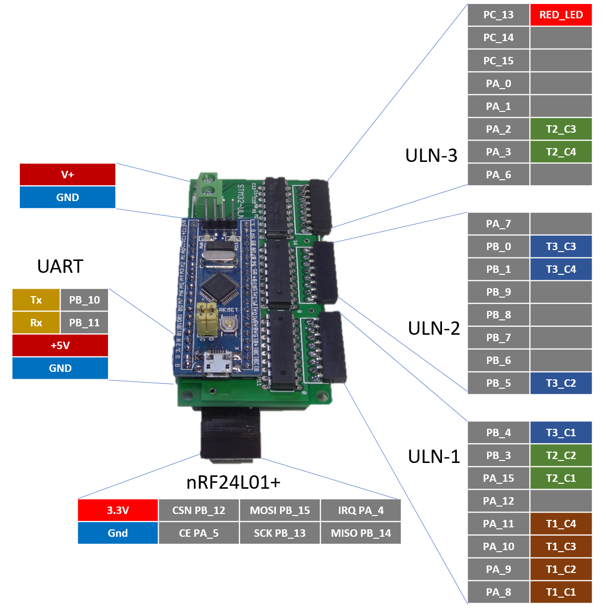
RFPIO Board Options
See this RFPIO bloard in action in this project
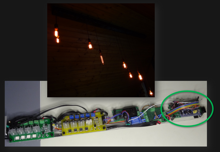
#STM32 BluePill x8 Edison Bulbs with nRF and MQTT
Existing STM32 Boards
Well this section is out of topic regarding the Bluepill, but given the fact that some boards are using the STM32, I'd like to keep them close here as a reminder for potential use cases and resources sharing:
- CC3D is based on the STM32F103CBT6, has an accelerometer MPU-6000 on board a Flash and standard connectors for serial i²c,...
- This hackaday project #Low power mesh networking for small sensor grids based on the STM32F051 with the nRF24l01+
 Cees Meijer
 Mateo Estigarribia
 Ruslan