Close
0%
0%

Laser proximity/distance sensor

Short range laser distance/proximity sensor

Similar projects worth following
This project is a nicely separated subsystem of another project I'm working which requires short range distance measurement.

Sensor module specifications:
- Up to 2m range (indoors),
- 3 % accuracy in high accuracy mode (~1.2m range, indoors),
- Multiple profiles for different applications (fast acquisition rate but lower accuracy and range or slower acquisition but more accurate at longer ranges),
- USB (CDC) and TTL serial outputs,
- 3.3 to 5.5V power input.

This project aims to solve a common problem: bits are very bad at measuring distances by themselves. They need help of some cooperative atoms to solve this existential issue.

This project is a documentation of one such collection of atoms (ironically, expressed as bits).

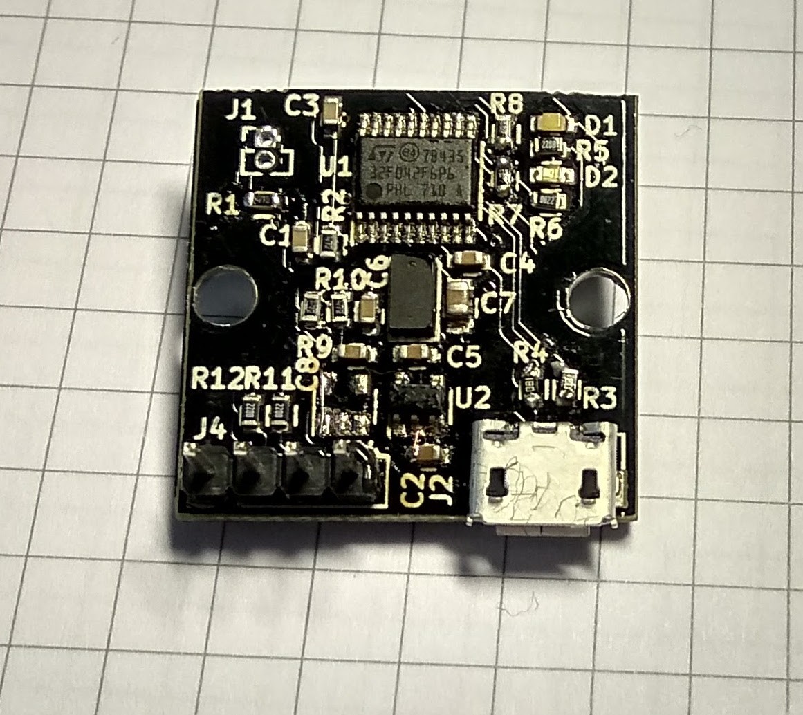
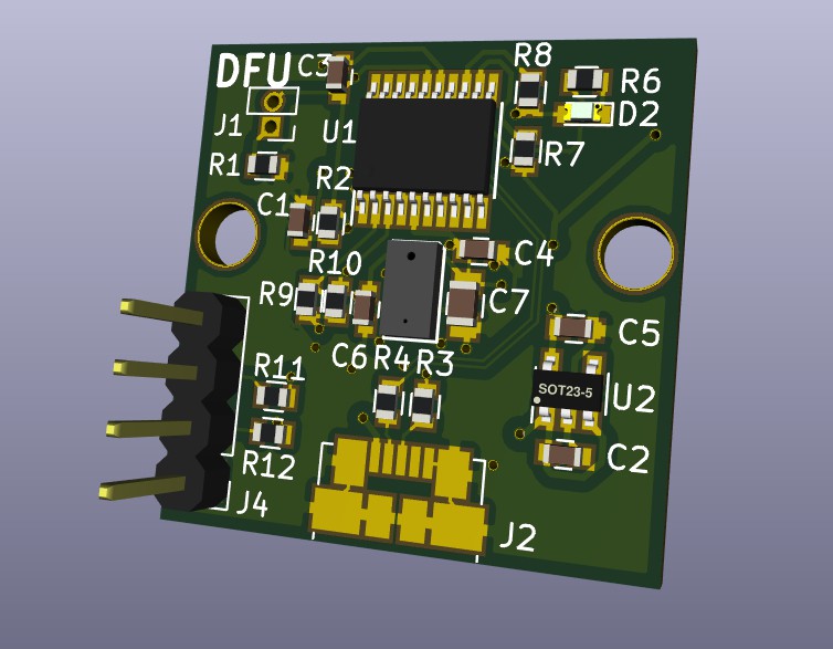
In other words, it's a distance sensor. It's not world-changing by itself and is just a humble component of some larger system that I'm working on.

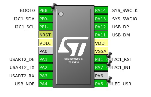
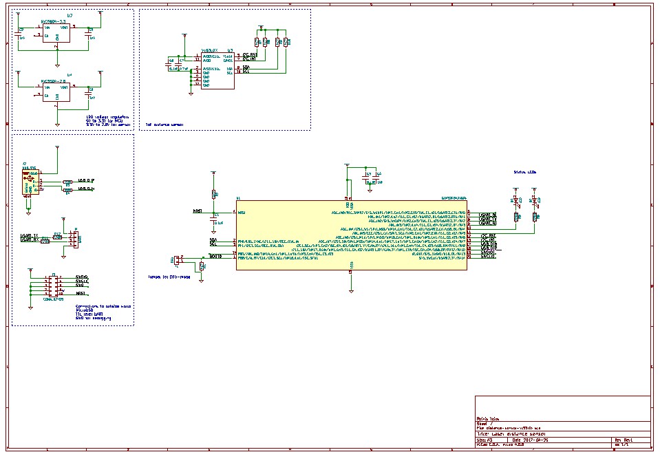
The project is fully open-source- both the hardware and software is permissively licensed allowing anyone to build upon it. The only restriction comes from me using STM32CubeMX to generate pin & peripheral configuration for firmware side of things. But that is just because I'm lazy and want to move on the interesting project where this sensor will be used.

  • 1 × STM32F042F6 ARM Cortex-M0 microcontroller with USB
  • 1 × VL53L0X STMicroelectronics laser-based ToF distance sensor

  • Built the first revision hadware

    fest09/09/2017 at 10:43 0 comments

    The first revision of the hardware has been built and basic firmware which configures the sensor and outputs sensor readings over USB and UART has been written. The good news- it's functional. The bad news- this won't be the final hardware revision.

    The assembly is not too pretty due to having it reworked multiple times- the initial components were soldered in toaster oven, but I soldered the VL53L0X after that, from some other boards I had been working on.

    There are three fuckups hardware changes:

    • For some reason, I assumed that voltage regulator's enable input can be left floating. Oops, it has built in pulldown resistor, so I needed to tie the enable input to Vin.
    • While PCB was being manufactured, I decided to test VL53L0X sensor operation from 3.3V, as I noticed that many other projects around it don't bother with powering the sensor from 2.8V in 3.3V systems. I could not discern any measurable performance difference (the power dissipation seemed to be a bit higher but that does not matter in this project).
    • Selecting DFU mode with BOOT0 pin requires high voltage level, but I had wired ground to jumper's other pin.
    • As I'm pretty sure USB will be the main reason someone would use this board instead of plain breakout board and having some unused space on board due to removing the other regulator, I wanted the USB connector to be centered.

    The new hardware revision has already been produced and is now being shipped to me.

  • Hardware design

    fest04/24/2017 at 21:52 0 comments

    The main system components are VL53L0X distance sensor and STM32F042 micro-controller (MCU). This MCU is one of the smallest ARM Cortex-M0 parts with USB, but still comes in hand-solderable TSSOP-20 package.

    Since I have used this sensor and a micro-controller from this family before, I had a good idea on how they both work, so the hardware design was relatively straightforward.

    I have found STM32CubeMX pin configuration tool to be very helpful while designing hardware using STM32 parts. It allows to enable all required peripherals and visually see which pins are still free.

    The biggest hurdle is separate power rail for VL53L0X (recommended operating voltage of 2.8V). It would be tempting to power micro-controller from the same 2.8V rail, but STM32F042's USB is guaranteed to function for at least 3.0V power rail.

    While it would probably be fine to power both of them from a single 3.0V rail, I decided to power MCU from 3.3V and sensor from 2.8V.

    I2C bus between them is pulled to 2.8V. High logic level for MCU for the pins I'm using is 0.5 * VDD + 0.2 ~= 1.8V which is well below 2.8V at which the I2C bus is pulled to.

    I chose the ubiquitous MIC5504 series low-dropout linear regulators because they are cheap and have very low dropout voltage.

    Schematics

    The hardware design for revision 1 is finished and Gerber files are sent for production.

View all 2 project logs

Enjoy this project?

Share

Discussions

eorlian-medy wrote 07/15/2021 at 08:05 point

Wow What an interesting and unique idea on that you are working I will recommend you to carry on working on it just like I am working on rangefindere project you can see here.

  Are you sure? yes | no

psegrippers wrote 07/13/2019 at 17:18 point

Detalhes Ola , muito interessante seu projeto ,  qual a distância pretendida?

Temo uma necessidade para  esta aplicação .

Ma dificuldade esta no consumo de energia de seu sistema e do laser .

Para uma distancia de 1500 mm qual sua Sugestão?

  Are you sure? yes | no

EngineerAllen wrote 09/09/2017 at 20:42 point

why not just $2 ultrasonic sensor over uart?

  Are you sure? yes | no

fest wrote 09/10/2017 at 09:18 point

Ultrasonic sensors have some inherent characteristics which make them unsuitable for certain applications: relatively wide "field-of-view", echoes when used indoors, need for synchronization when using multiple sensors.

The sensor used in this project has it's flaws too, but they are different (smaller range is one of them) and it's just more suited for my intended application.

  Are you sure? yes | no

EngineerAllen wrote 09/10/2017 at 20:17 point

ok thanks

  Are you sure? yes | no

Similar Projects

Does this project spark your interest?

Become a member to follow this project and never miss any updates