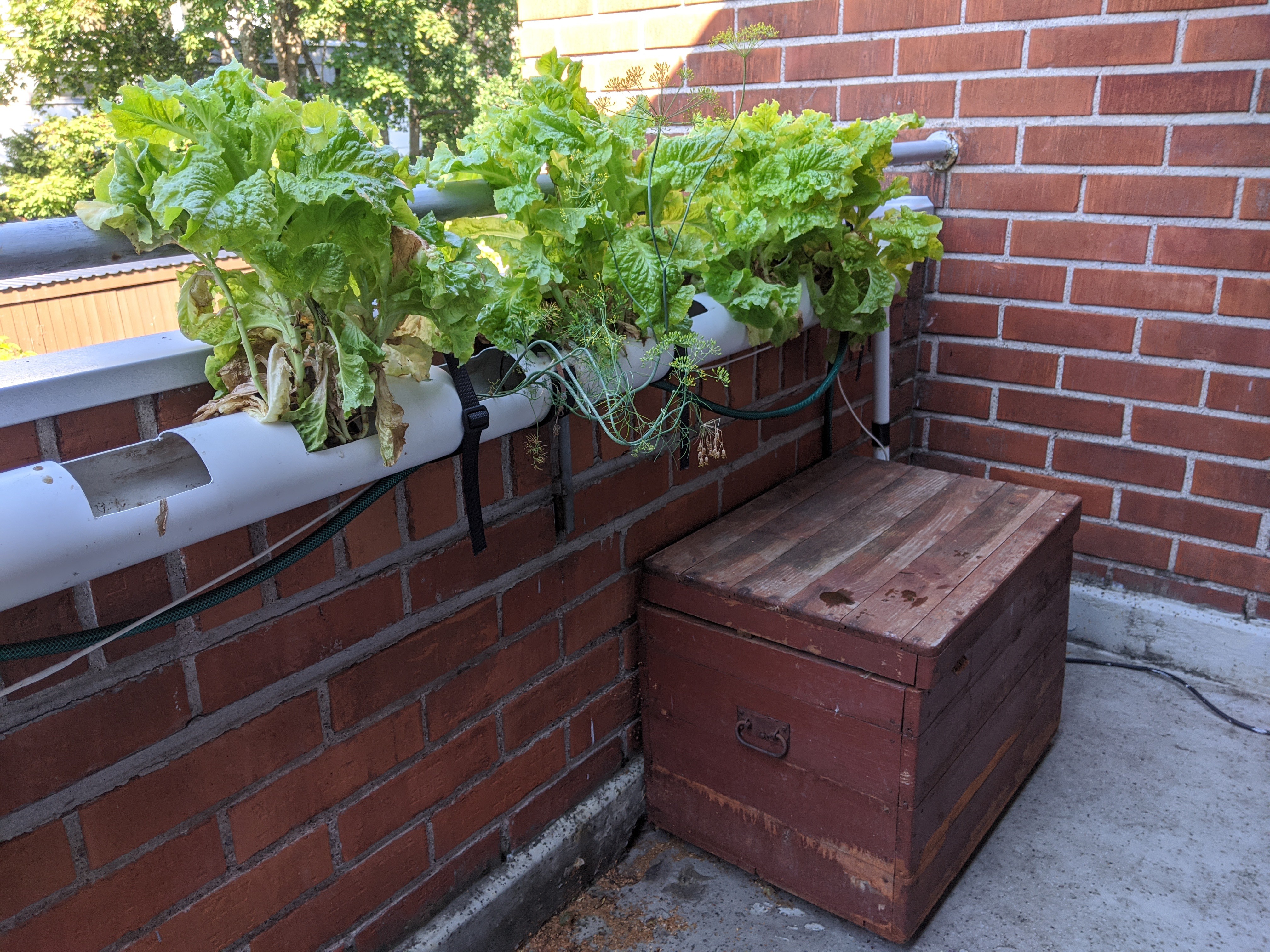
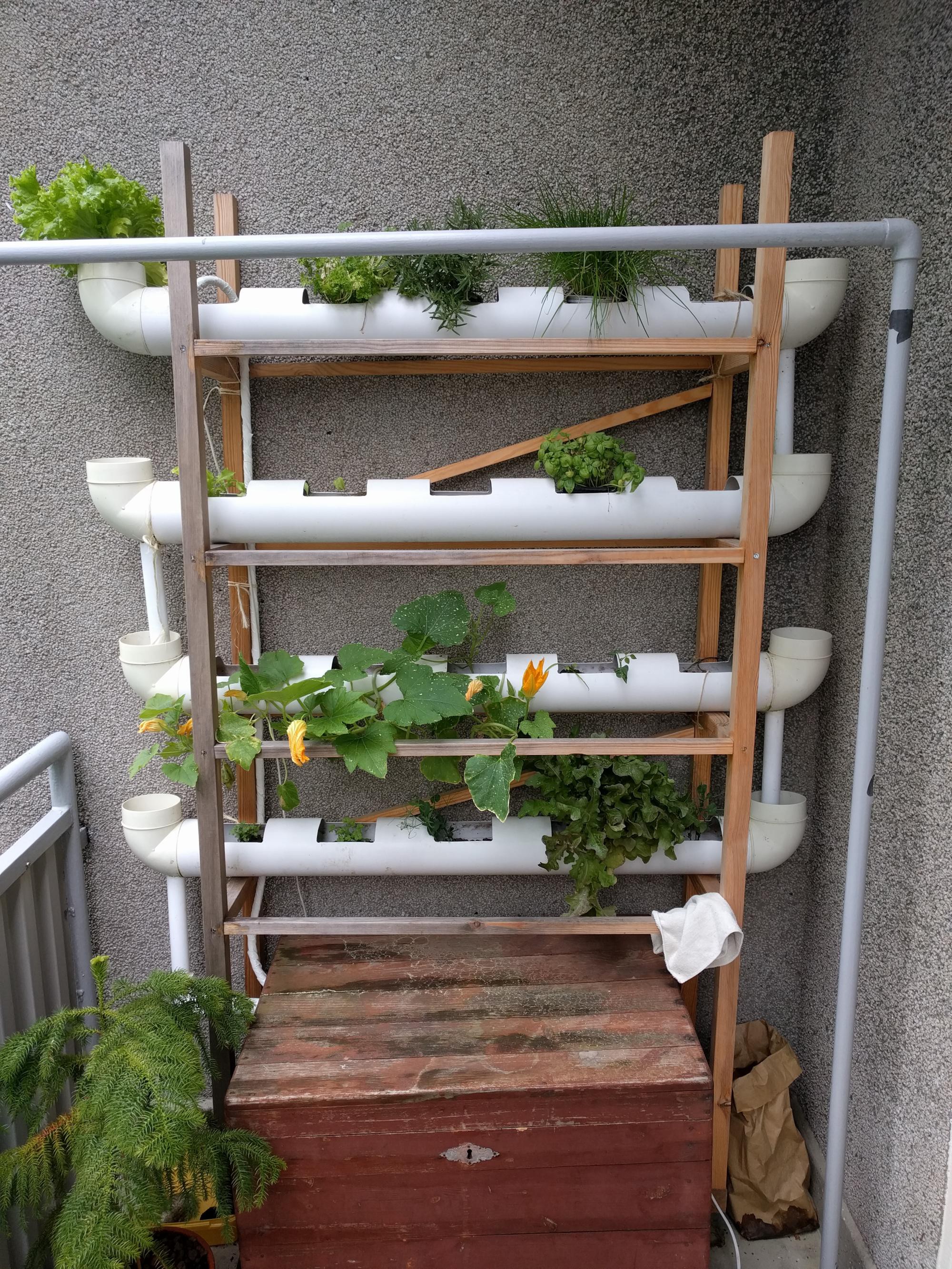
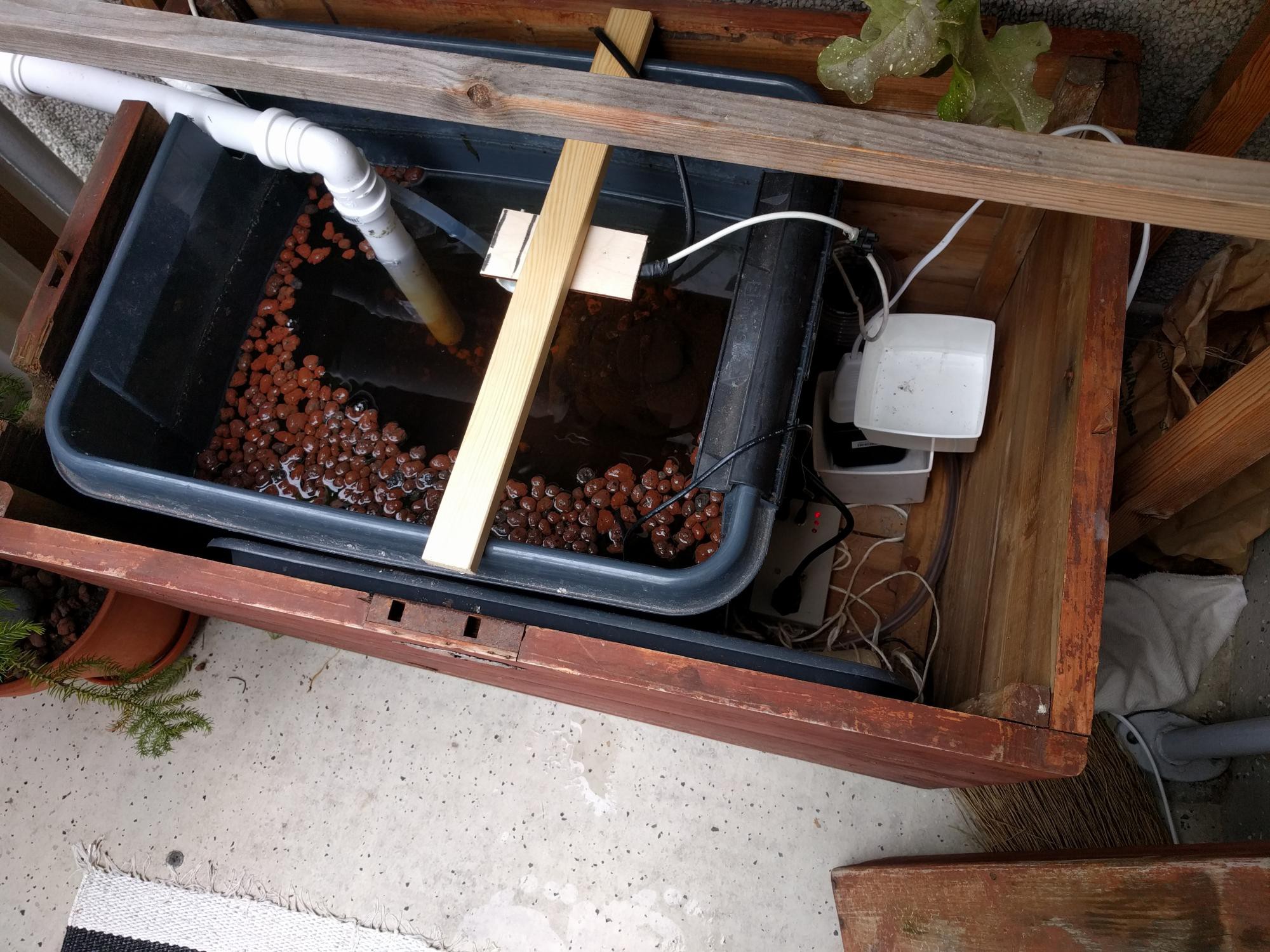
• Update 2020

    Pauli Salmenrinne08/16/2020 at 09:39 0 comments

    Well it has been few years, but guess what, the system has been running again after pause of few years (because of fresh family member and moving to larger apartment - life).

    I have pushed some github updates, most importantly fixing some thingspeak and email send issues after compiling with updated toolchain (the certificates on ssl-connections caused certain issues).

    I also improved error handling; now we reboot after error and delay and reboot also if wifi-is lost for too long. It has been running with some errors for full summer, but no single manual reboot was required. The errors have been "water level not up after pump time", and when i last checked there was pretty much algae on the sensor. Maybe part of issue. Anyway, its recovering.

    The system has been also modified for full vertical installation (thanks to bigger balcony). The issue become installing the pipes together. I made 6 versions with 3d-printer - but none of them were durable enough (seems like pressure + 30C == pla not holding up). And water leaks were too often. Now its with metal tightener + pla structure + food plastic for water insulation. Seems to work but the PLA still changes shape.


    The grow season has been going nicely, some issues to think over for next season:
    • Larger plants roots do not permit the water to flow, causing stuff to dry on other side and flood on other.
    • The end 'filter' requires cleaning at time to time
    • Now i had small rock-wool + leca pebbles on small pots, but this is not very good. Dill for example seems to be prone for overmoisture when small and fall down when larger. Pure sand with rockwool to fill lower holes?
    • The larger plants with smaller roots fall down easily and then dry and die.


  • Growing season summary

    Pauli Salmenrinne09/24/2017 at 18:17 0 comments

    Winter is coming. I tore down the setup for this season. The device worked fine, some notes:

    • Single weird "no error mail" - error state with no email. I though it was due error during boot, when wifi was not up yet
    • Single weird "device down" - no response, booted up fine. No explanation.
    • Single error from distance sensor, it was sunked on the water. Putting it back to place it worked fine
    • The "water detect" switch failed few times - due filtering. It did get water, but it went to -1 due the 0,1,1,0,1 readings. Maybe some better filtering required there (running mean?)

    Some todos:

    • On error case, we maybe should allow manual "retry" or "reboot" options for remote "fixing"
    • Logging needs to be pushed on remote server. The error email sending maybe would make sense more there. That way we would not need to latch the error email
    • Water switches maybe should be on each "level"
    • The "manual on" switch is nonsense - i can just transfer the power feed from board to pump.

  • Field testing done

    Pauli Salmenrinne06/13/2017 at 14:34 0 comments

    The field testing - phase 1 - is now done. The unit has been deployed and after minor fixes its now up-n-running nicely. It was deployed on 6.6. so it has been running for a week. Some fixes/changes:

    • Water level switch was inverted - luckily i had code ready, just change false -> true
    • The thingverse logging was not good, improved

    The latest version has been running only for day or so, lets see. The thingverse logging was changed from 15min interval to

    1. If pump state changes -> push
    2. If draining is done -> push measurement
    3. Push if not pushed in 15min

    This means that night time it will push in 15min delay, and during day it will push every pump-time (assuming <=15min, that is the case here). I also added new measured delays: delay of water detect to go high after pump has been switched on, and delay of water detect to go low after pump has been switched off. I hope to see a) pump wearing and b) roots filling up the tube from these figures. Lets see how it goes.

    But the most important part is here, pictures:

    Picture 1: The full system. Water is pumped from the red container to upmost tube, where it slowly flows back to the container. The water detect switch is located at the pumping location.

    Picture 2:And here you can see the water container and the controller little red light.

    I am bit sceptical about the HTTP server from the ESP8266 library, since i think its not taking account DOS attacks in any proper manner. If i find my self with too much free space i might bake my own memory and security hardened arduino-esp-http-server.

    And now starts the hard part ; endurance testing. Lets see if it works through the cold Finnish summer.

  • Ready for field testing

    Pauli Salmenrinne06/03/2017 at 06:44 0 comments

    Now i have finished 'desktop' testing of the software and hardware. Some findings

    • GPIO16 cannot be used in INPUT_PULLUP. It just gets stuck (value not chaging). Adding external 10k pullup does the trick and does not seem to interference other stuff. There is 'INPUT_PULLDOWN_16' that is probably related to this
    • Email sending does not work inside of 'ESP8266WebServer' callback, probably due memory issues. For debugging purposes i added serial command line option. At this point having serial also on a connector on case would be nice .. The main connector would have two pins left (and GND is common) - lets see how much debugging is needed.

    Code updates:

    • Web page view updated - see picture below. It works in static html and the C++ backend is serving json stuff from "/get/status" and "/get/devices" etc. Pretty good. I can do all html and JS debugging locally, with "python -m SimpleHTTPServer 8000"
    • Otherwise debugging was pretty smooth, thanks to unittesting. Some prettyfications and someclear hardware-software glitches (like HC-SR04 sensor does not work with delay() it is delayMicroseconds())
    • I added ThingSpeak support. Now a push (HTTP GET) is made every 15min. Its free, it has graphics included, seems good enough.
    • I had also one 'email busy send loop' - got around 30 emails "sensor failing" to my gmail. Nice. I added limit of 3 emails per boot to not have it again.

    Next: testing with the real thing (i have hydroponics stuff ready, now running with off-the-shelf timer).

  • Stuffed inside too small case

    Pauli Salmenrinne05/24/2017 at 17:35 0 comments

    Here is the hand drawn circuit diagram, i'll document it here since i am going to loose the original one anyway. Pins are proper but changes were made on the X1 corner to fit the caps, and the push button was replaced with a jumper for space - since the rtc needed to be moved upwards to make space for 'screw headers'.

    And here is the case. It has three leds - power, esp alive, and pump off (=inverted due NPN transistor). The case is too small, naturally, but it seems to be pretty firm when stuffed down. The nice looking connector is from dumpster diving. You can also see the professional looking ;) universal glue casing i made for the HC-SR04 ultrasound. I though it would be good to have some protection there since its going to hang over the water container. The switch is "manual on" - a switch to force the pump on for reason or another.

    Now, back to code.

  • First protoboard alive

    Pauli Salmenrinne05/17/2017 at 07:03 0 comments

    I have been soldering the first protoboard. Today morning, when power applied it woke up and everything seemed to work. I have almost up to date schematics on pen-n-paper style, but i think i will not draw them clean, unless requested. Some hardware changes:

    • China adjustable buck-converters arrived - these seems to work nicely, though when plugging in the raise time (after two 470uF caps) is quite slow, some hw to keep reset down while voltage is low would be good
    • I replaced the LM35 temperature sensor with HTU21D that i found from my stuff - its digital 3.3V I2C connected temperature and humidity sensor. This leaves the (bad) ADC available, and it could be used for say light intensity monitoring.

    I also updated the first code to github, that contains the current 'testcode' -- its to be fully rewritten. This one is for proof-of-concept and hardware verification.

    I stumbled a bit with memory on the ESP, seems like the WiFiClientSecure (that is needed to send email via google smtp) is a shitty library. For debugging purposes i had my logs ringbuffer quite large -> memory quite low, and the board seemed to throw exception with no good reason when trying to send the email. Shit.

    There are few more jump-wires to be connected but then the (board) hardware is done. Other hardware stuff needed is to make case for the ultrasound ranger (measuring water level) and something for the 'water switch' (making sure water appears on the top, and pipe is not disconnected).


  • RTC timer hooked up

    Pauli Salmenrinne05/03/2017 at 18:36 1 comment

    Ok, now i received a tinyrtc module from China. Seems like i did pick bad choice; this version requires +5V to work. And on top of that its made for LIR2032 rechargeable battery, and the China shop shipped it with "rechargeable CR2032", that i belive to be just normal CR2032. To avoid any troubles, i soldered some components of (include +5V pullups on the I2C bus) as described here:( source: google gave me this but i think i found it on some discussion thread)

    While getting the chip connected i first tried with GPIO16, but it seems like (after googling) there is something special with that pin, using pins 14 and 12 works fine.

    Anyway, i need +5V rail for the HC-SR04 and LM35 so its no trouble. The (adjustable) buck-converter have not arrived, when it does i have all the components i need to make first proto board. I'll use the buck-converter to power +5V and then use linear regulator to get the 3.3V for the ESP.

    I also managed to use the platformio data/ folder, that works fine as long as you remember to call SPIFFS.begin() before assuming anything to work. I dumped CSS and index.html file there and i am using the C++-code to provide json - get api for the static html. This way i do not have to hardcode any html to the C++ side, which is nice.

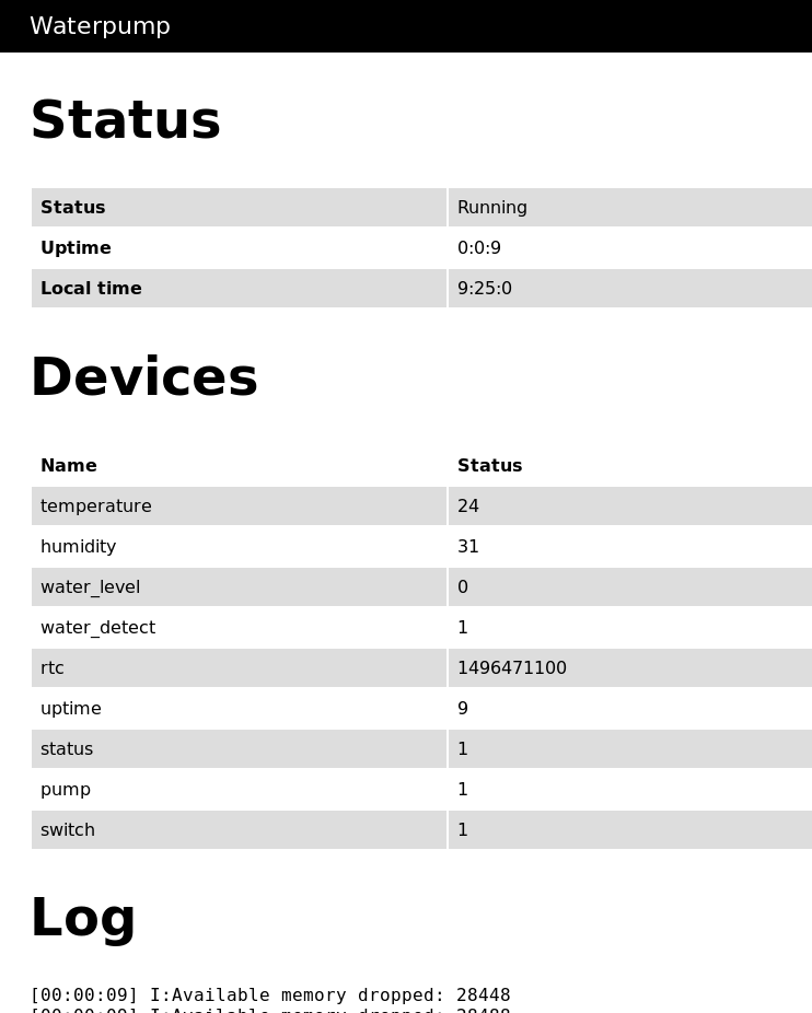
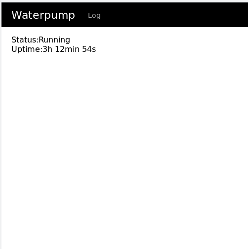
    Here is screenshot of the current main page. Simple.


  • Status as for now

    Pauli Salmenrinne04/25/2017 at 17:58 0 comments

    Leassons learned so far:

    • I had to add 5V rail since i was unable to get the HC-SR04 to work with 3.3V supply that i use for the ESP.
    • The ESP ADC works as fuck. I calibrated it today - since it was givin spoof results for my LM35 temperature sensor.
    • Platform.io works nicely to program the device. OTA (over the air flashing) works out of the box. Super!
    • If you forget to 'free' malloced buffer you will get the device to reboot with uninformative stack trace
    • Boots did happen, sometimes OTA update failed or jammed (causing software watchdog reset) after re-adjusting the power supply and adding capacitors it has at least come very rare.
    • Regulators are not suited when trying to get voltage from 12.0 -> 3.3v. They do really heat up with ESP. Like burning hot. Even with heat sink on. I have ordered these "buck converters" that do other than heat with the extra voltage - but shipment from China is not too fast..

    Material damage:

    • Voltage regulator condensator blew up - inversed connection while doing the 5V rail. Luckily no damage, but huh. I would not expect that much of explosion.
    • LM35 was almost destroyed as it was reversed (the specs said BOTTOM not TOP view, uhh.
    • Breadboard power supply regulator by feeding 12v input to get 3.3v output. It burned the poor thing.

    Figure 1: The ADC values calibrated with potentiometer. UP-DOWN: the value red from analogRead, LEFT-RIGT: The voltage measured with multimeter.