Adam Gulyas
At this point, the most noteworthy part of this project is the spice model, shown to the left at the top. A lot of effort was expended to research, understand, and then fine tune each sub circuit.
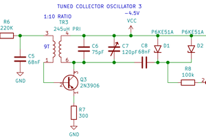
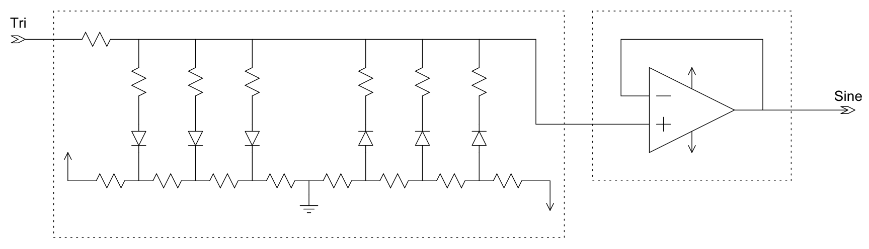
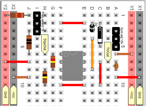
The design is broken up into several sections. There's the triangle core, which produces the triangle and square waves, and then four wave shaping circuits which take the triangle and square waves and turn them into something else. There's also the LED drivers, which are connected to the triangle wave. They should show (at least at the lower frequencies) if the circuit is oscillating and how fast.
One part that isn't shown are the buffers. The amplitudes of each output waveform are different, and I want them to be 20 Vpp. Each buffer's gain will be tuned to give the desired amplitude.
I will post a project log as I breadboard each part.

 Ellie T
 Ted Yapo
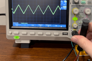
 CustomElectronics