Gintaras Valatka
Make "Uber Potentiometer" by using 2x LEDs & LDRs
A---|\/\/\/\/|---TAP ---|\/\/\/\/|---B
Move not only the TAP between A & B, but change the resistance of the POT itself !
Easy Variable Gain OpAmp control?
[ In the quest of making programmable Lab ]
First use case: controllable vRef for Adc
todo: test it in signal chain
Already have an account? Log in.
To make the experience fit your profile, pick a username and tell us what interests you.
Make "Uber Potentiometer" by using 2x LEDs & LDRs
A---|\/\/\/\/|---TAP ---|\/\/\/\/|---B
Move not only the TAP between A & B, but change the resistance of the POT itself !
Easy Variable Gain OpAmp control?
_74hc4067.inoArduino sketch filex-arduino - 2.10 kB - 04/26/2017 at 08:30 |
|
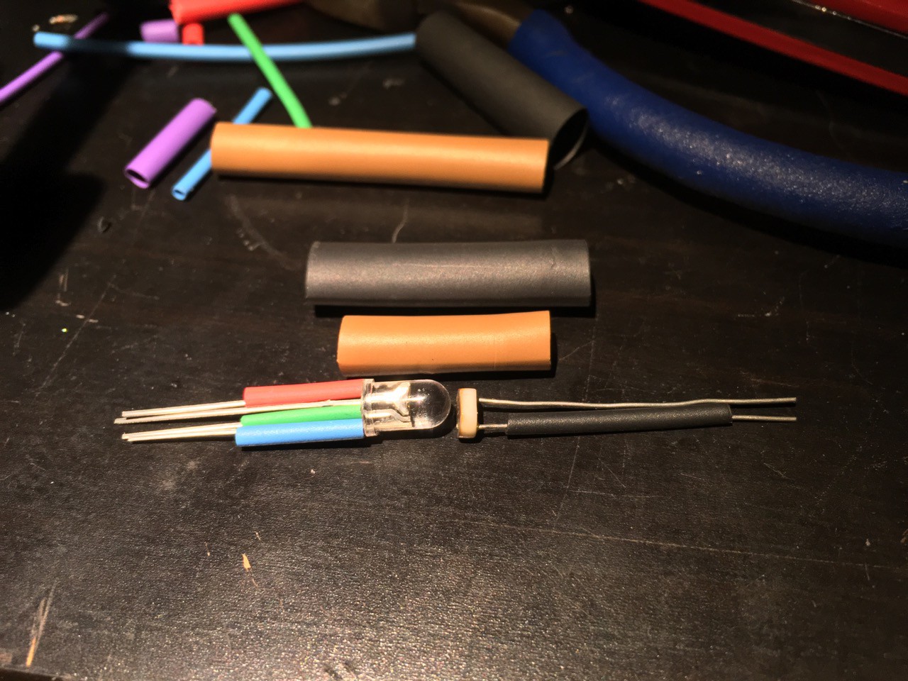
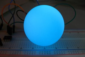
RGB LED & LDR double insulated from any light with heat shrink tubing and almost ready for PWM - I used common anode(in my case - Arduino Due) As the board reboots, I get all the lights ON 'clipping' until the server connects to the board.
TODO: find the best LED resistor values for 3.3v & 5v
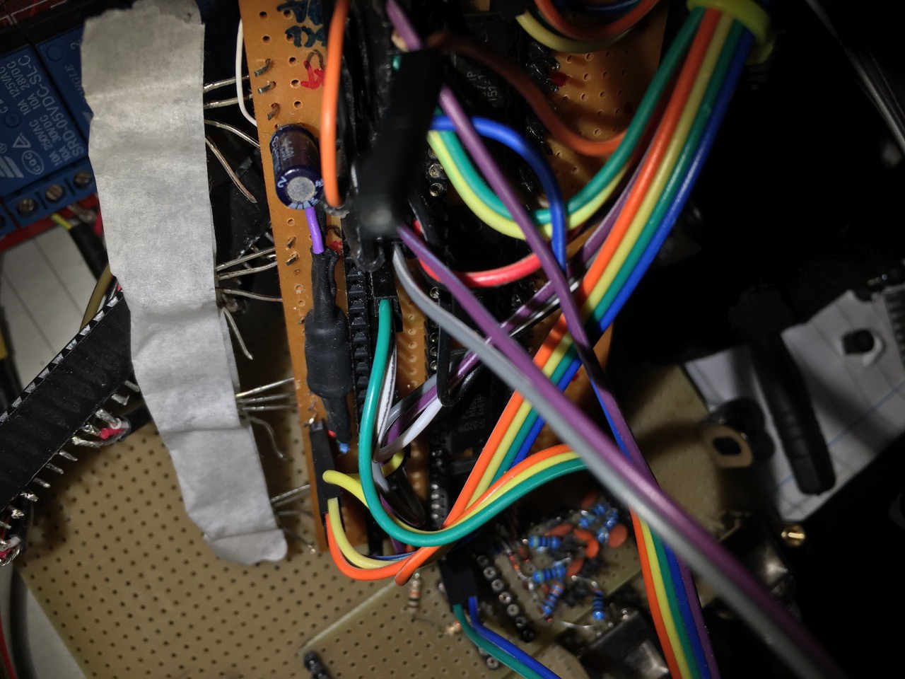
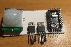
Variable Resistor used in GinScope for vRef. Can you see it? :D
https://hackaday.io/project/19374-ginscope-oscilloscope
GinLab = GinScope, GinGen etc - Program ∑ Control ∑ Run!
All that is needed is Arduino and unused digital pins. Having a bigger board like Mega could accommodate more LDRs. All that is needed is digitalWrite(). The same board can also drive PWM pins to drive LEDs that drive LDRs.. clear? good!
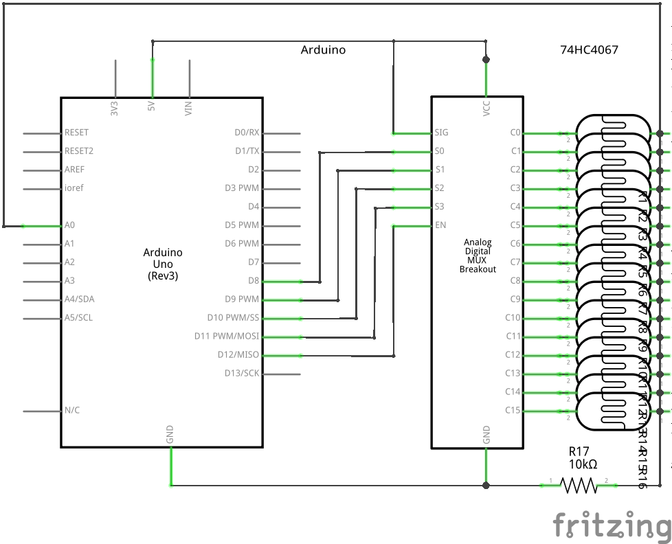
I wanted to have fun and used 74HC4067, 16-1 Analog Mux from Nexperia, http://assets.nexperia.com/documents/data-sheet/74HC_HCT4067.pdf
so the instructions part, of switching on/off 5vdc will be based around muxing, the rest is pure arduino, use anything that shines the light, use port expanders, go bonkers !
Yes, plugging Analog Mux Z pin(common input or output) to 5vdc and driving LDRs :D (it can do Digital multiplexing and demultiplexing too)
Connect and play, please bear with me while I'm Fritzing, in the mean time here is some video candy
No numbers can ever replace a nice plot!
Use data sheet to find out the peak spectral response and tune your LEDs to that wavelength.

Having unbranded and undocumented LDRs makes the whole thing much more interesting. Might write a sketch for doing just that, finding LDR spectral peak response using RGB LED etc
 brigadir