The Problem
The way in which a lot of developing countries do their water level measurements nowadays, is inefficient and inaccurate. In for example Myanmar, circa a thousand people are employed by the government to measure water levels at different locations three times a day and send their measurements by phone to a central station. The frequency of three measuring points per location per day is way too low and a reliable conclusion cannot be made. A higher frequency of measurements is needed to take different influencing factors into account like tides.
Commercial measuring systems are a lot more accurate and can send data to a database multiple times a day, but these systems are very expensive, they can cost a couple thousand dollars per unit!
The main goal of this project is to develop an affordable cloud connected measuring station to measure water levels in rivers and other types of surface water. Placing a lot of these low cost but accurate stations at different locations in for example a river, will highly increase the safety of people.
Challenges
Before starting this project, we came up with the following challenges that our measuring station will have to deal with:
- The station must be accurate to a level of centimeters. An accuracy of only a decimeter would not allow to differentiate between a flood or just higher water.
- The station should easily cope with severe weather conditions. High temperatures should not affect the accuracy of the measurements, and high wind speeds, rain and turbulent water may not destroy the station.
- The station must be self sufficient (solar power etc.). Because the station is placed in a watery environment and most of the times far away from civilisation, power supply via cables is very expensive.
- The system contains a lot of interesting components like a solar panel, so the station must be theft proof (this is a serious problem in developing countries).
- Total cost for this system should be less than 250 dollars. This will allow a developing country to place many of these units and improve usability.
How?
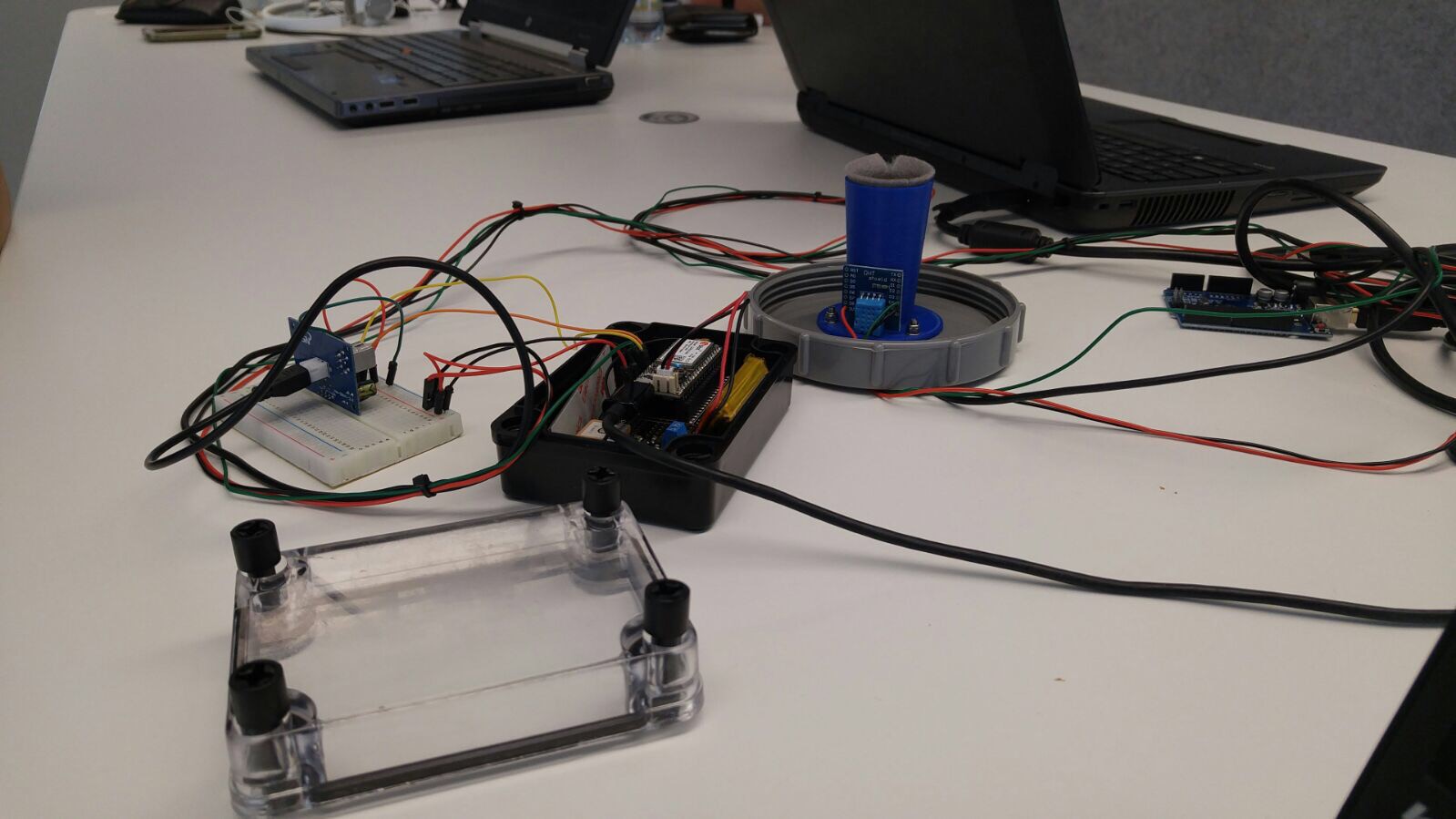
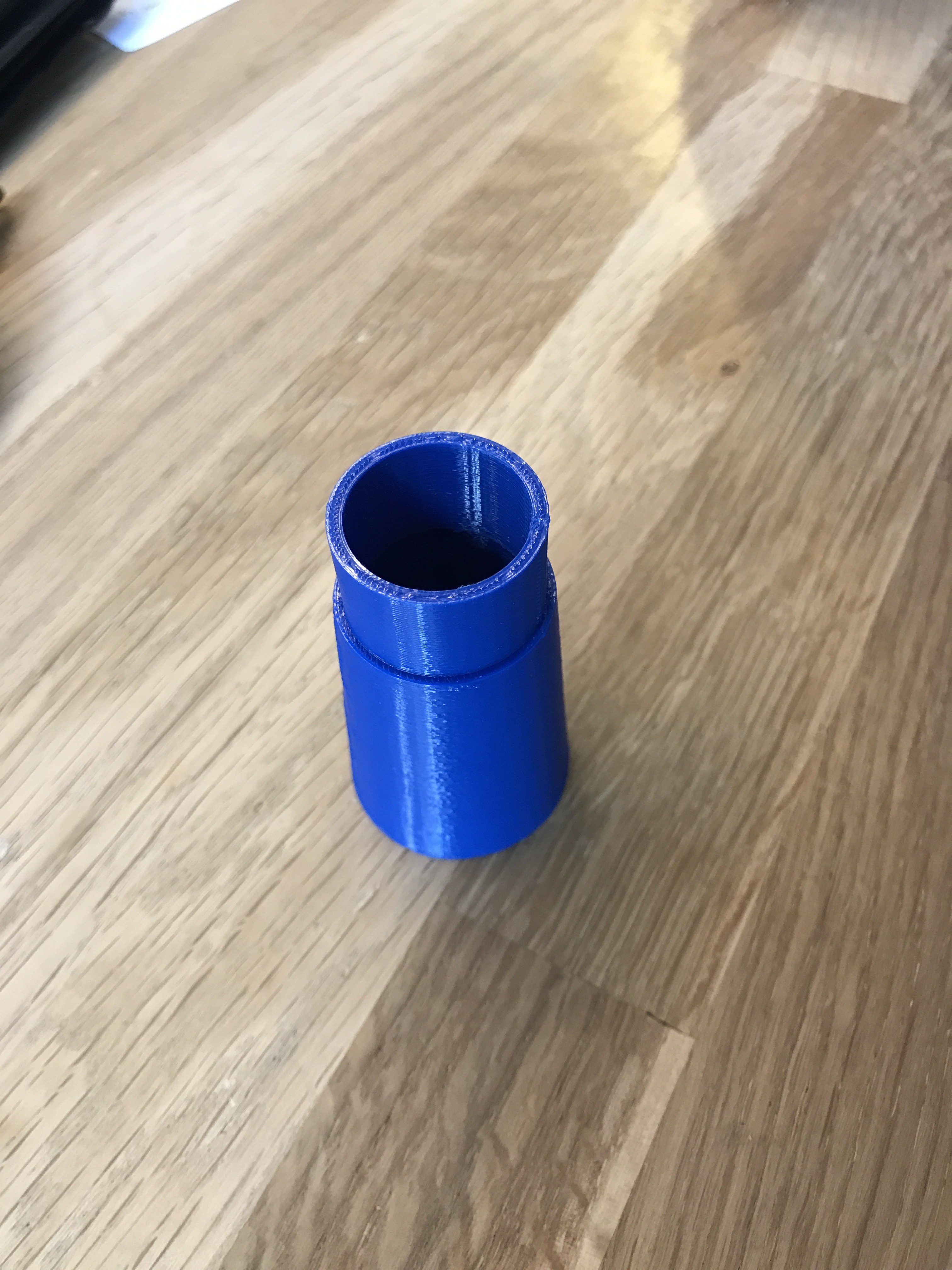
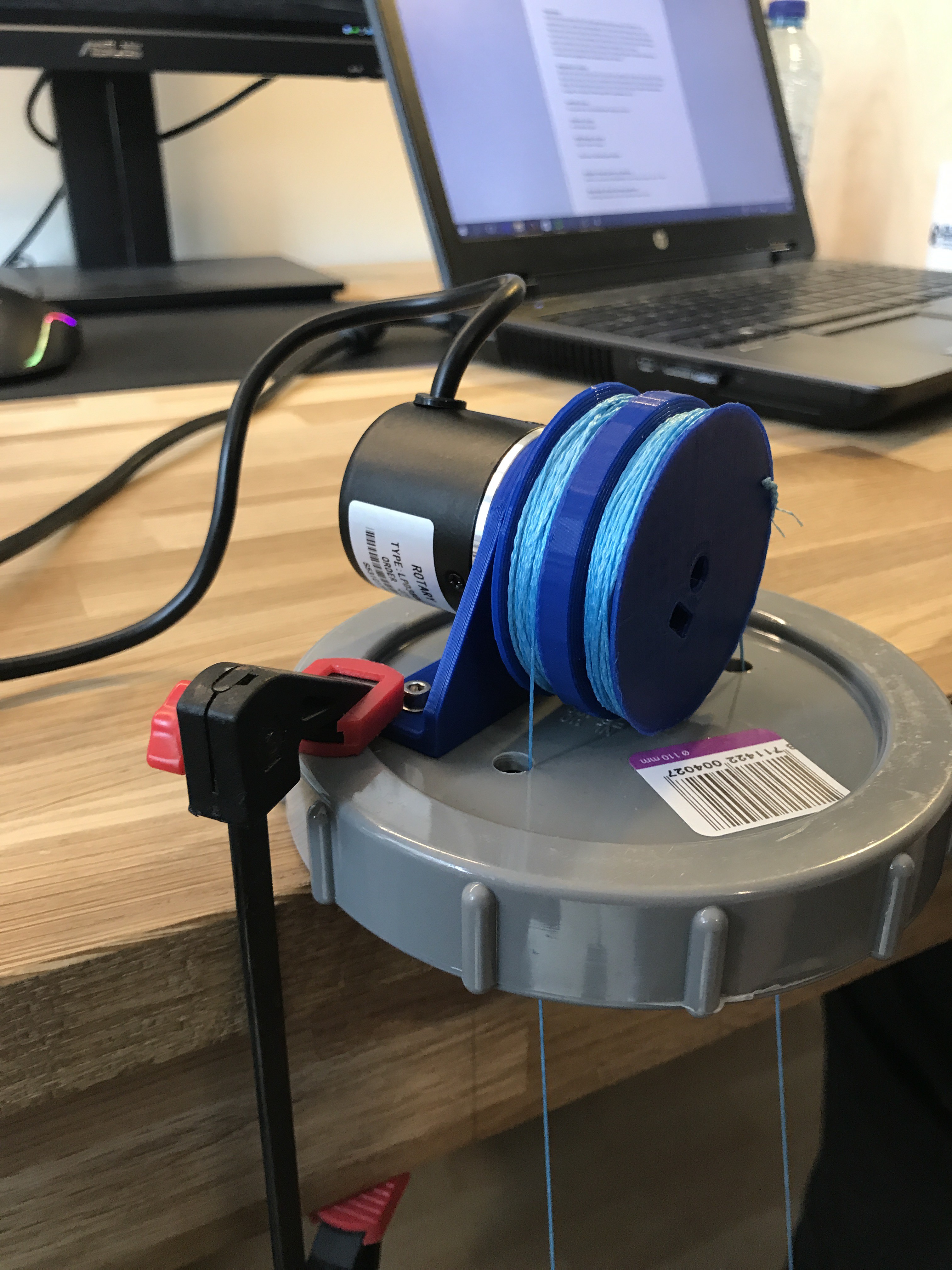
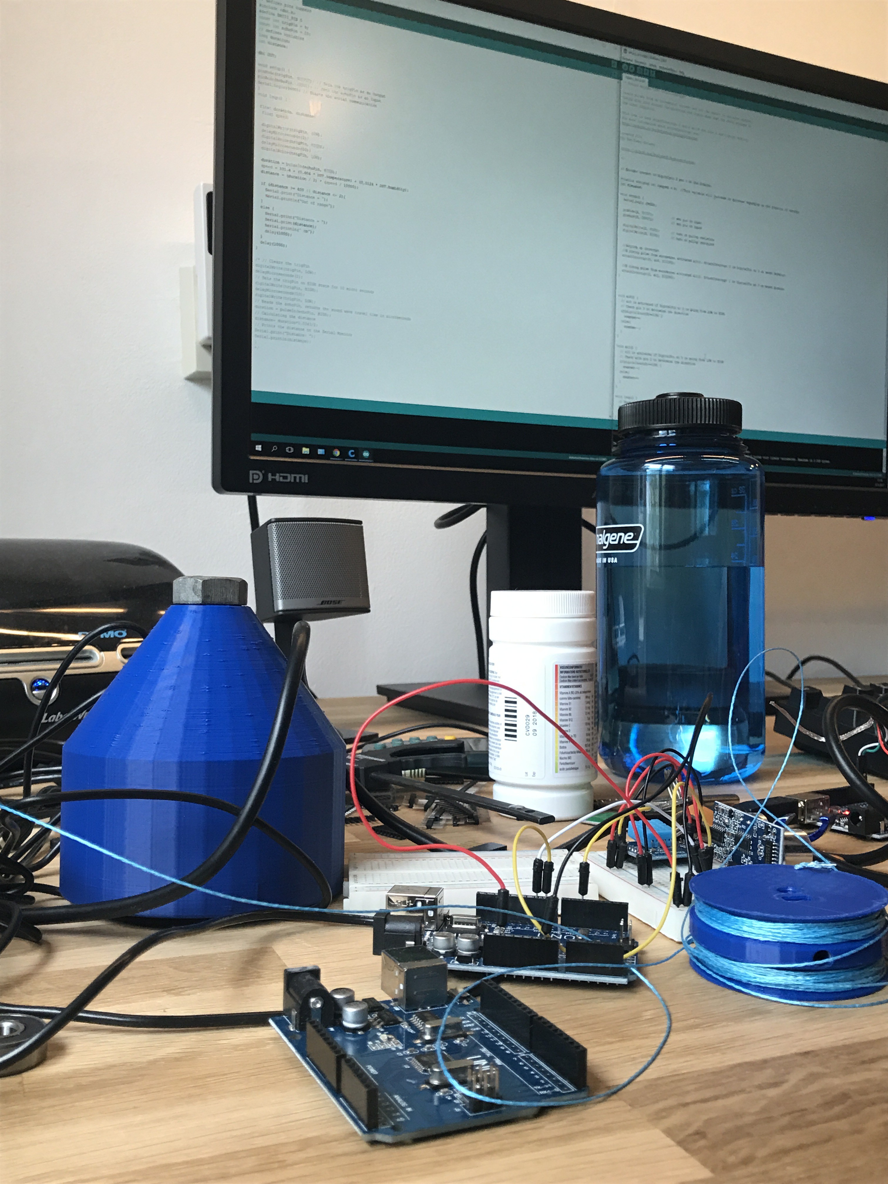
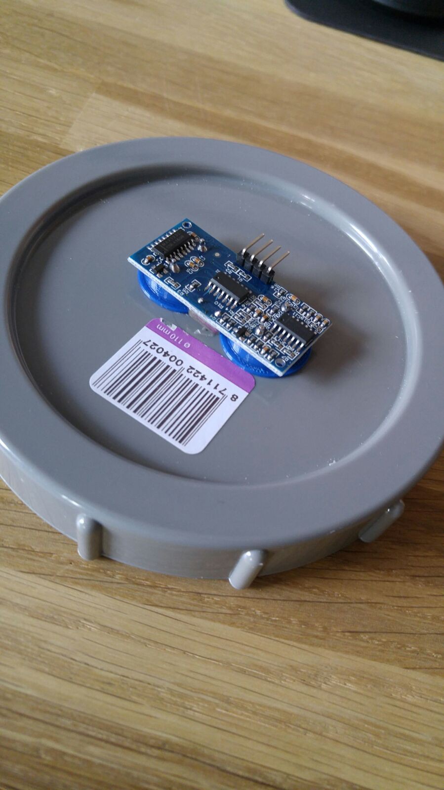
To start the development of our measuring station, we must first determine the right measurement method. There are several options such as pressure sensors, radar, ultrasound, laser and floats with pulleys and encoders. We will experiment with different sensors, to find the most affordable, accurate and reliable option.

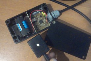
It is very important that the water meter stands on a weather-independent construction. For instance the electronics have to be dry all the time and it should not be blown away when wind kicks in.The data the water meter will collect needs to be saved first before sending it to a central station. The meter will not measure constantly but for instance 100 single times in five minutes. This is for energy sake. When using 100 individual measurements, the water meter should take the median of the data for the best approximation of the water level. Once per hour the water meter sends this data, using mobile network, to a central station. Once again, this is only once per hour for low energy consumption.
The energy will be provided by a solar panel. After transforming the energy of the sun into electricity, the energy will be stored in a battery which will be managed by a so-called Battery Management System.
To prevent the water meter from being stolen, all components will be hidden and locked. It only opens for maintenance reasons.
World Changing
Floods are still the cause of thousands of deaths every year. By better understanding of the water behaviour a lot of damage can be prevented. One way to prevent this is an affordable water level measuring station. It can warn people for floods, so regions can be evacuated on time.
This project can also bring economic progress, since the measurements of water depth can be used in the shipping world. If the water depth is known at all times, ships will not get stuck in low waters and loss of goods and ships can be prevented.
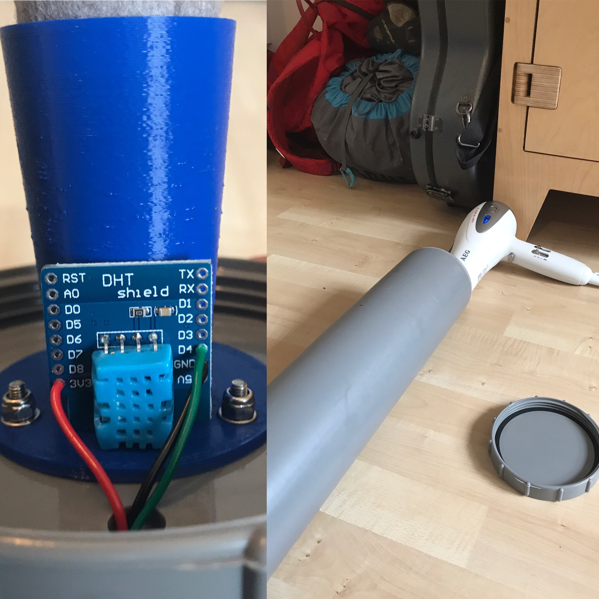
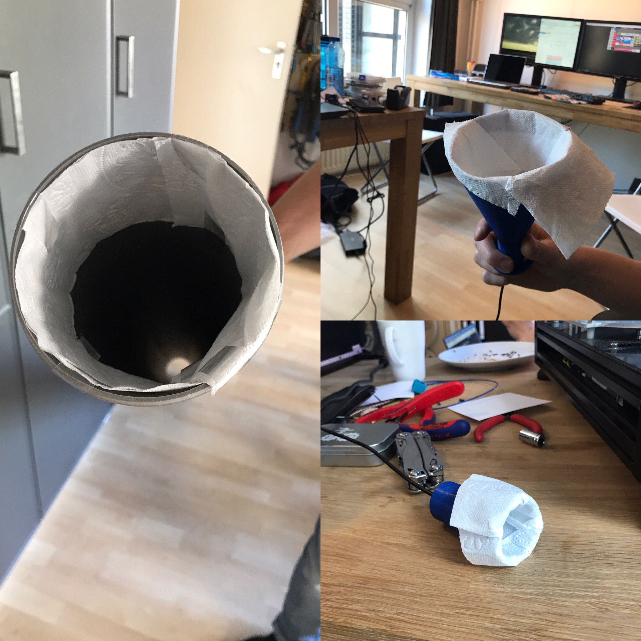
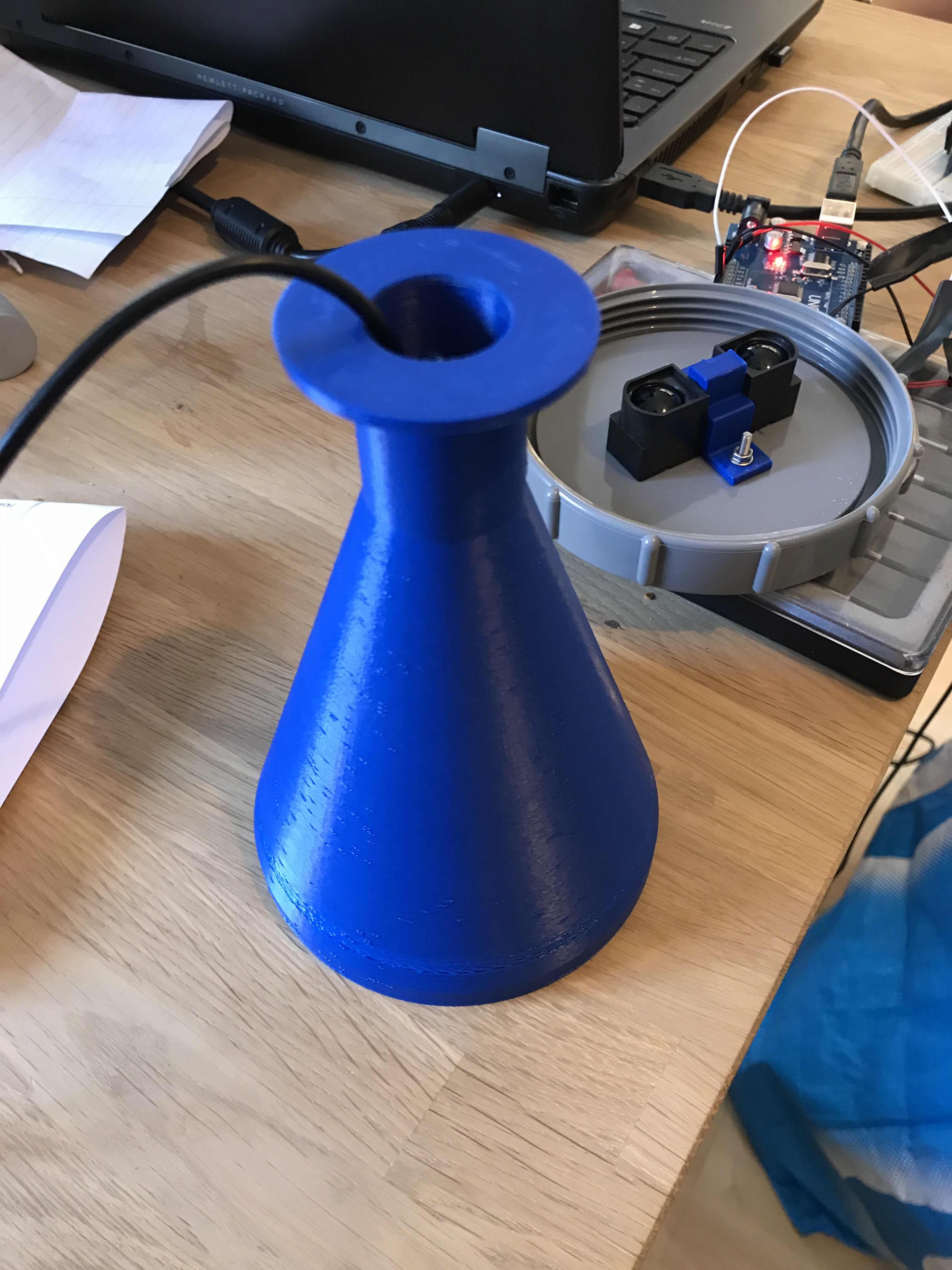
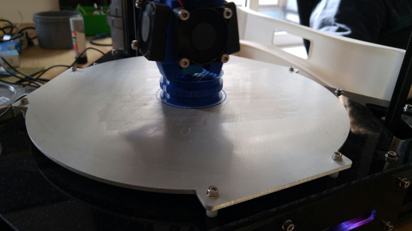
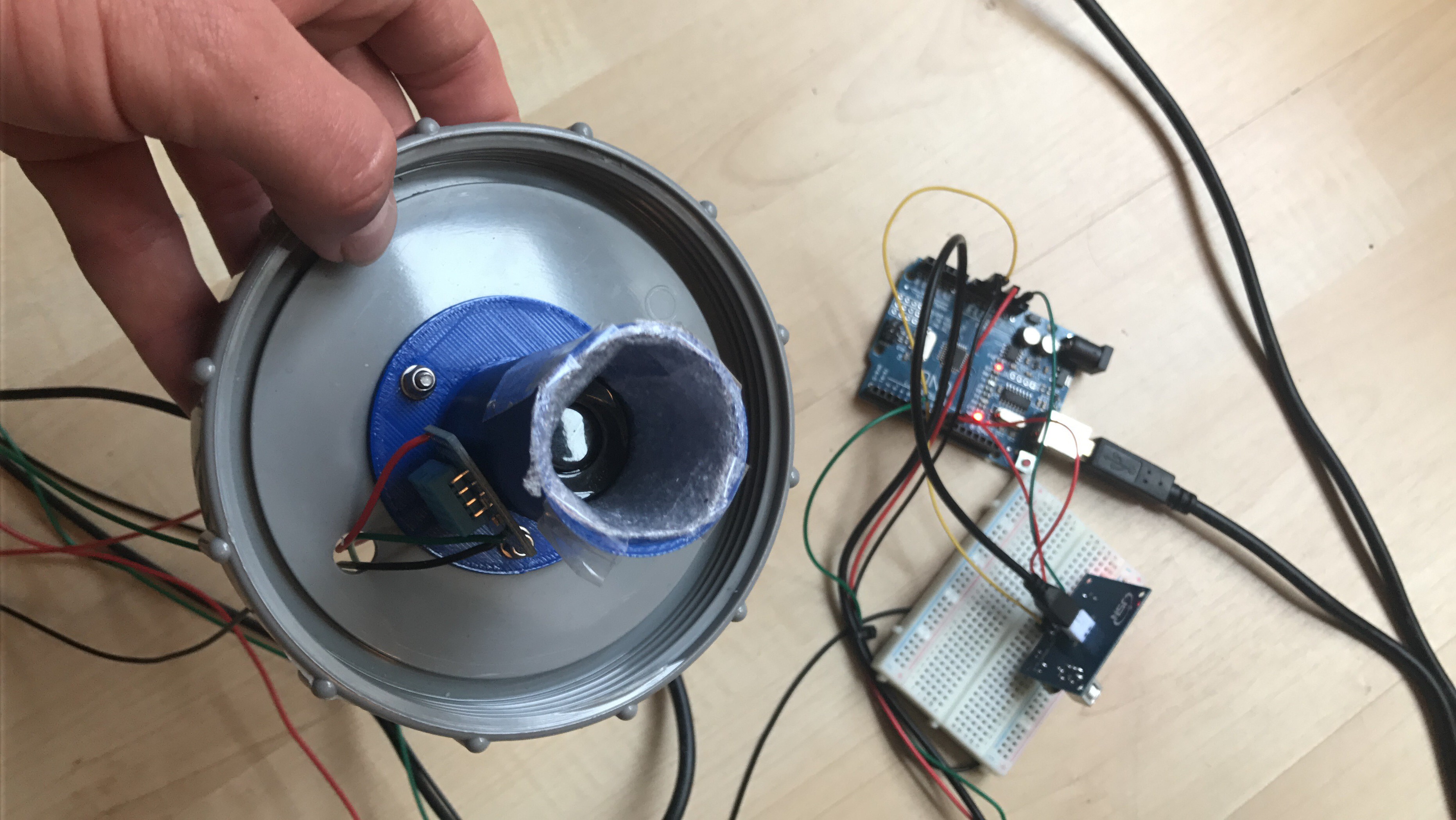 Nevertheless we would like to use as less material as possible, so we tried a second material, which was craft foam. This did not work at all. So we immediately tried a third one: felt. This turned out be the best material for our purposes. The size of the funnel does not matter. However, the possibility of accretion is a big disadvantage.
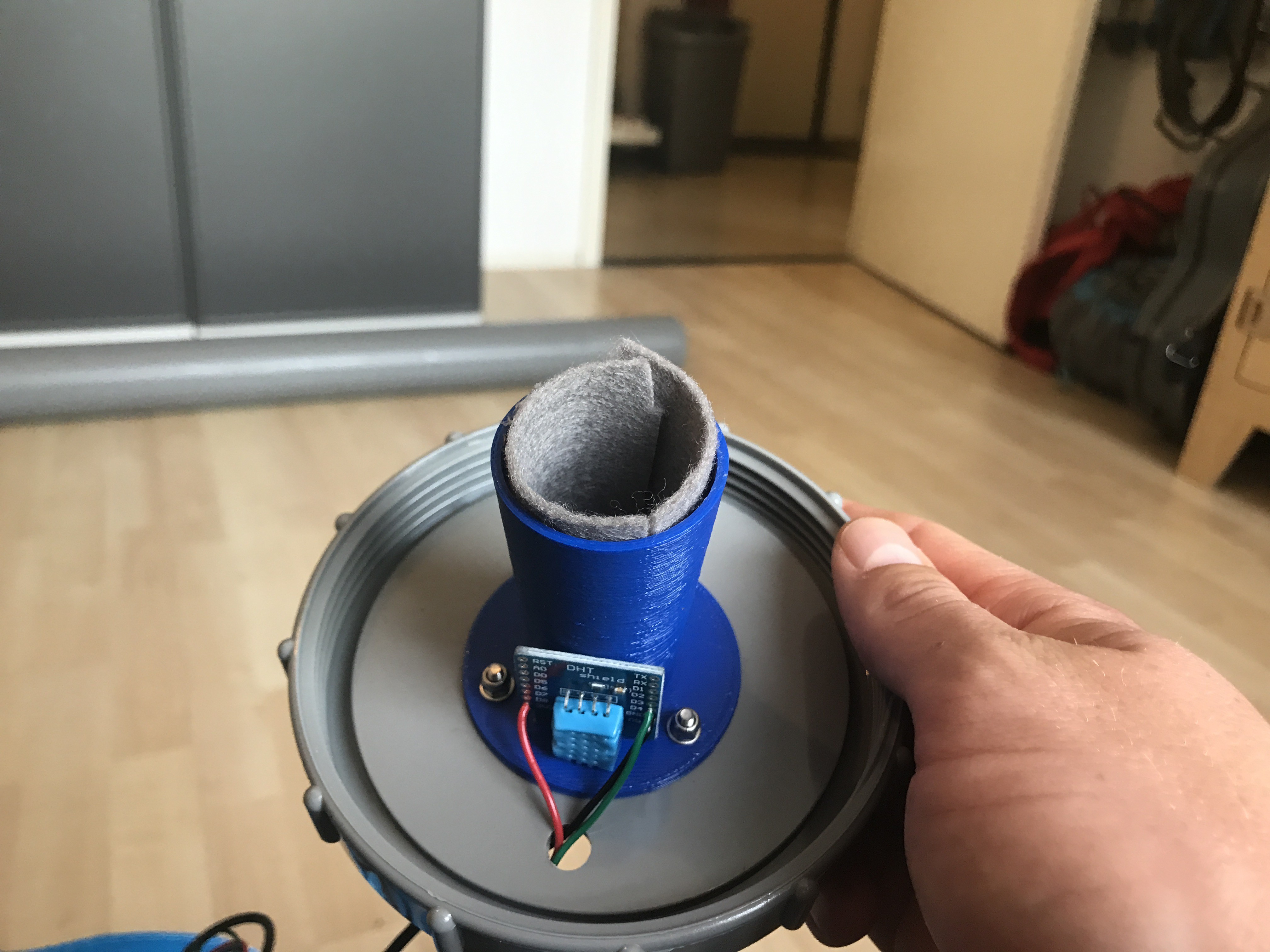
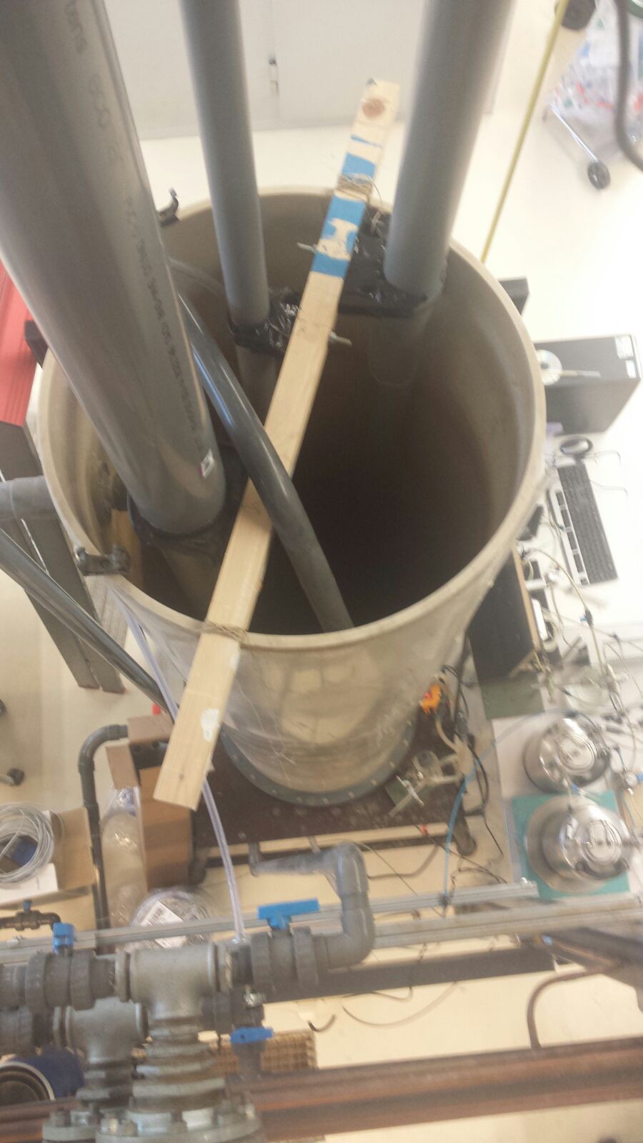
 Tomorrow (Wednesday the 3rd of May) we will have a tour through the laboratory and hopefully we can start with some of the experiments


 Ostapsky
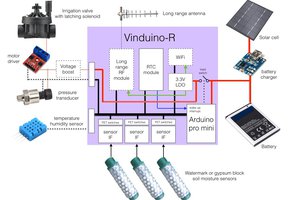
 Reinier van der Lee
 Claudio G. Hutte
 Florian Ellsäßer
A $4 NodeMCU can send data to a cloud spreadsheet or to an online graph via MQTT.
https://sites.google.com/site/nodemcu12e/