 Matt Moses
The RepKiln project aims to create a small, simple, inexpensive, and relatively safe and clean kiln/furnace/oven for melting aluminum and firing basic pottery. It is made by assembling homemade firebricks. The kiln is designed to produce more bricks of the type from which it is made, hence the "Rep" (for replication) in the name.
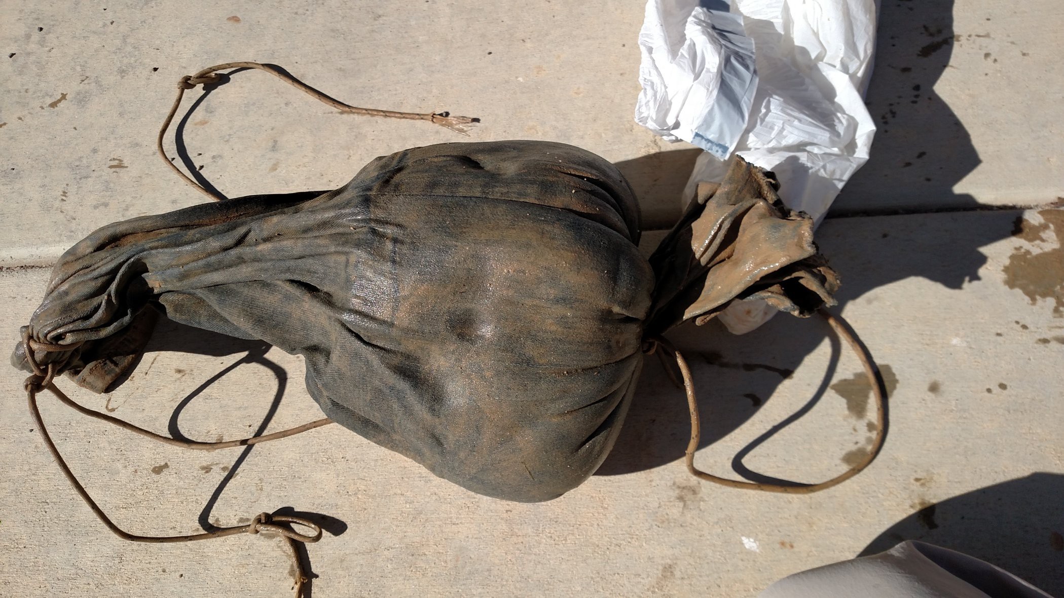
RepKiln got started as a spinoff of a completely different project: a backyard chicken coop. To make the coop, a lot of dirt had to be excavated to make a giant sandbox for the chickens to poop in. I live in a densely populated subdivision where the backyards are small and not all the neighbors are thrilled about chickens. Hence chicken poop management is important.
After building the chickens their fantastic sandbox, there was a lot of soil leftover. Due to the small yards this soil couldn't just be dumped off in a corner and forgotten about. So I hatched a scheme to process the soil and return/disperse it back into the yard. This process is described in detail in the build logs.
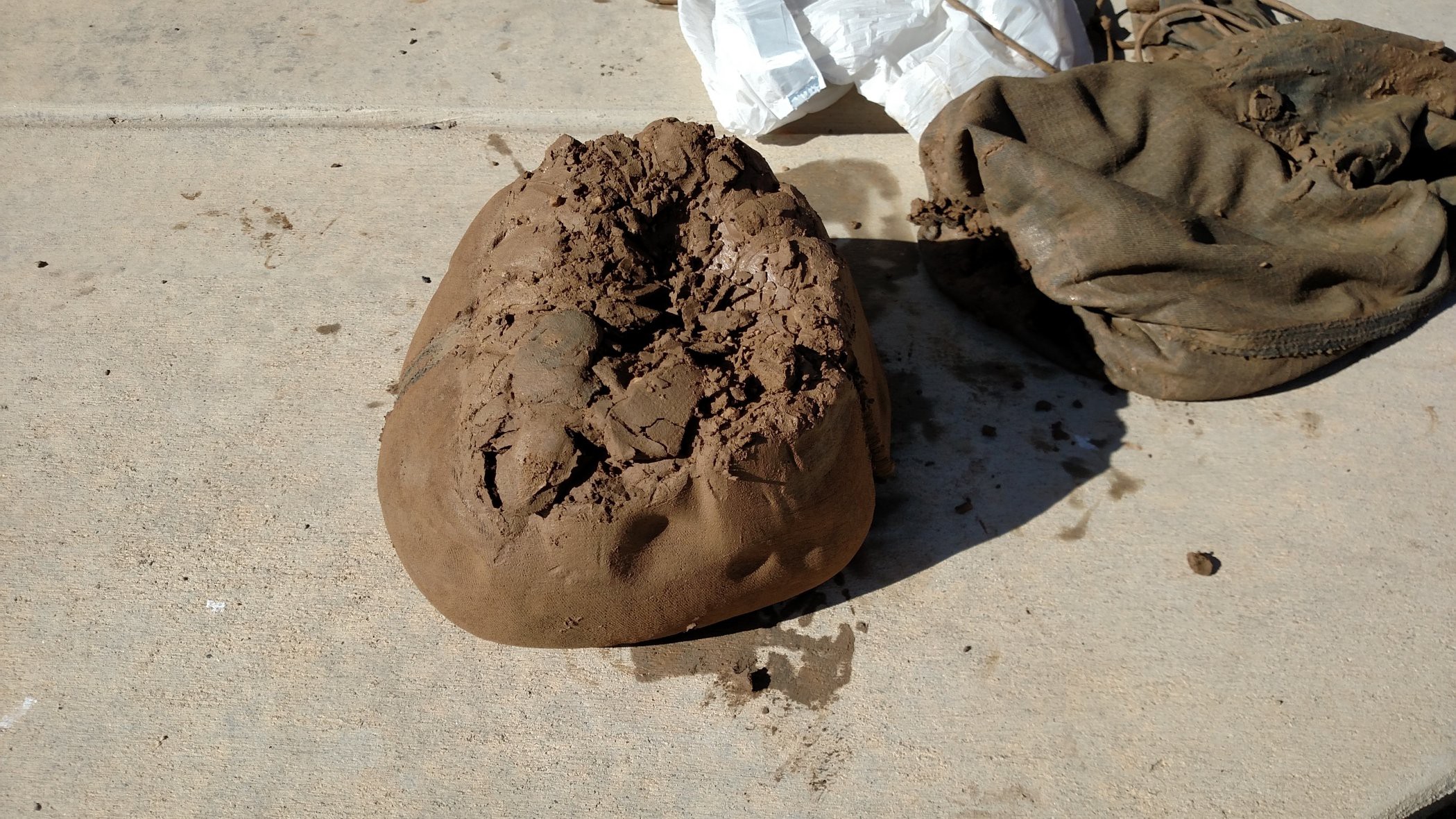
The soil is primarily very thick clay interspersed with rocks. So I ended up with a lot of natural clay that I wasn't sure what to do with. After watching Primitive Technology Guy on Youtube build a kiln out of dirt with his bare hands, I thought it might be fun to try something similar, although not quite so primitive.
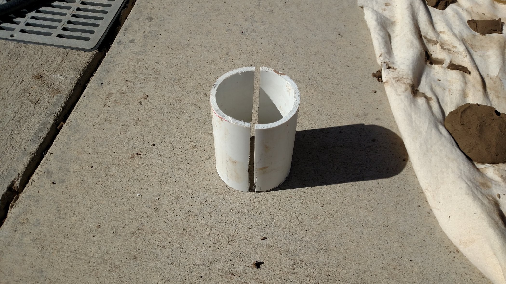
The idea is to process the soil into clay, process the clay into bricks, put the bricks together into an (electric) kiln, and use the kiln to do something useful - like fire pottery made from some of the rest of the clay (there's tons of it) or melt aluminum for casting. I hope that other people might want to make something similar to what I want, and maybe they might have similar building materials (e.g. dirt) and design constraints (e.g. 110 VAC @ 15 amps). If so, looking at my project might help them with theirs. I got a lot of ideas and inspiration for my project by looking at the work of others! I made an effort to credit this inspiration wherever possible, so these other projects are noted at various places in the project logs.
If you are interested in building something similar to my kiln, the best thing to do is to read the build logs in chronological order. The reasoning behind design decisions is discussed (well some of them anyway). There are also a number of design tools presented that might be useful also:
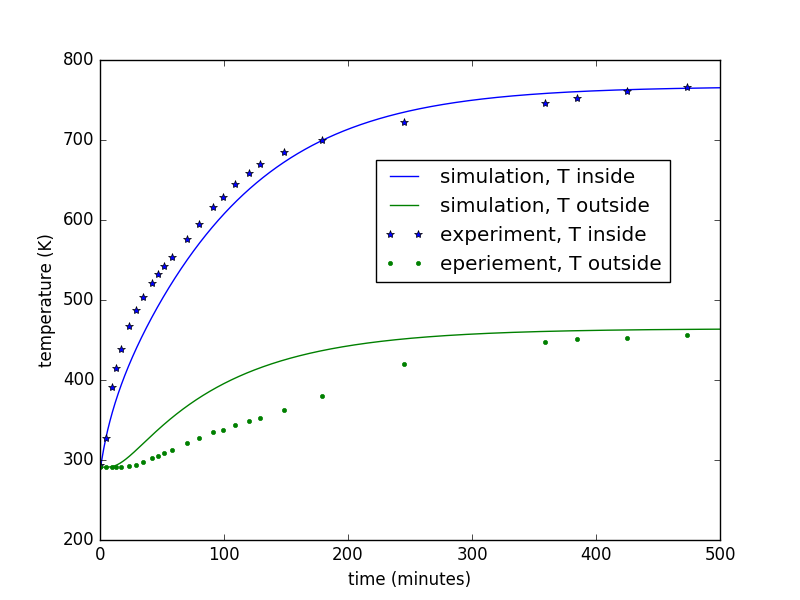
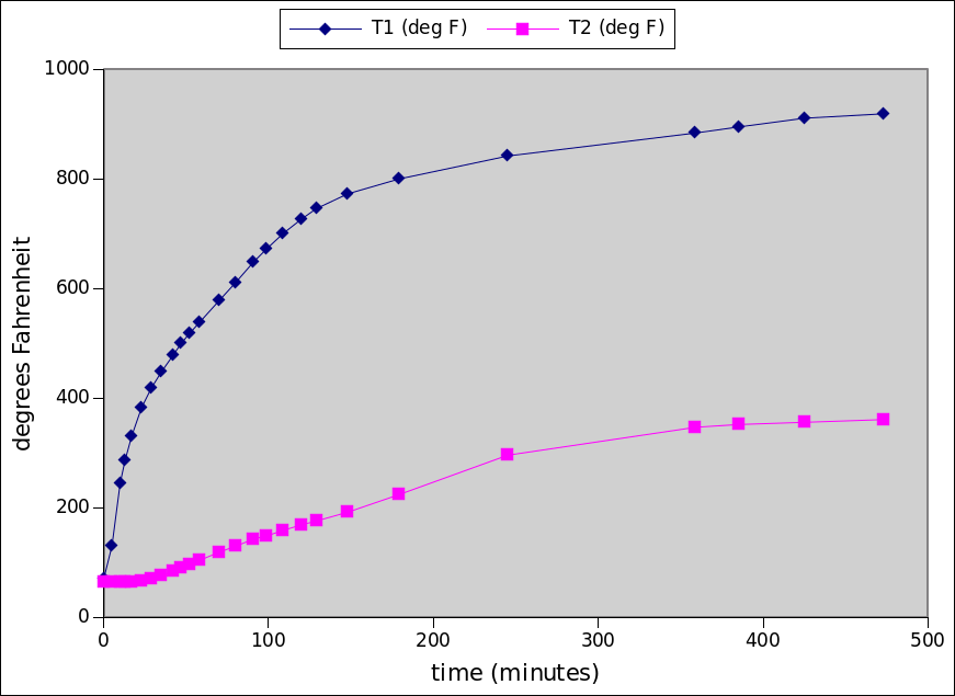
- simple calculations for basic heat transfer model
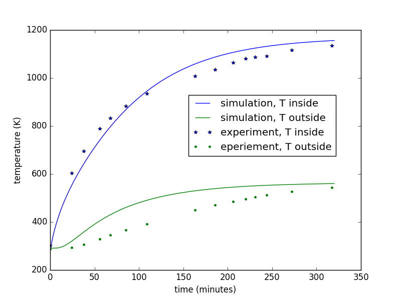
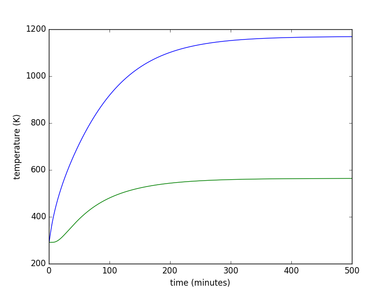
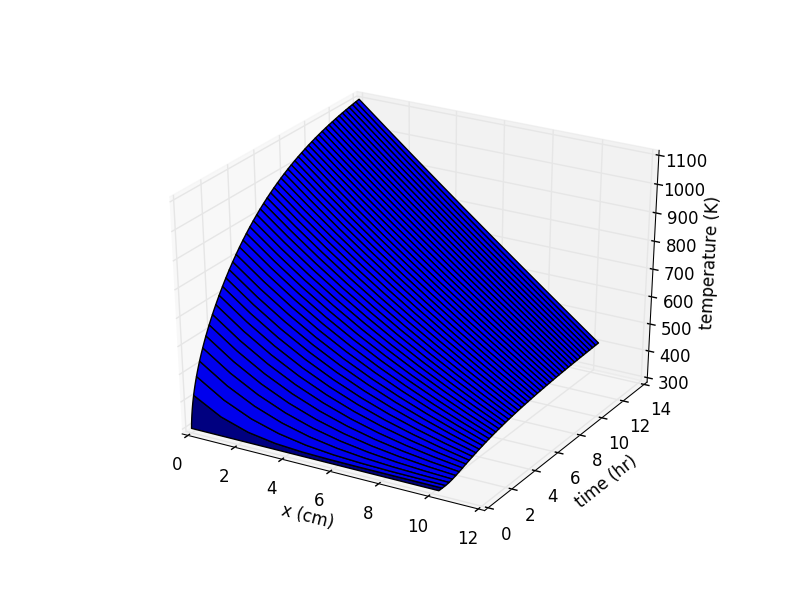
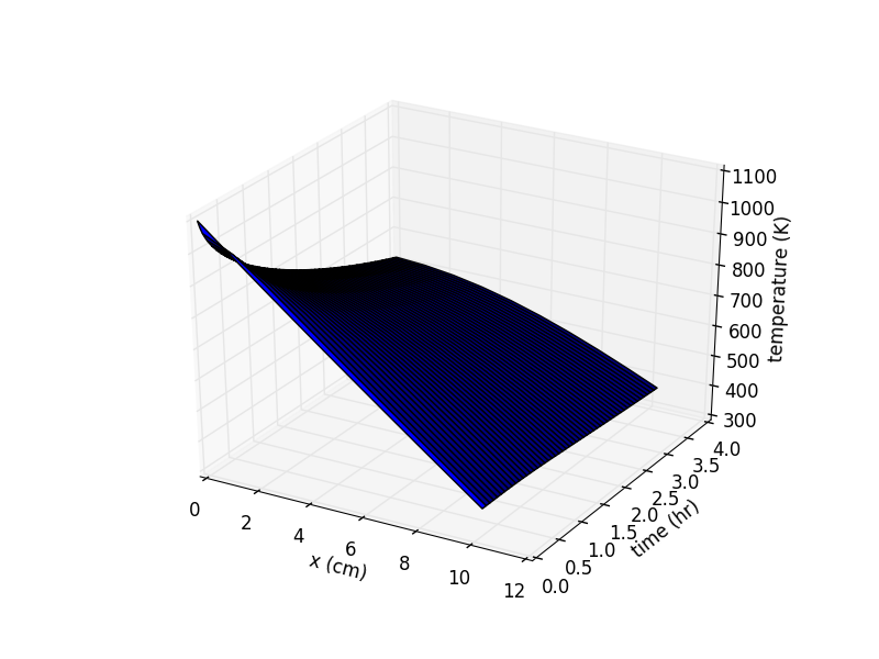
- slightly more complicated heat transfer model (with python code) for predicting kiln performace
- spreadsheets to help select kiln size, wall thickness, wall thermal properties, heater power
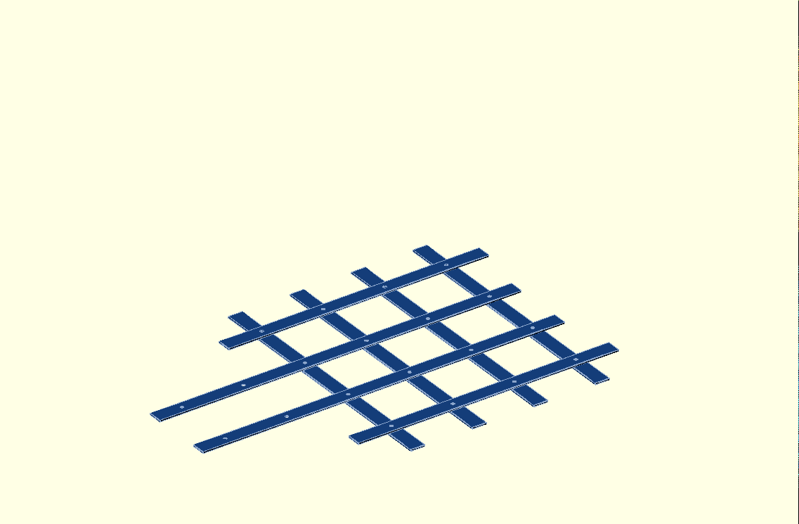
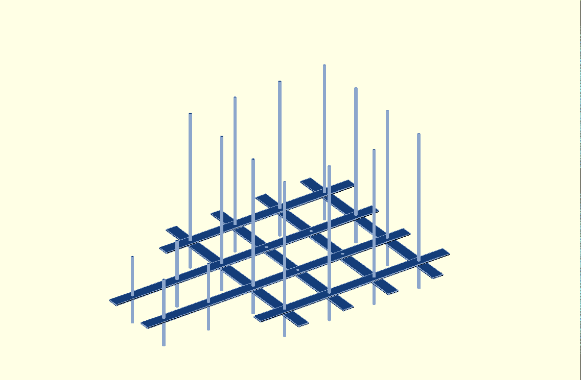
- OpenSCAD model of the mechanical layout of the kiln
- discussion of tips and techniques for various tasks: molding bricks, winding heater coils
Building your own kiln isn't exactly a new kind of project (people have been doing this for a few thousand years). But it's always possible to put a new twist on an old idea. Some of the ideas here might be useful to people in developing or remote areas, where off-the-shelf kilns and off-the-shelf materials (e.g. firebricks) might not be available. Maybe the methods for making clay from dirt, all while recycling the water used for processing, might be useful for bootstrapping an industrial base on some place like Mars (or Taos).
Repositories
The git repo for RepKiln is here: https://github.com/mattmoses/RepKiln
Licenses
Unless otherwise noted, all images published in this project are the work of the author (Matt Moses). Photos, drawings, and spreasheets are released under Creative Commons CC-BY-SA.
OpenSCAD files and python files are released under GPL v3.
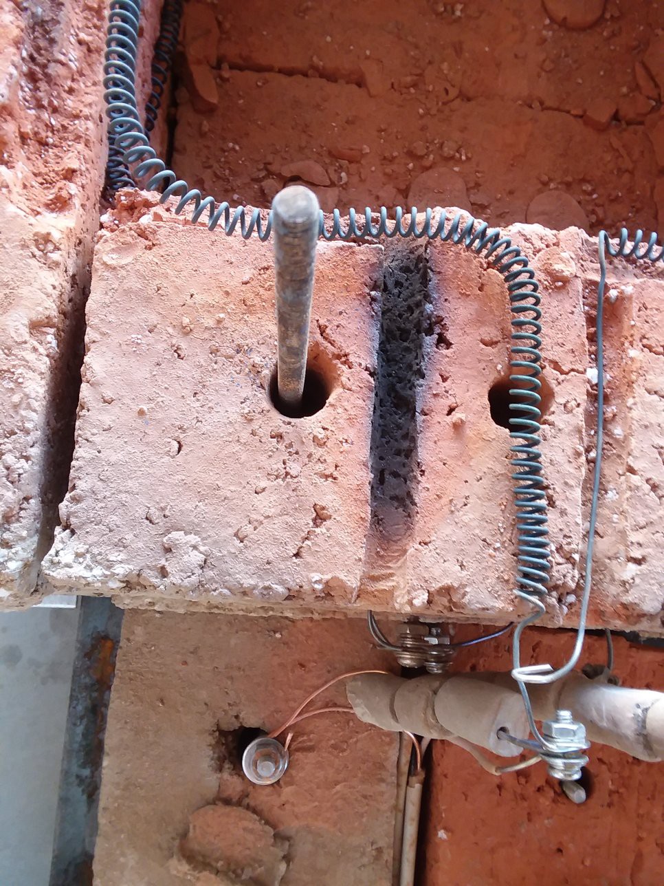
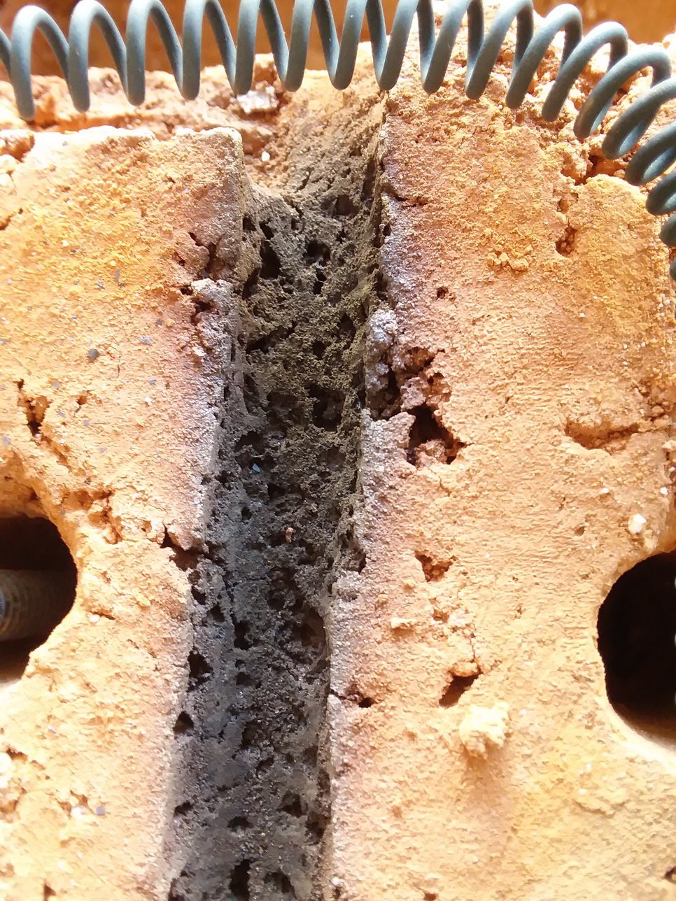
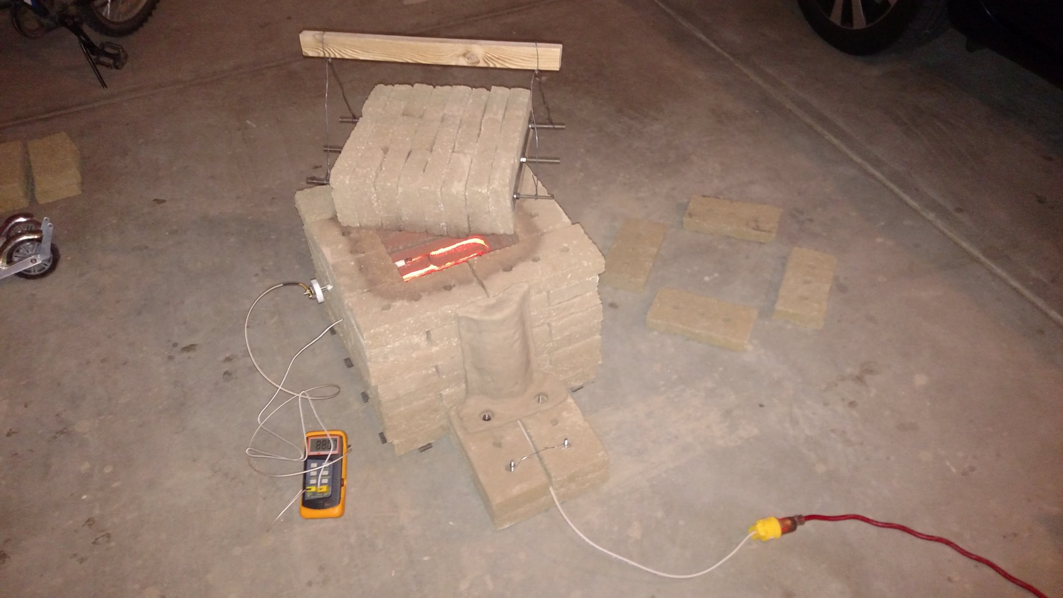
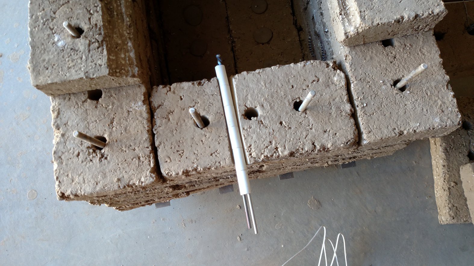
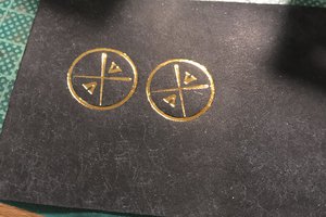
 After firing, the clay objects turned a deep red. The red color apparently indicates a high iron content in the clay, which according to some of the readers, can cause problems for the nichrome heater wire. So I may need to think about ways to insulate the nichrome from the bricks for long term use...
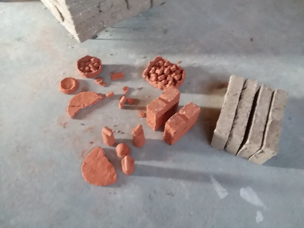 As an aside, the extra heater wiring was installed with the help of some clay bead insulators:
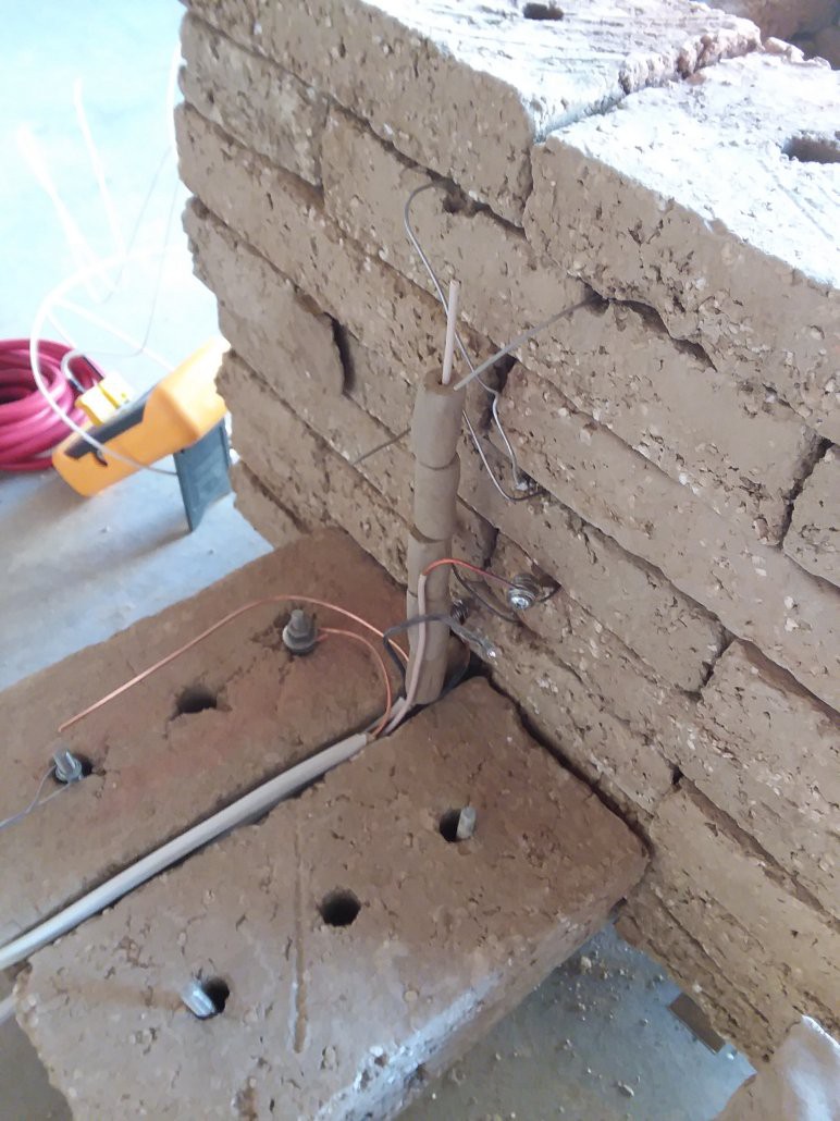
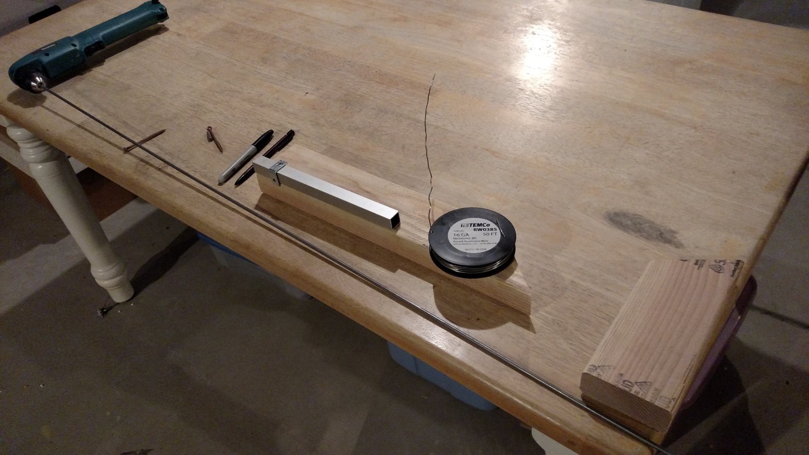
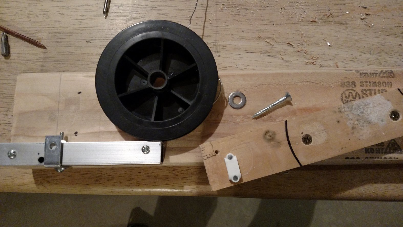
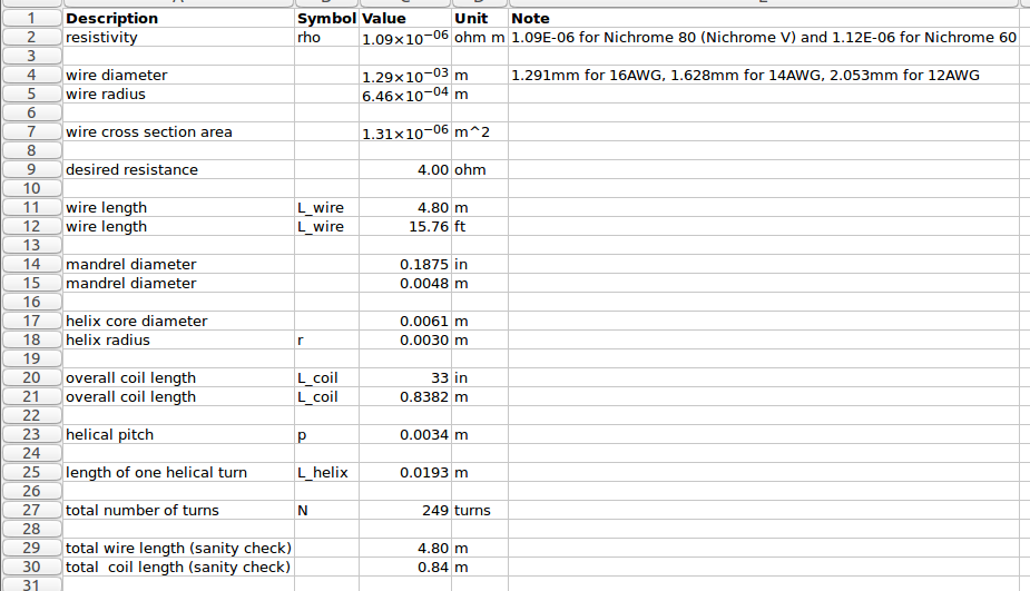
 There are about 20 turns per inch, so we need to wind 250/20 = 12.5 inches of tightly wound coil. This will then get stretched out for the final installation in the kiln.
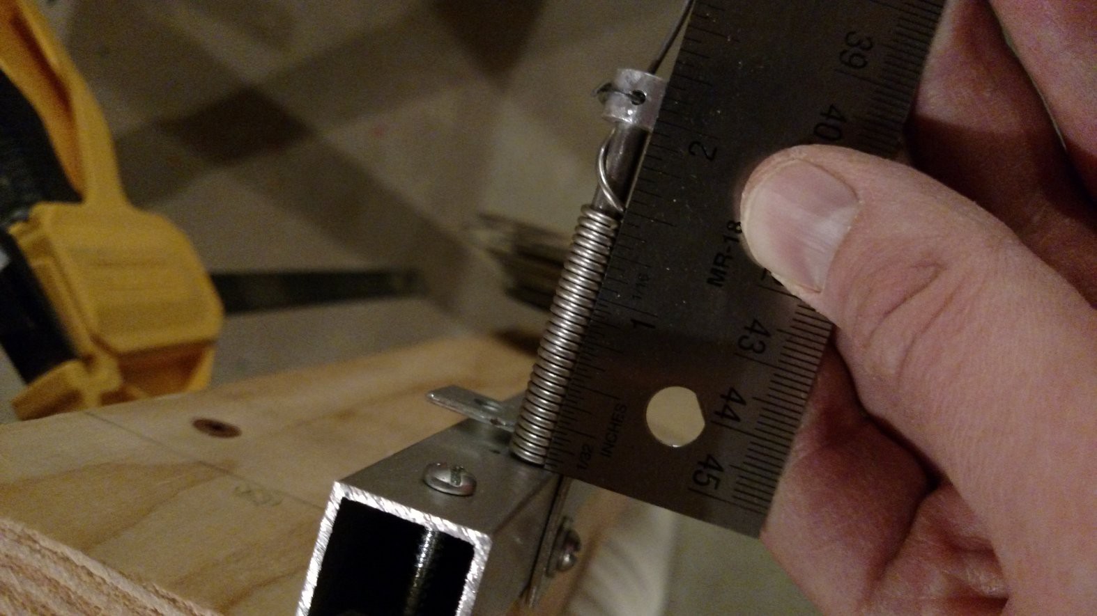 The first coil was a little longer than 12.5, so the second coil turned out a little shorter:
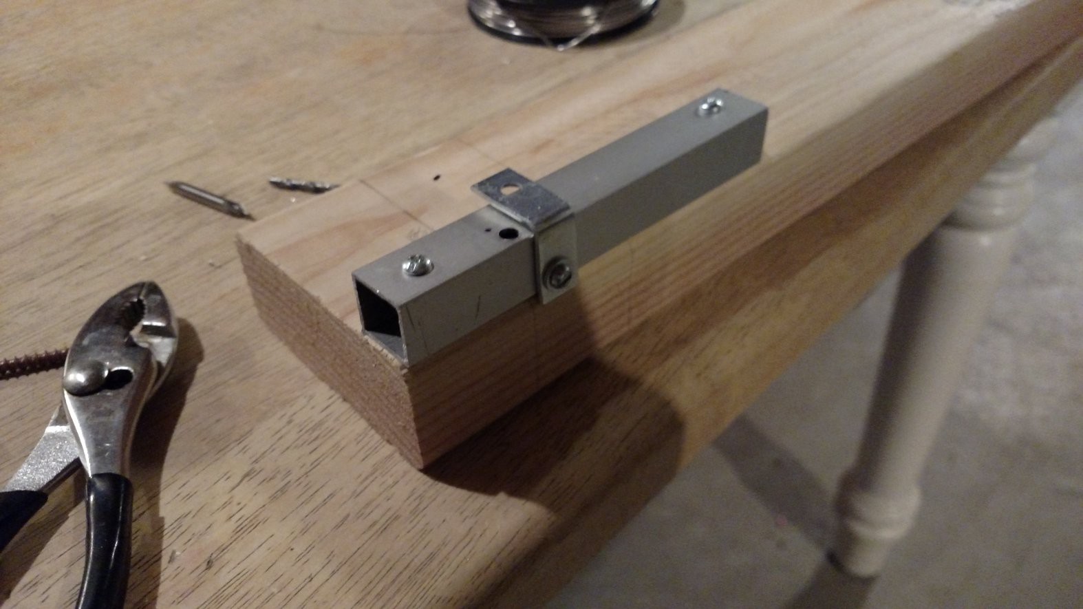
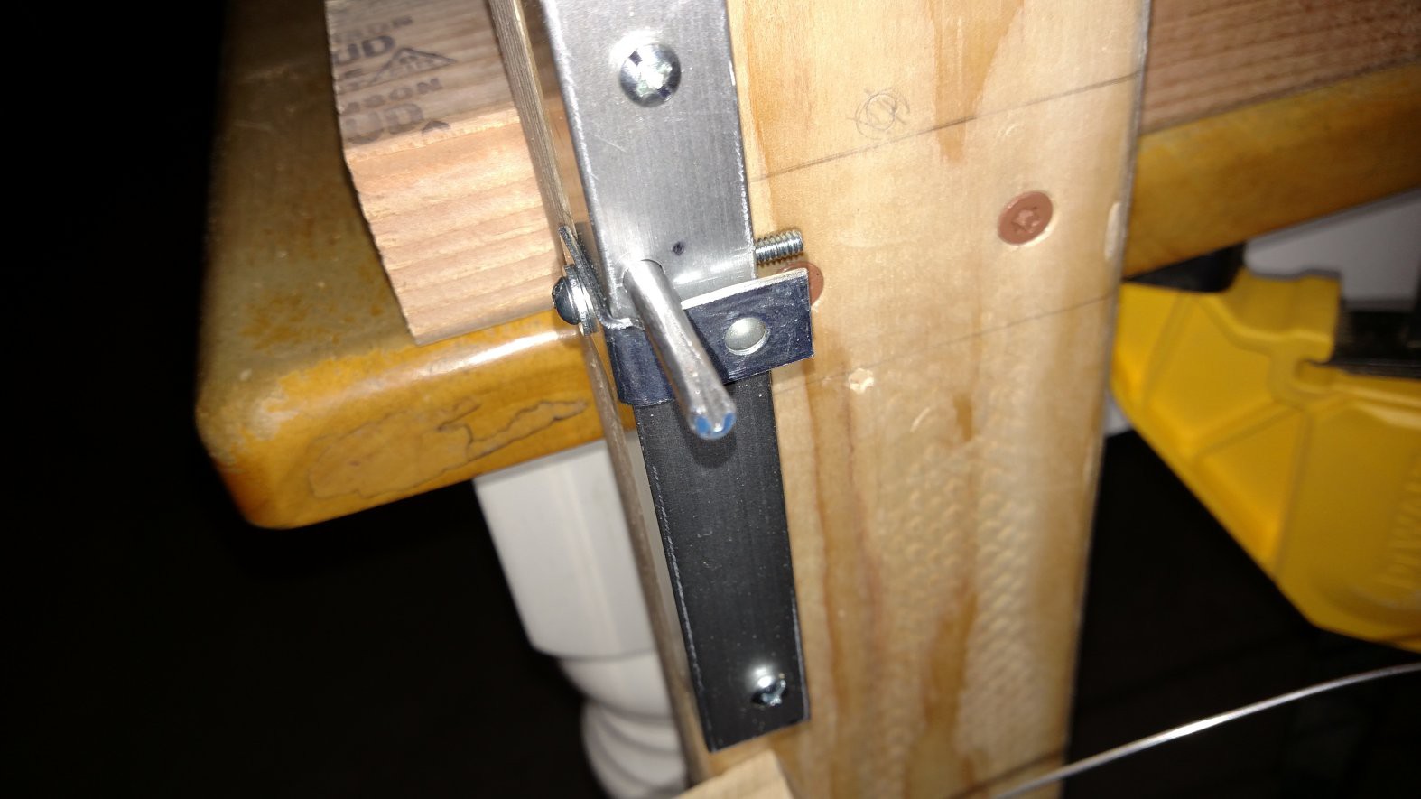
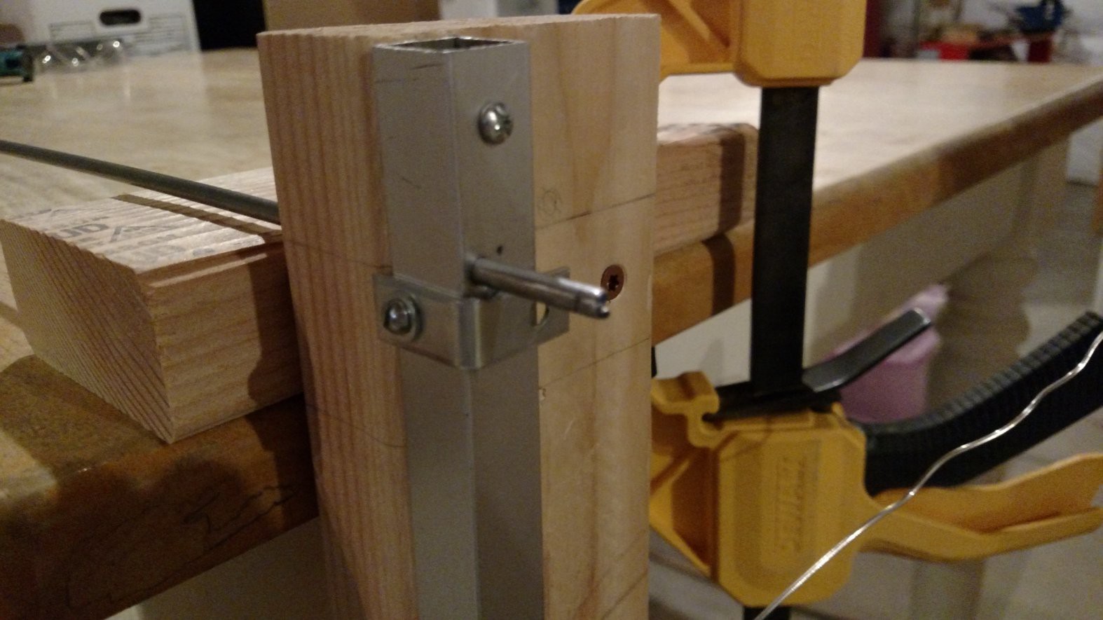
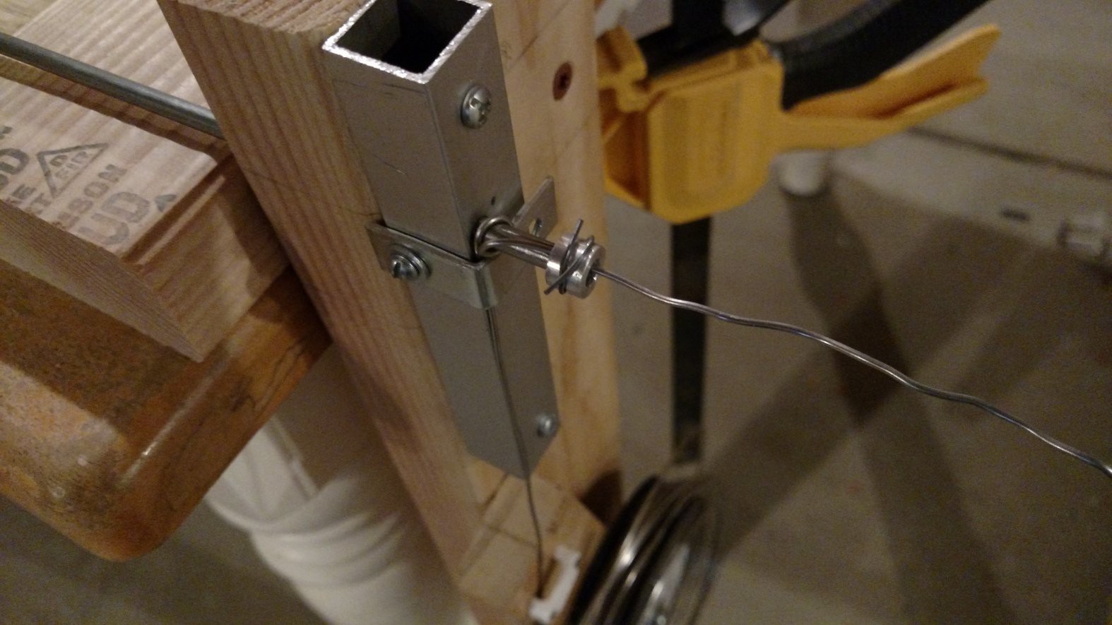
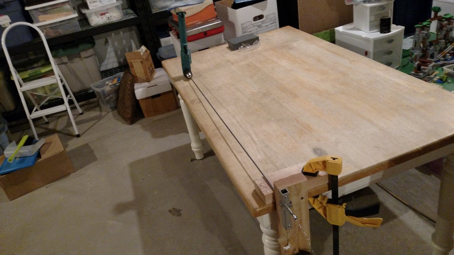
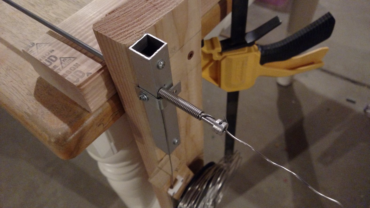
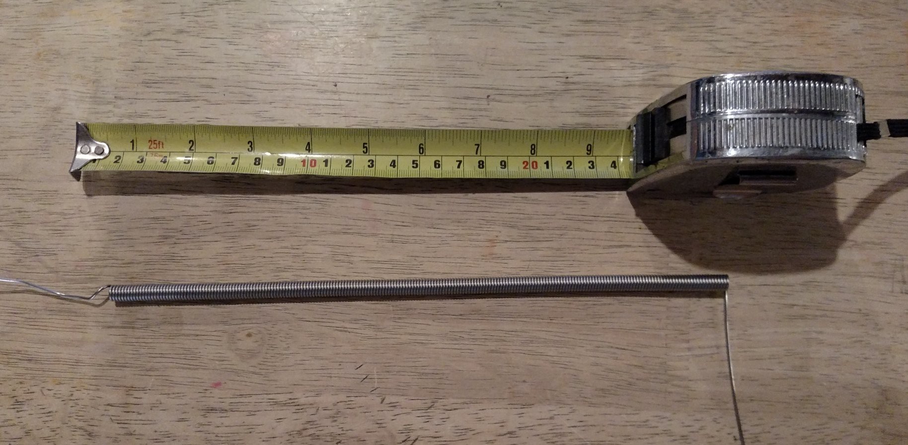 It's easiest to stretch out the coil by clamping one end in a vice and then (carefully) pulling the other end slowly and steadily with pair of pliers.
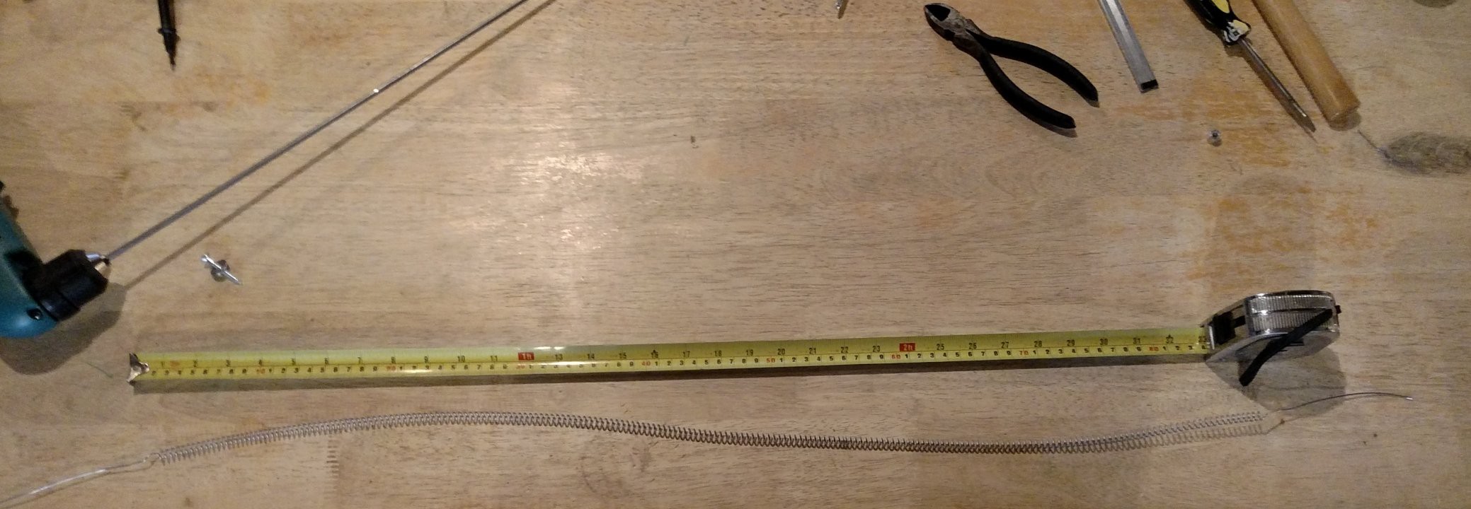
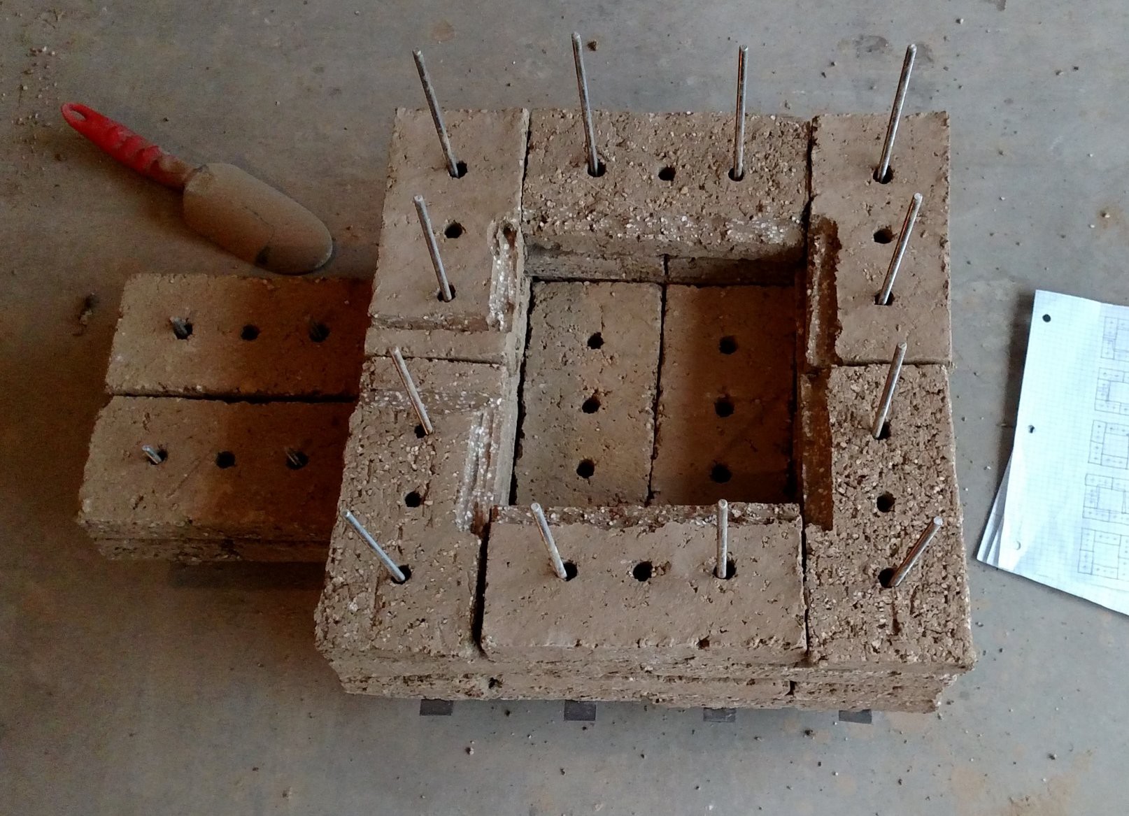
 Getting started...
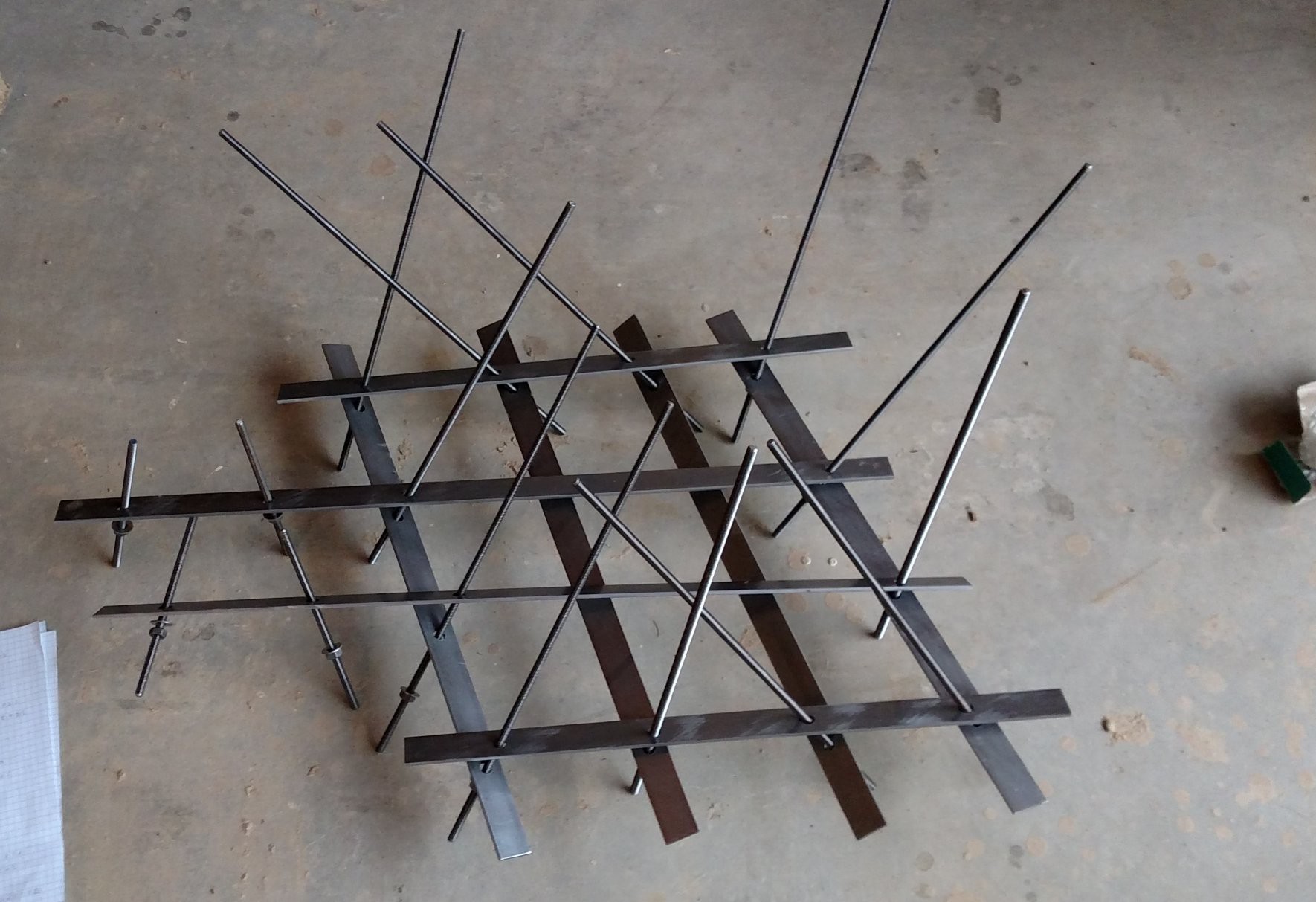 A real spaghetti mess
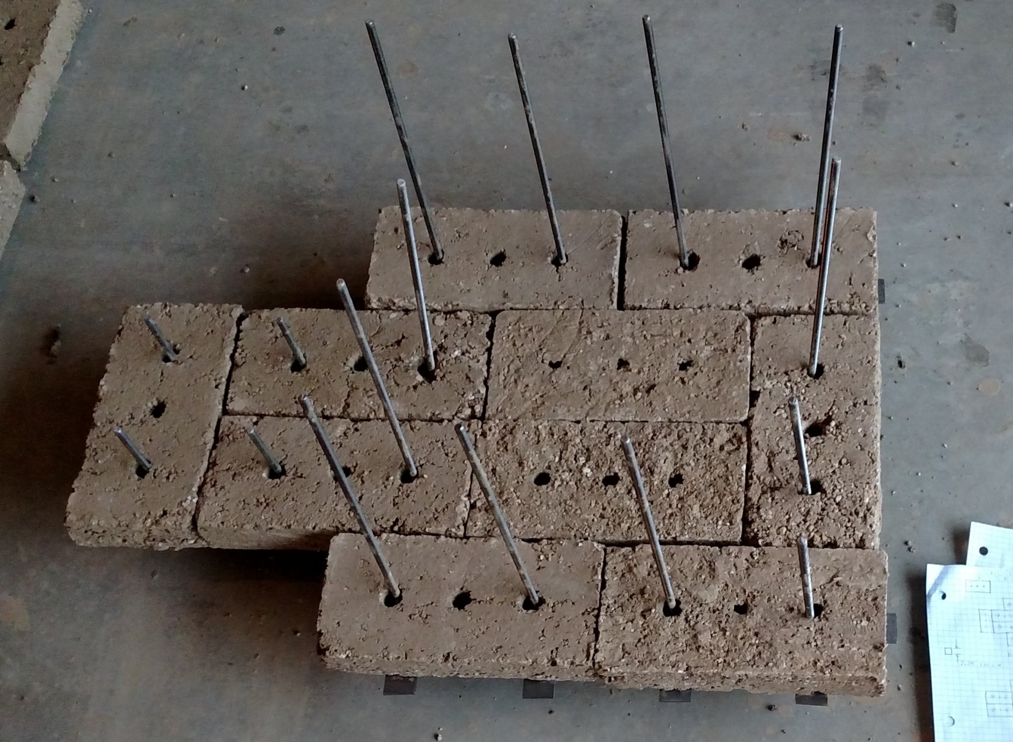
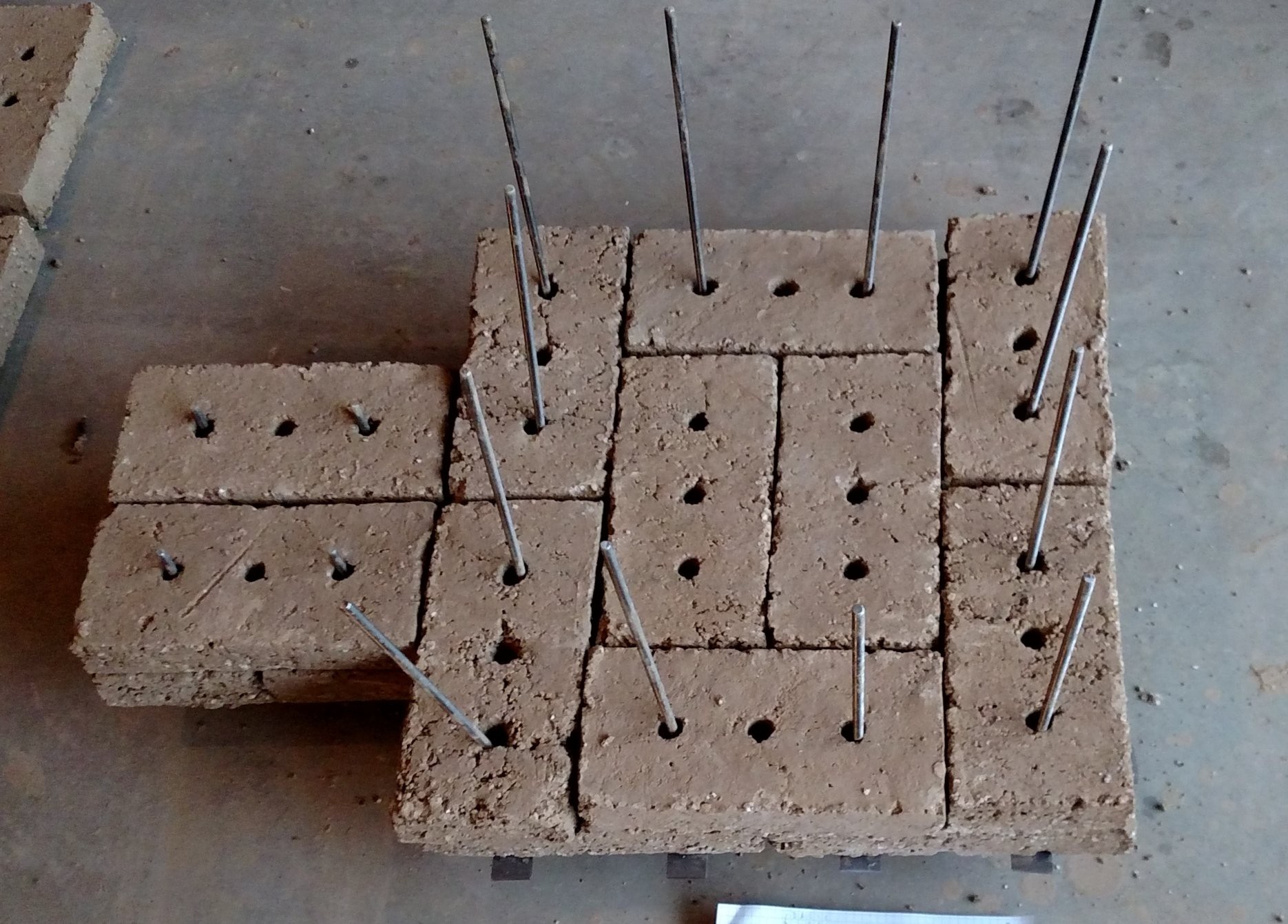
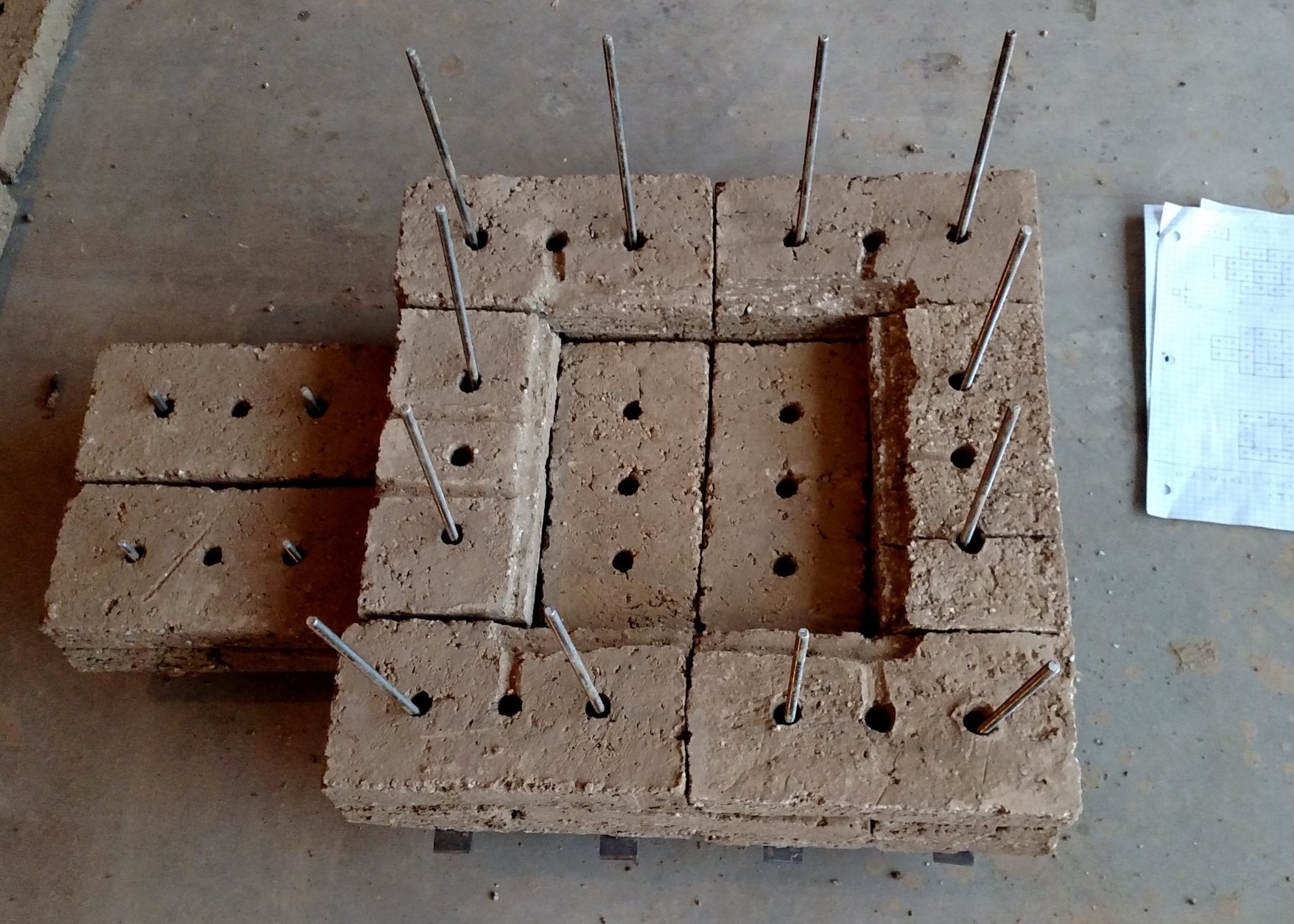
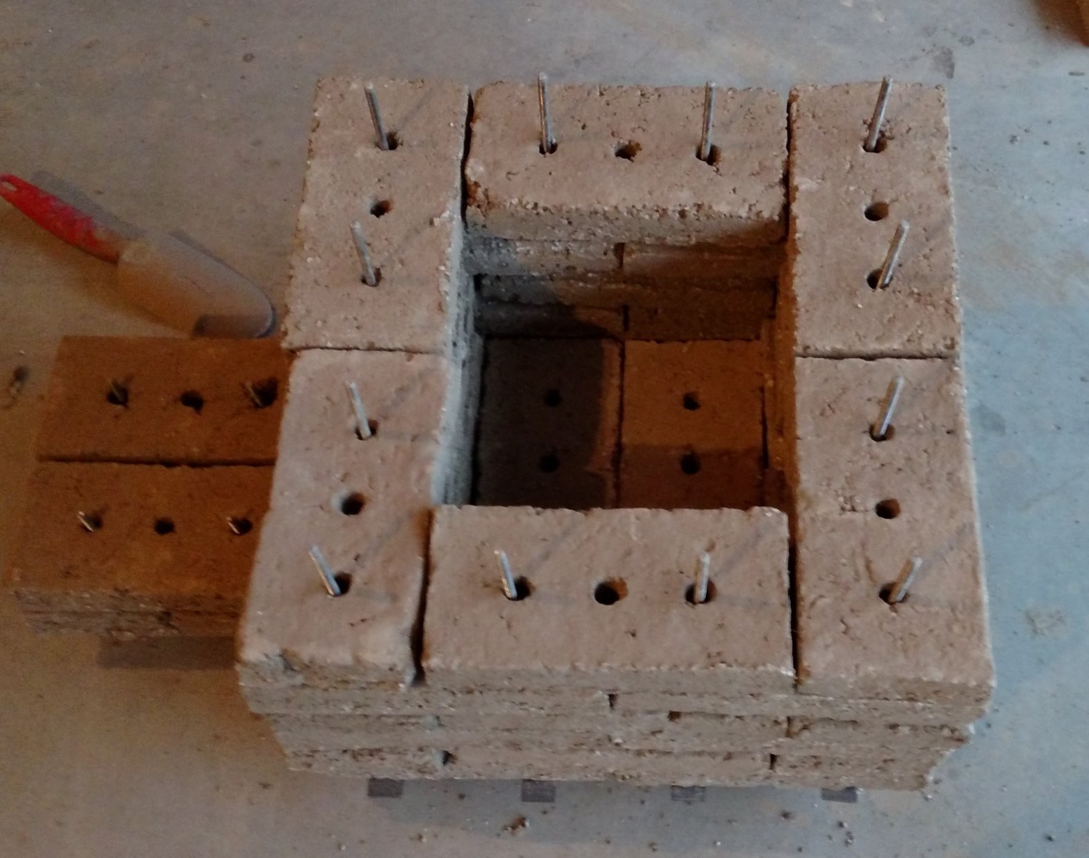
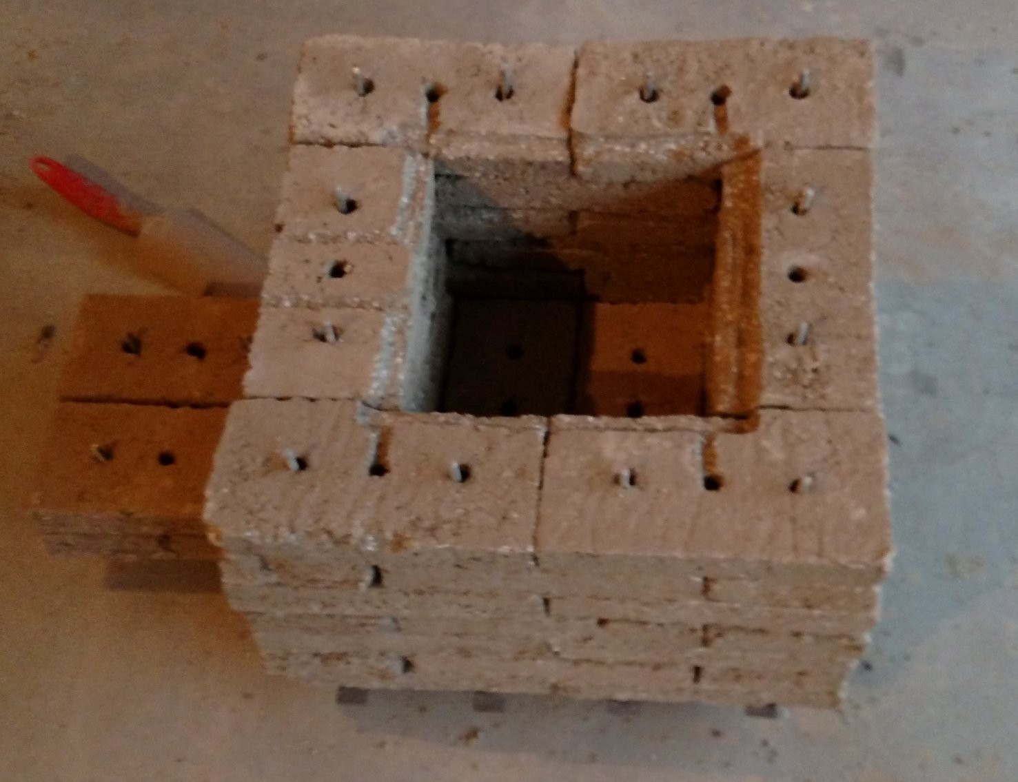
 Brick layer four
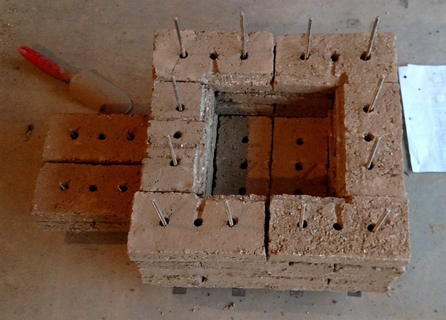
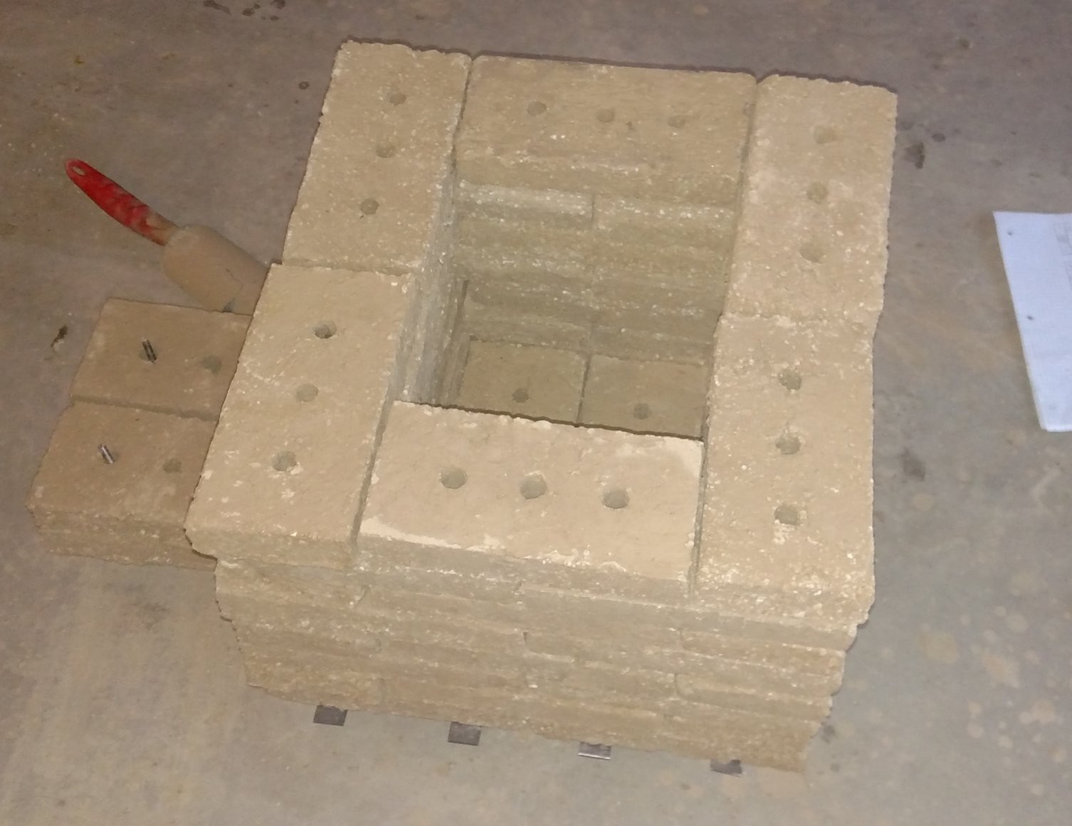
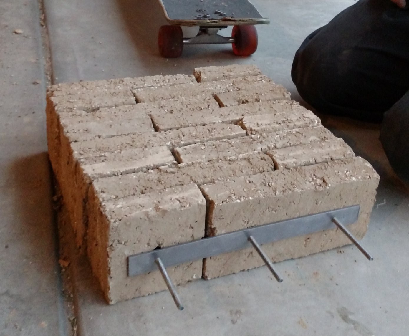 Lid
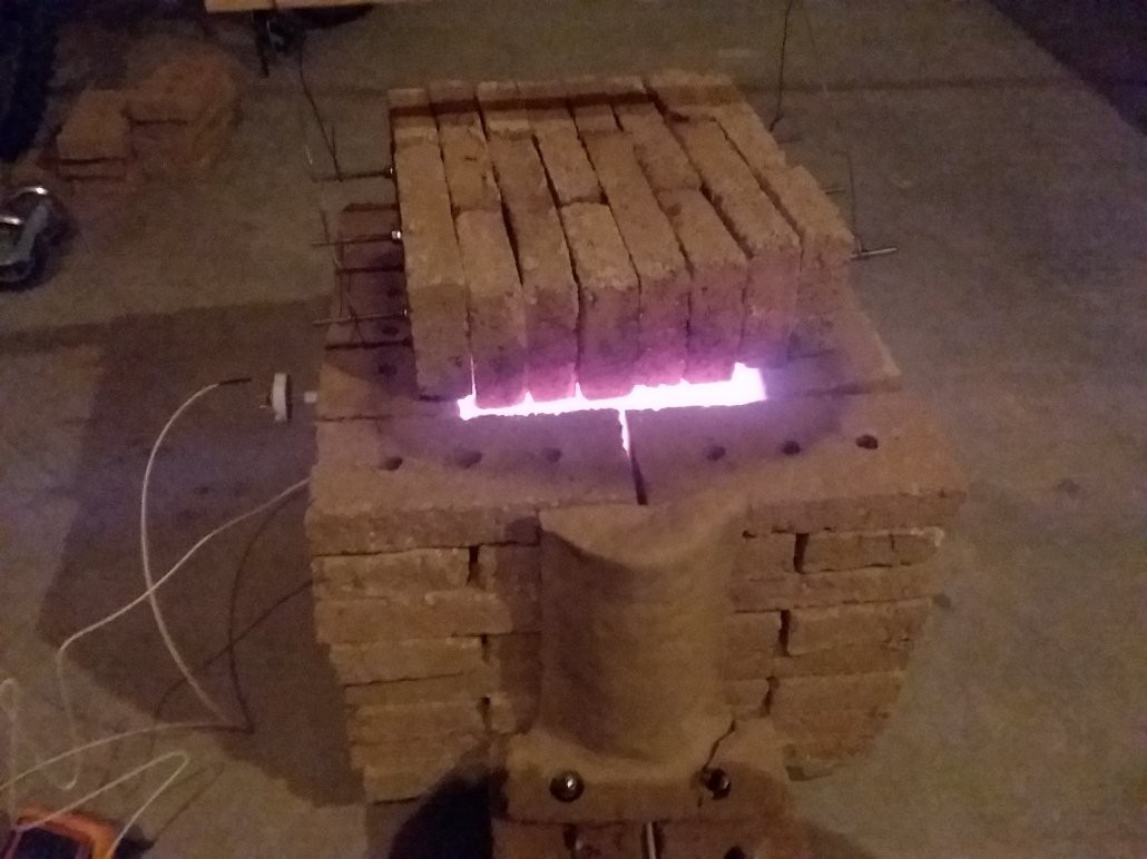
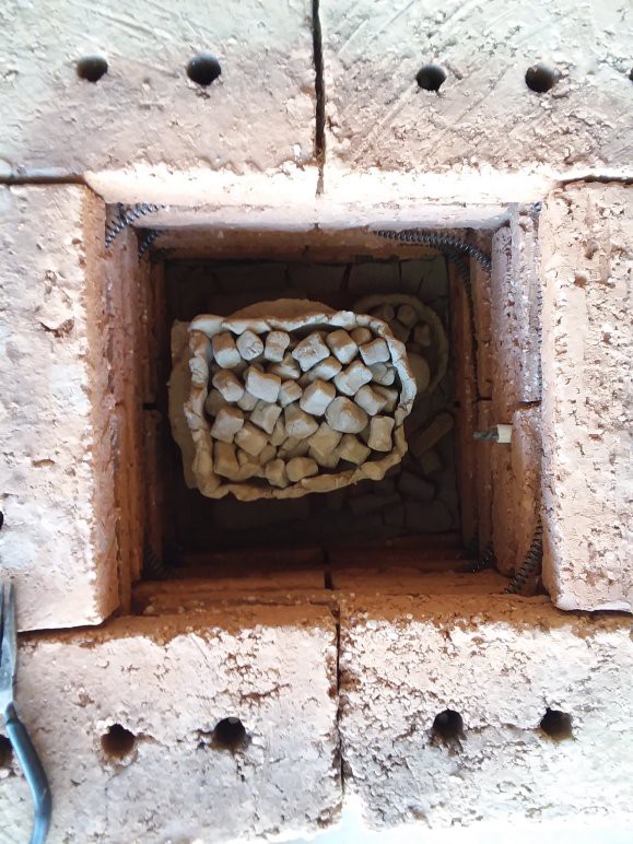
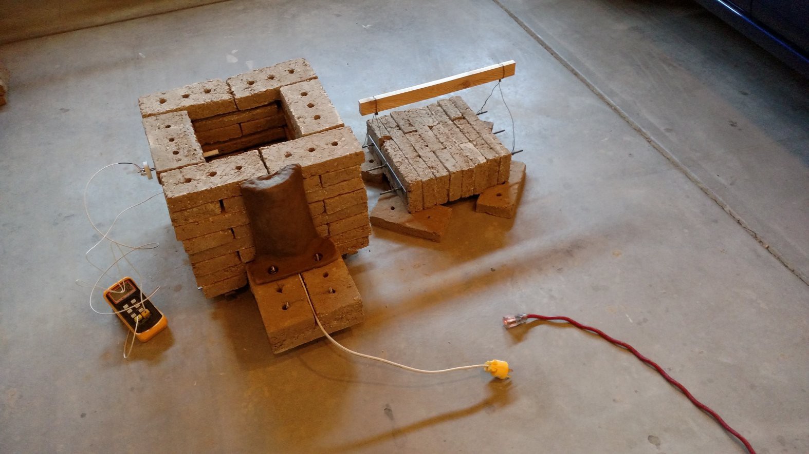
Lid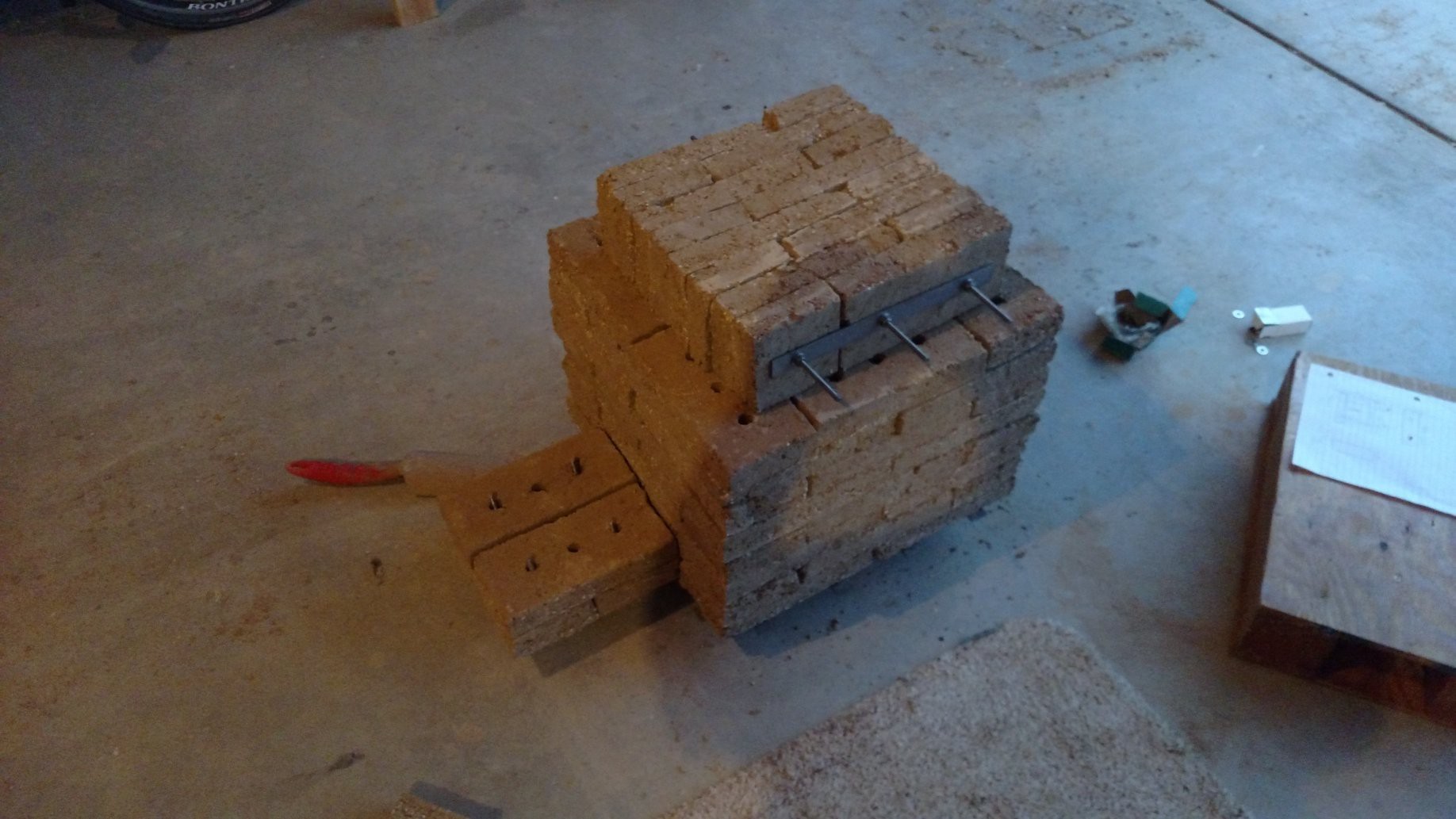 Fitupt Test Complete!
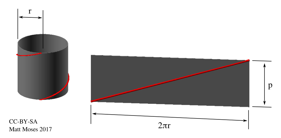
 So the pitch is 3.4mm (0.134 inches). It should work out fine to wind this by hand on the lathe. Stay tuned for that in a later update!
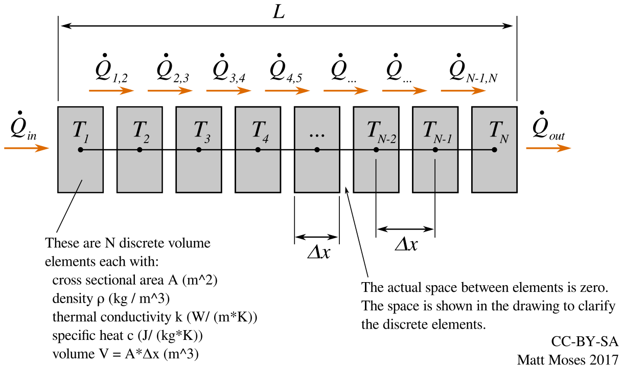


 vincentmakes
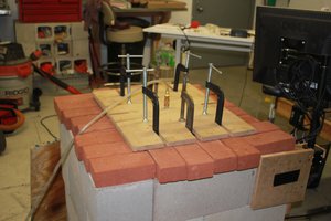
 Michael Barton-Sweeney
 xdylanm
 zackf69
There’s a lot of gap between the bricks. Bye bye heat. Do you have any clay mixture left you could use as a mortar? If you do I’d recommend a long slow firing after the mortar had a chance to dry. Or use a high temp mineral wool to insulate it and/or enclose it in a steel box.
Looking good!