 Chris
ChrisOverview:
Here a short overview about the techniques and chips used in this project:
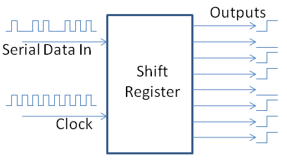
- I used an arduino and shift registers to control the 192 LEDs ( the popular 74HC595 )
- Shift registers can't handle the current of 8 bright LEDs so a Darlington Transistor Array was connected after the SRs ( ULN2803A )
- I did not want to solder 192 pre-resistors and I wanted to have the option to change the resistance for each color later on so I soldered two DIP sockets in parallel after the darlington transistor array. Those sockets would be populated with the according Bourns Resistor Networks. This way I could switch resistors on the fly.
- I used multiplexing. That means each of the four 4x4 layers is powered one after another. This way I only needed to control 4x4 = 16 RGB Leds (48 single LEDs) with the shift registers. Each layers anodes were switched with F9Z34N MOSFETs
- I used 5-Bit Angle Modulation to dimm the LEDs. It made the code a little more complex but there is no flickering now when fading from one color to another.
- The Arduino is not soldered but plugged into a socket. This is because I want to add bluetooth connectability later. Once I got the bluetooth stuff figured out, I just plug a small PCB between the socket and the arduino (Whohoo extendable ;)
- The PCB was DIY with the toner transfer method
The code and the circuit board layout can be found on GitHub: https://github.com/cgrossde/RGB-Led-Cube
This was my first time using eagle and designing a board, so don't expect it to be perfect. Also beware that the schematics miss some minor but important changes which were applied after the board was etched:
- Added a diode for reverse polarity protection!!
- Added a switch so the cube can be turned off
- Power the Arduino only if the switch is on (e.g. connect 5V and GND after the switch with the Arduino)
- This also makes sure that the Arduino does not try to power the whole circuit while programming it over USB
What needs to be done:
In order to connect the Cube to the "Internet of Things" and use it as a fancy representation of my mail box, or other stuff I need to add a bluetooth module to the design. I had extendability in mind when designing the cube and did not solder the arduino onto the board. Instead I used a socket to plug it in. Once I got the bluetooth magic figured out, I will create a small PCB with the bluetooth module and plug it between the socket and the Arduino. After that I will use my RPi as a middleman to connect it to the internet.


 Ben Patterson
 James Wilson
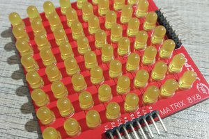
 ElectronicABC
 Dirk-WIllem van Gulik