 Tron9000
here things will go
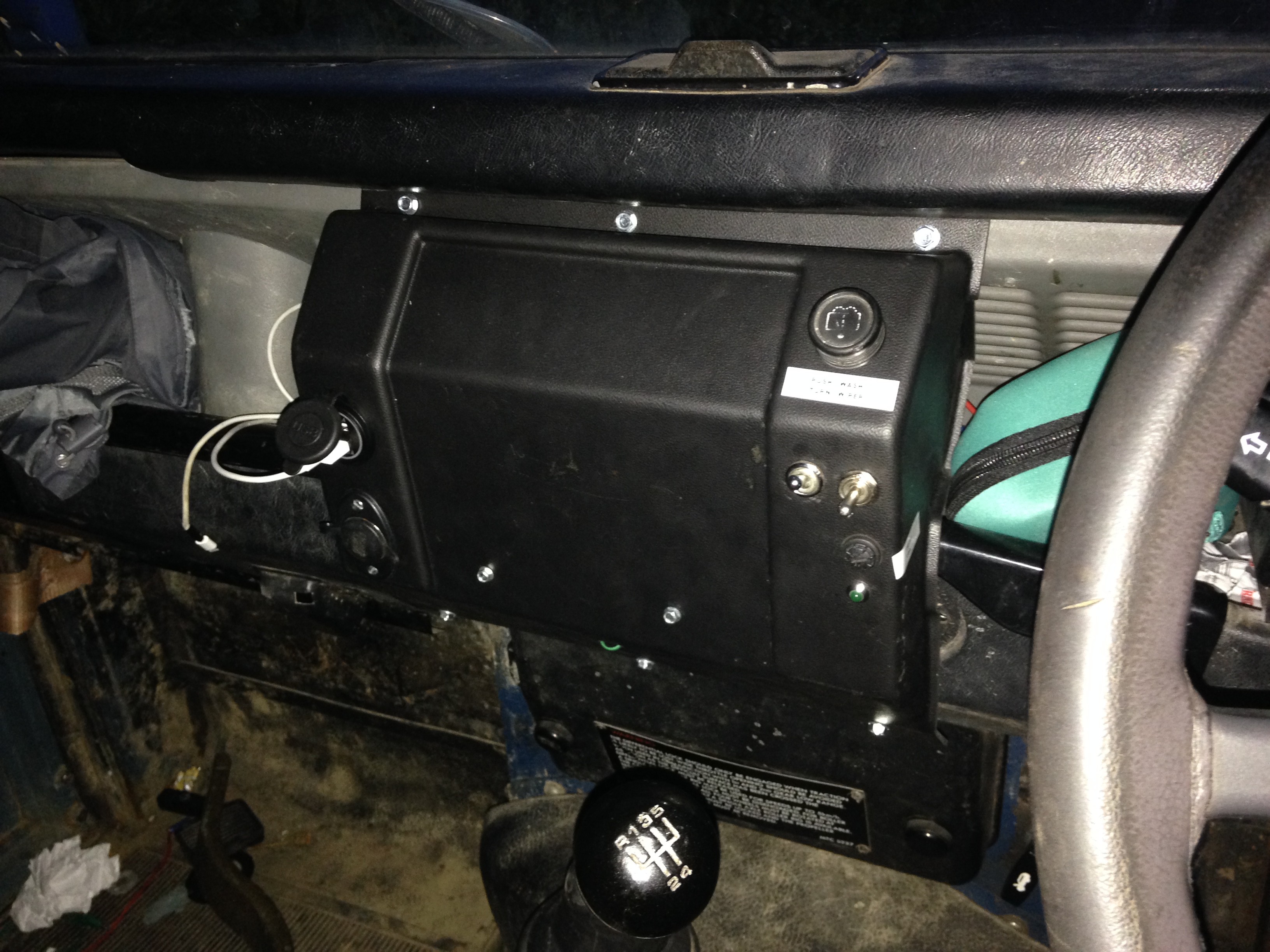
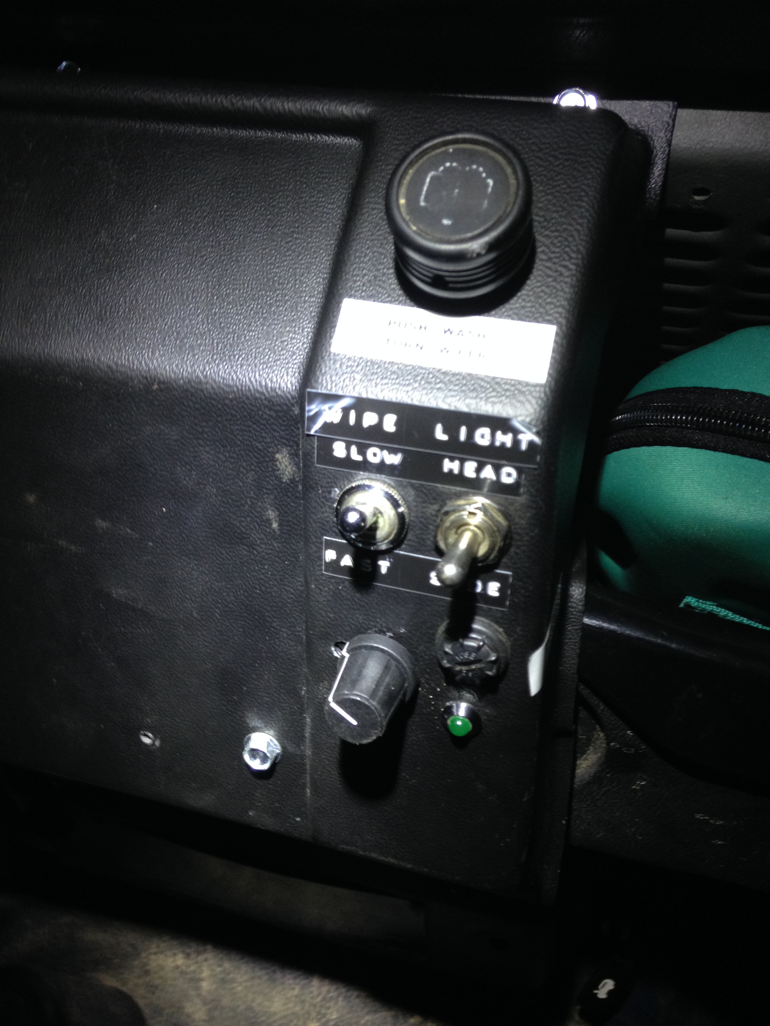
Recently the switch that controls the screen wash jets stopped working, so saw an opportunity to improve my wiper system whilst I am trying to get a replacement wiper control system fitted.I fitted a new centre console on the dash to accommodate the new switches and fitted some existing accessories to it:
Finding stuff out
The existing wiper system is controlled by a stork on the steering column. There are 4 positions:
- Centre - off
- Momentary position which you push down on the stork, which allows one single wipe of the screen
- Push up one position to engage a slow constant wiping motion
- Push up again for a fast constant wiping motion
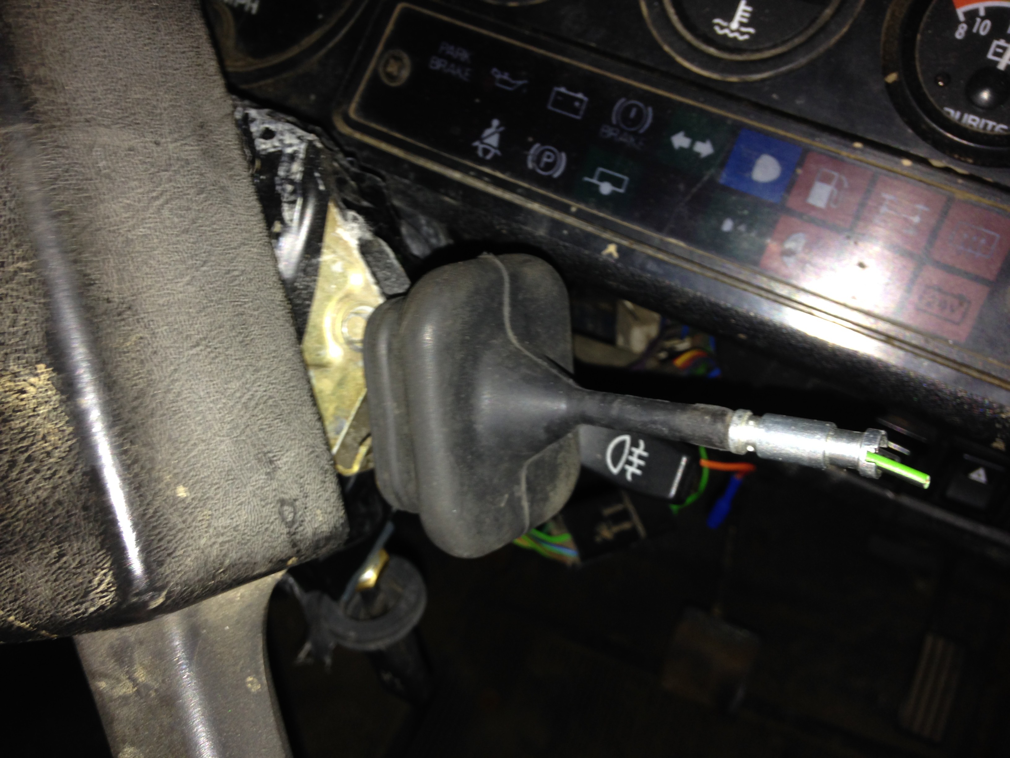
Though you can barely tell the difference between the first and second positions. The metal barrel at the end of the stork should have a plastic fitting over it, and shorts out the Green-Black wire to it, thus operating the pump in the screen wash bottle.
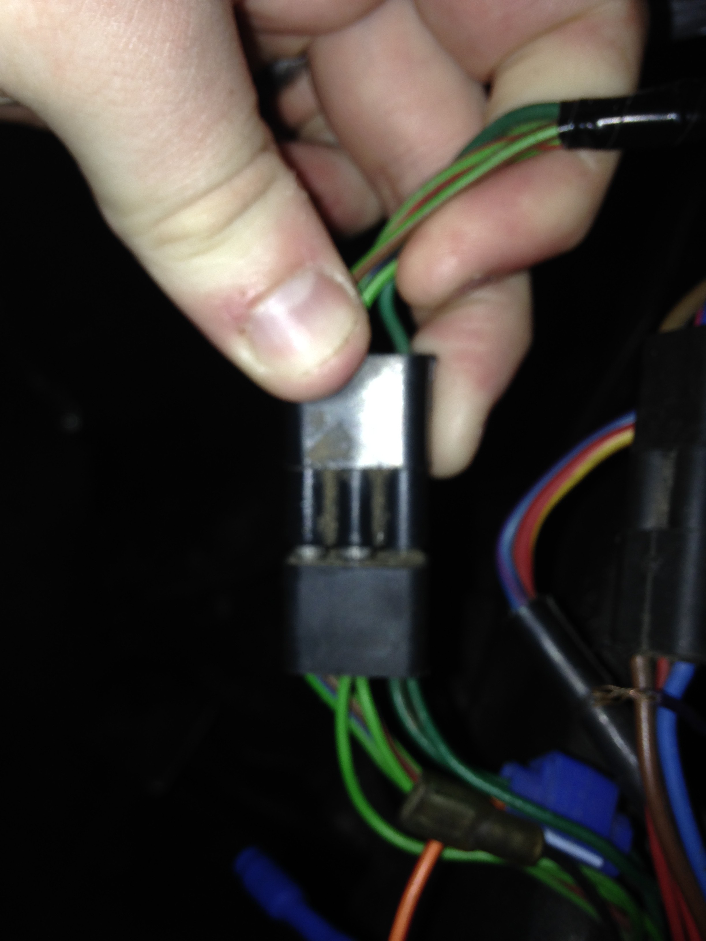
The switch is connected to the rest of the wiring loom with a connector:
Wire colour and switch functions where found to be:
| Wire Colours | Function |
| GRN | Wiper accessory power from fusebox |
| GRN to GRN-RED | Single (MOM position) |
| GRN to GRN-RED & GRN-BLU | slow constant (1st Position) |
| GRN to GRN-RED | Fast constant (2nd Position) |
| GRN-BLK - BLK(Link From Ancil. Feed in - GRN) | Screen wash switch |
| GRN-BRN | Stays at 12V whilst wiper is moving |
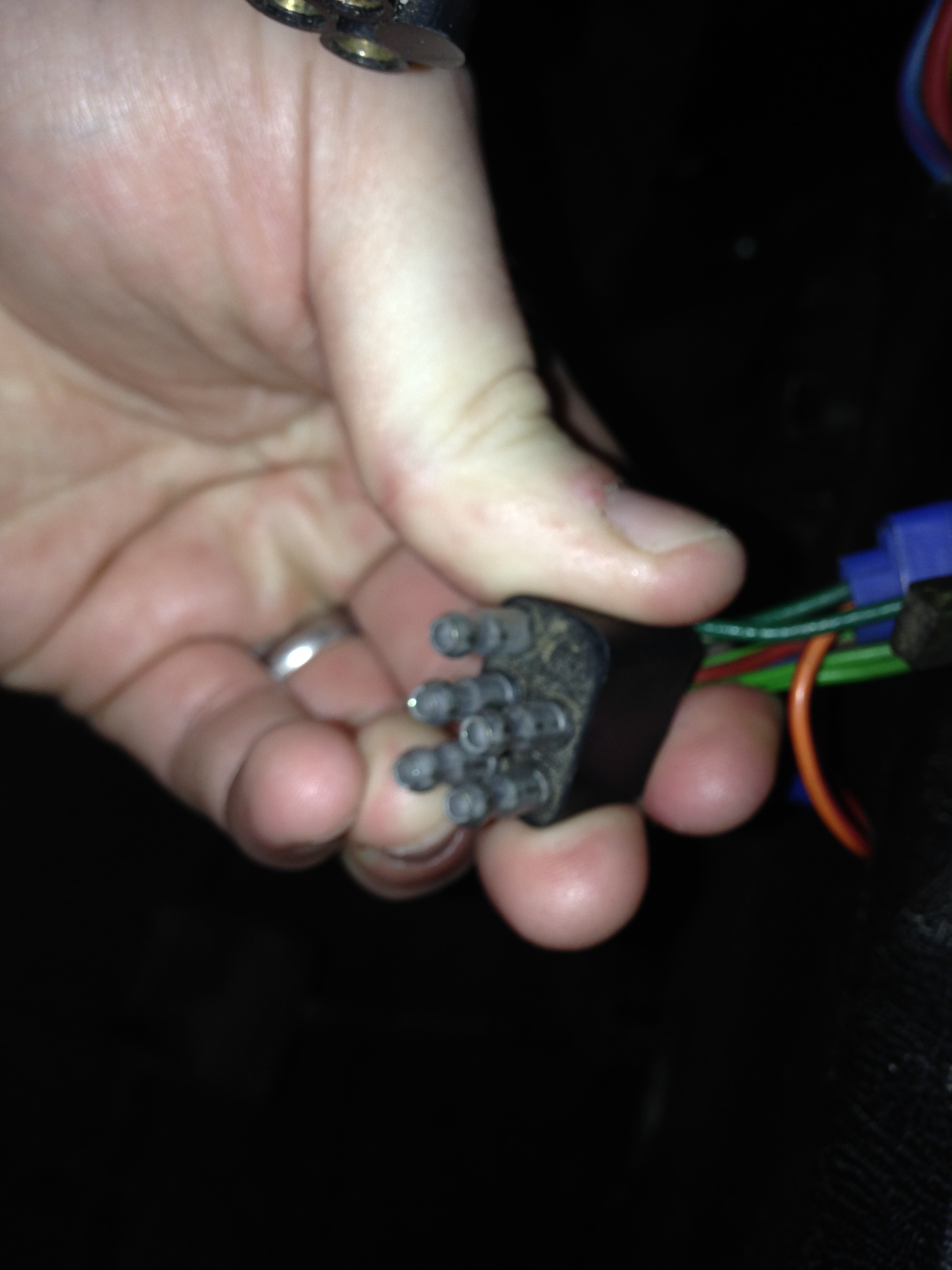
The connector is a land-rover proproprietary one and is nicely moulded in rubber. In order to interface with this I have 2 options: Find an old switch and butcher it, which I am reluctant to do, even old spares are pricey. Or use some mating bullet crimps, which fit perfectly, and run some wire behind the dash from circuit the console to the connector.
Power must come from the GRN wire as it is fused and I don't want to start a fire!
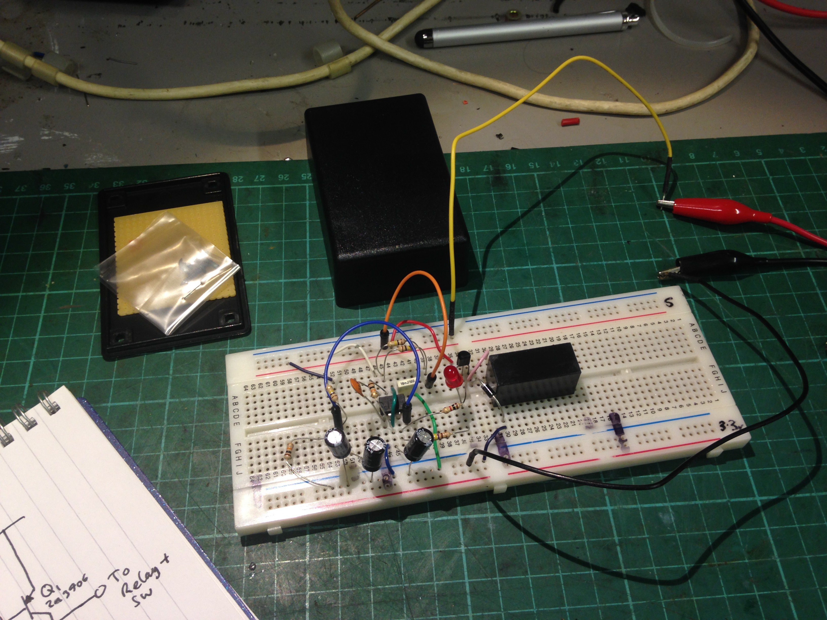
The Circuit
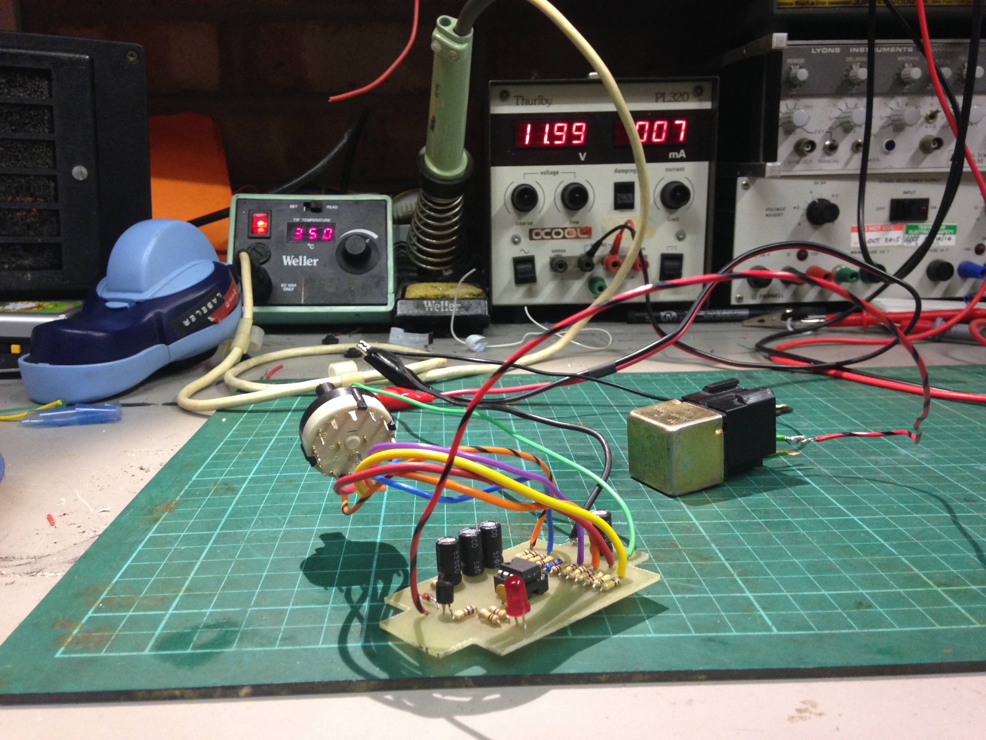
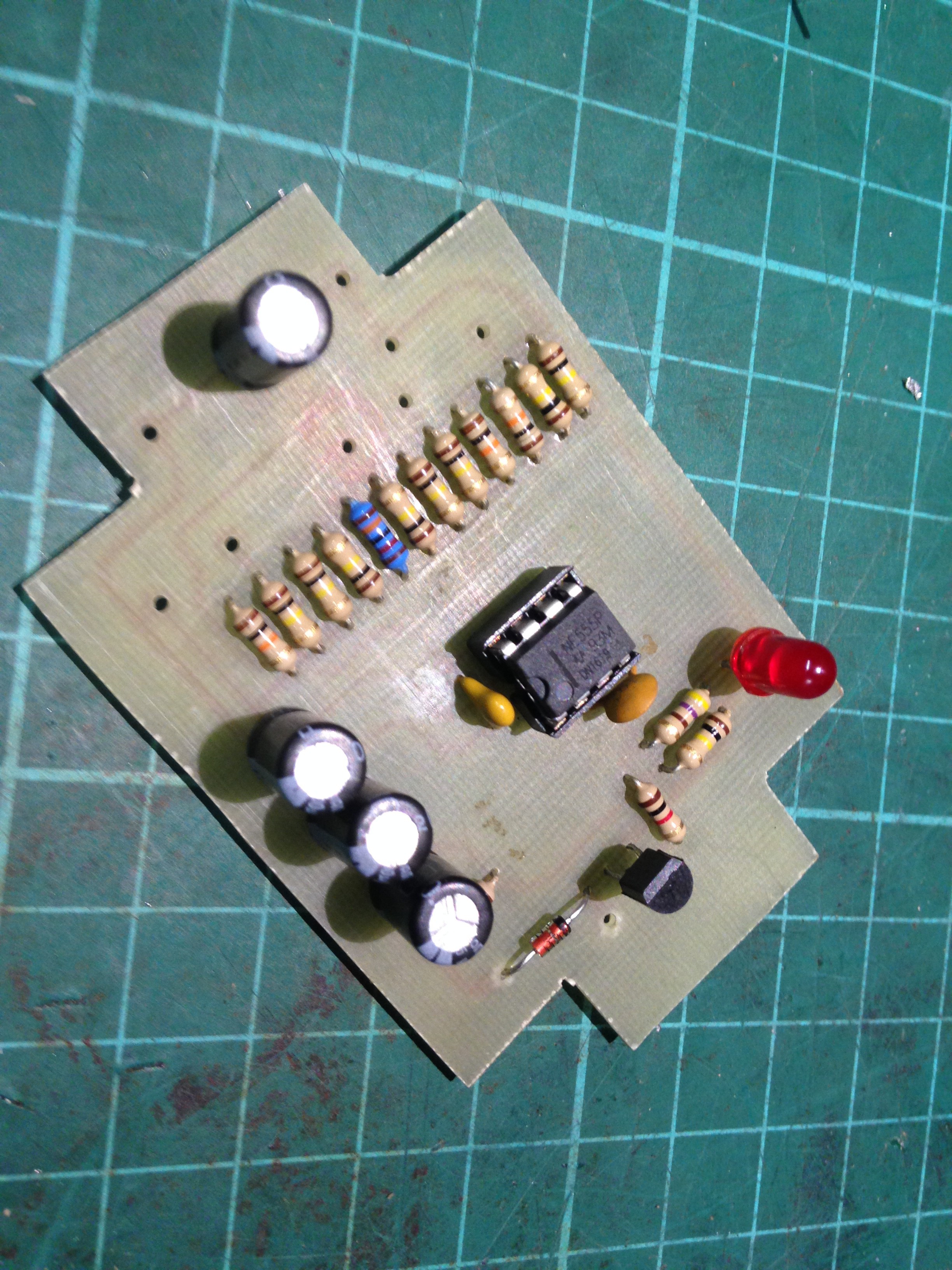
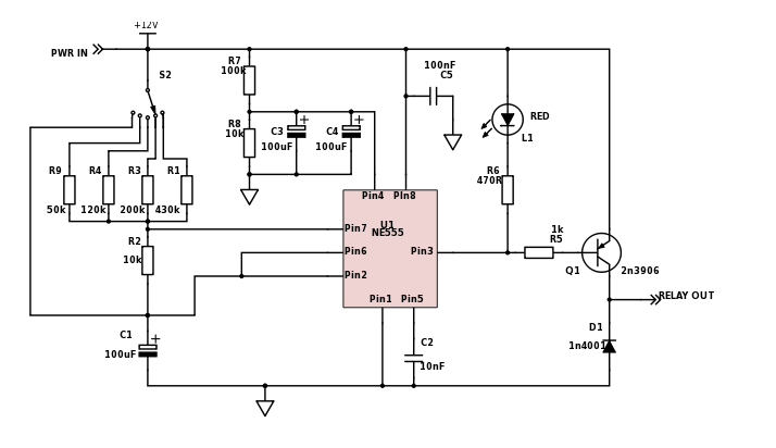
The circuit is based on a 555 timer. I require it to vary the time between wipes, so the typical 555 astable circuit is the prefect for this application.
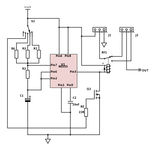
Rather than using a variable resistor, I decided to use a multipole switch and toggle between different resistor values. So say 3 different values for 3 different intervals and also another positon to allow the original constant function (S2-4 and Q2). J1 & J2 are there to suit the functionality of the automotive relay which will be connected to the output.
I chose a relay to drive output as its the simplest way when compared to using a BJT and MOSFET and not fully knowing the topology of the circuit being driven; Wiring diagrams are very vague and even if you understand it, you can't guarantee its right for your model.
The period of the 555 astable circuit is given by:
Where the space is time the output of the 555 timer is low, so Ideally I want this a fixed value as the time the relay is on for should be about 1 second-ish. This turns the output relay on by pulling the coil low. The mark time will be the time between these events, so by substituting in greater values of R1, should give longer duration between wipes.
How the circuit fits in
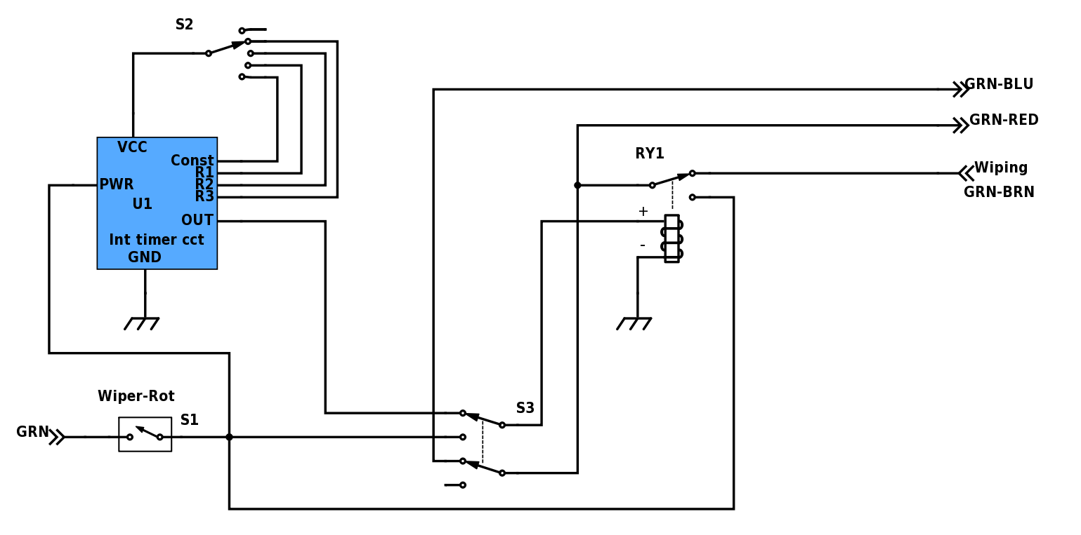
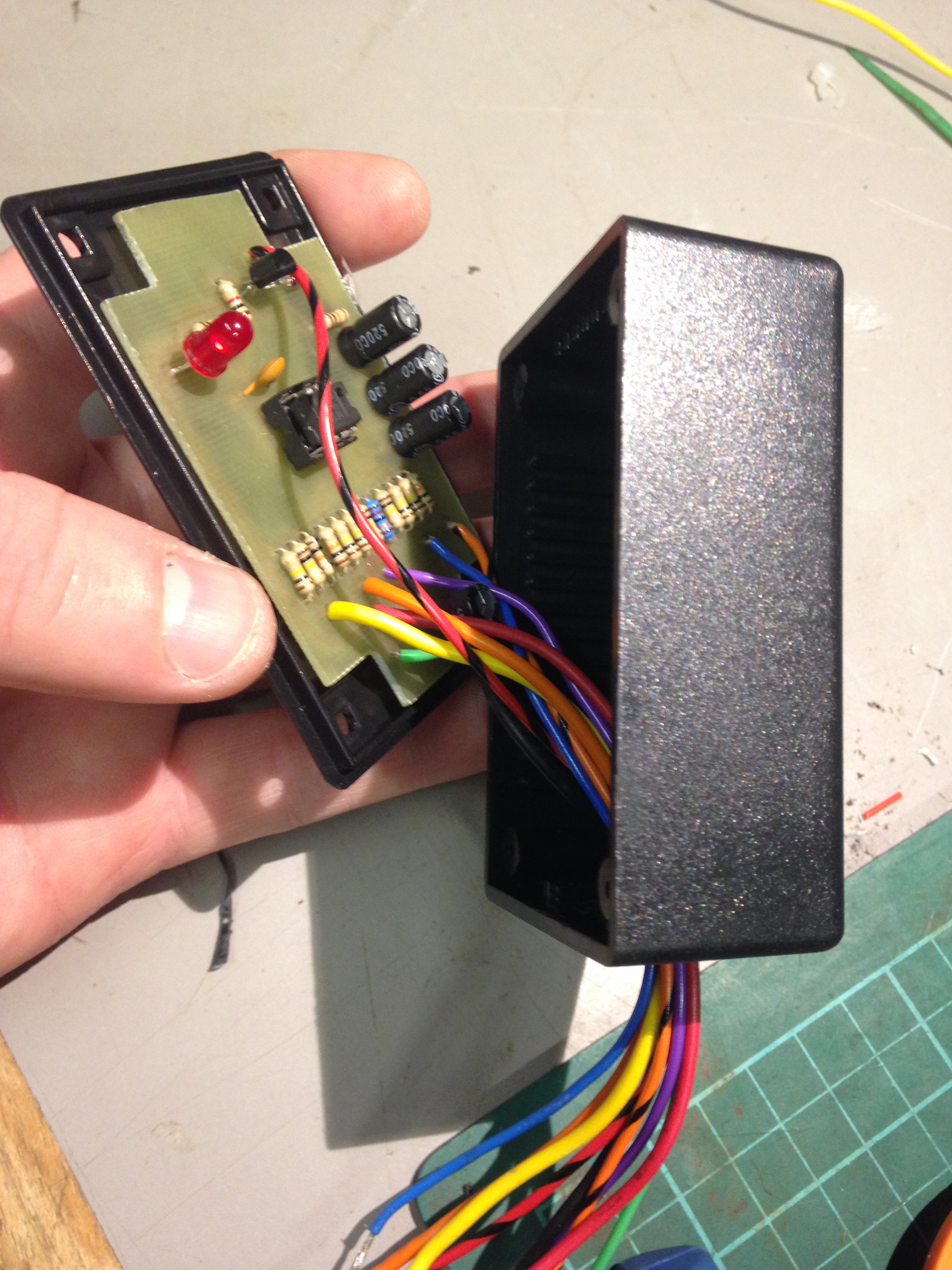
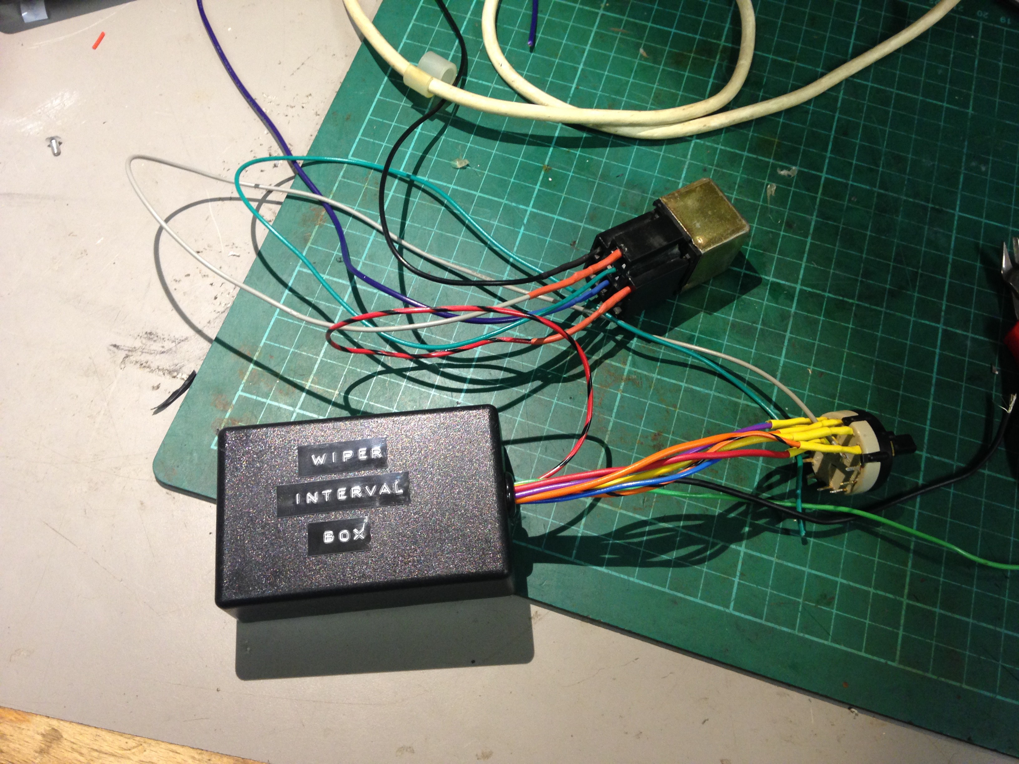
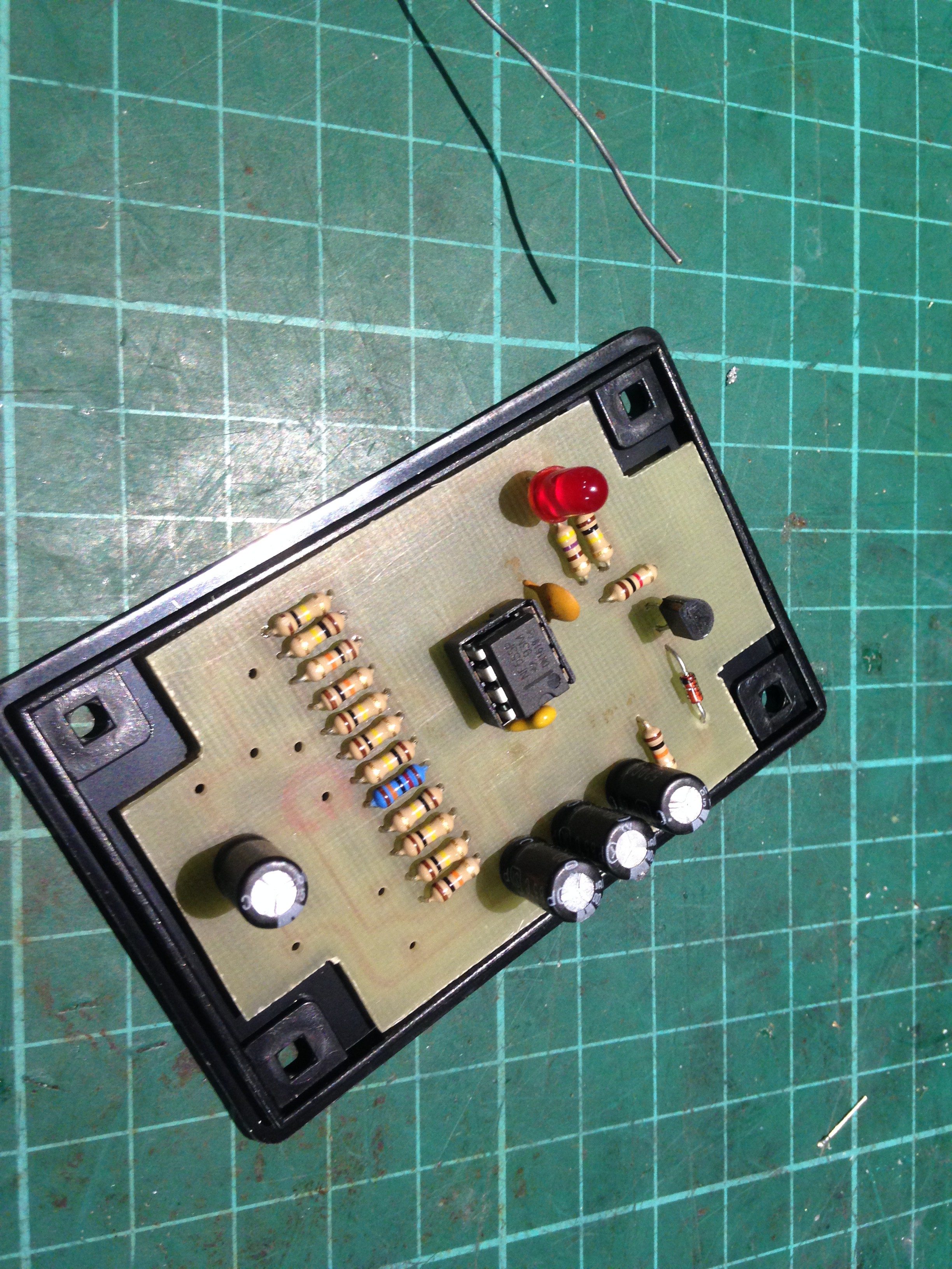
U1 is the circuit fitted inside an ABS box. S2 will select the interval between wipes. Wiper-Rot is an old double position rotatory switch with a push button function (which I already fitted to the centre console, mostly as a reminder to do this project!)
Switch S3 selects between the output of the 555 circuit and the fast constant wipe for RY1
RY1 being an automotive relay can handle quite a lot of switching current when compared to typical PCB mount relays and are easier to service so hence why that is there.
With Wiper-Rot closed and S3 in the 'up' position the timer circuit powered. When the output of the circuit goes high it will turn on RY1 for the time Tspace, which will be approx. 1 second allowing the wiper motor to start turning. After the 1 second interval and RY1 returns to the NC position, the motor wil continue to turn from the +12V recived on the GRN-BRN wire, until the wiper is parked.
With S3 in the 'Down' position, the wipers will be in constant fast mode and RY1 will...
Read more »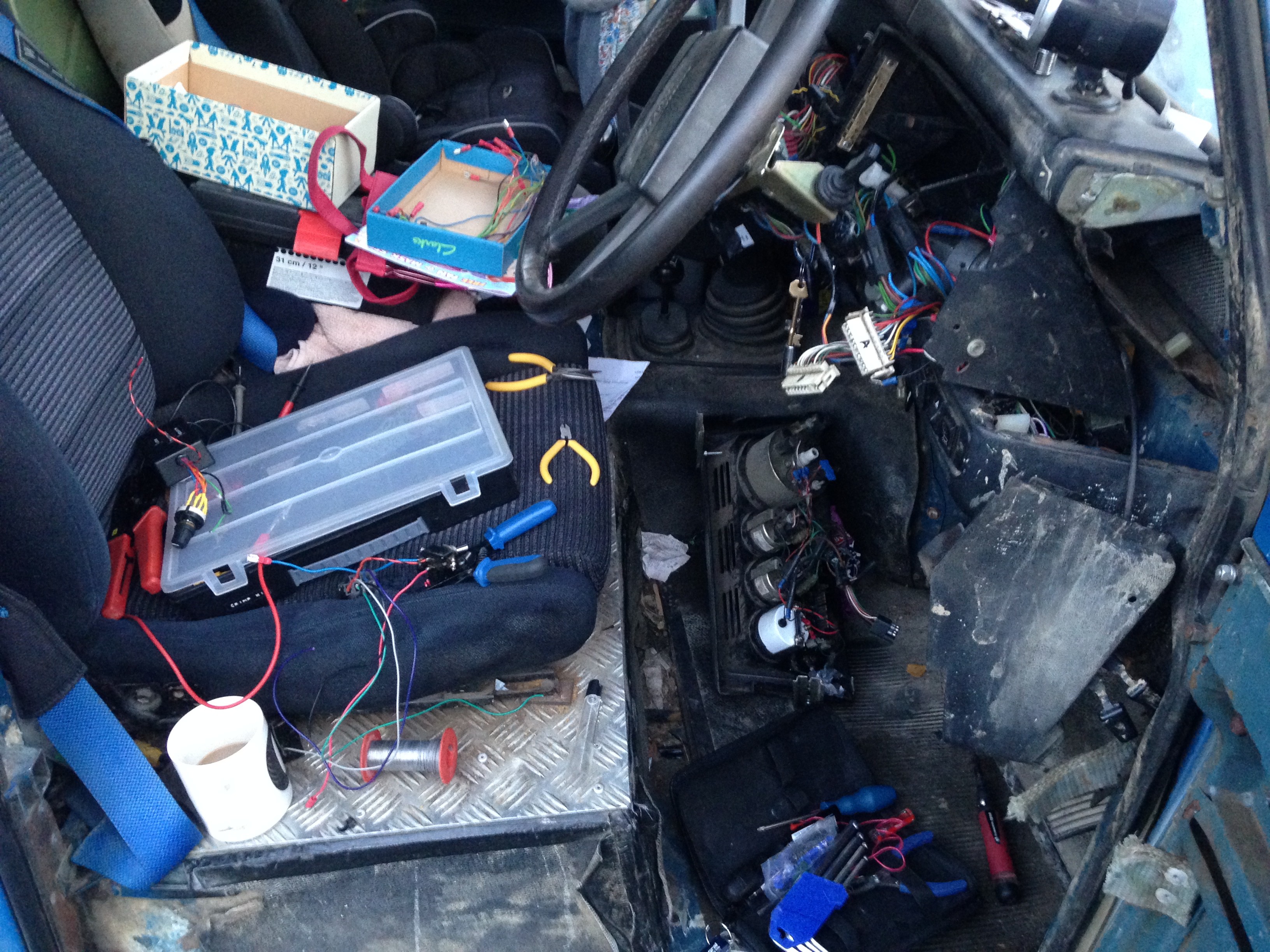
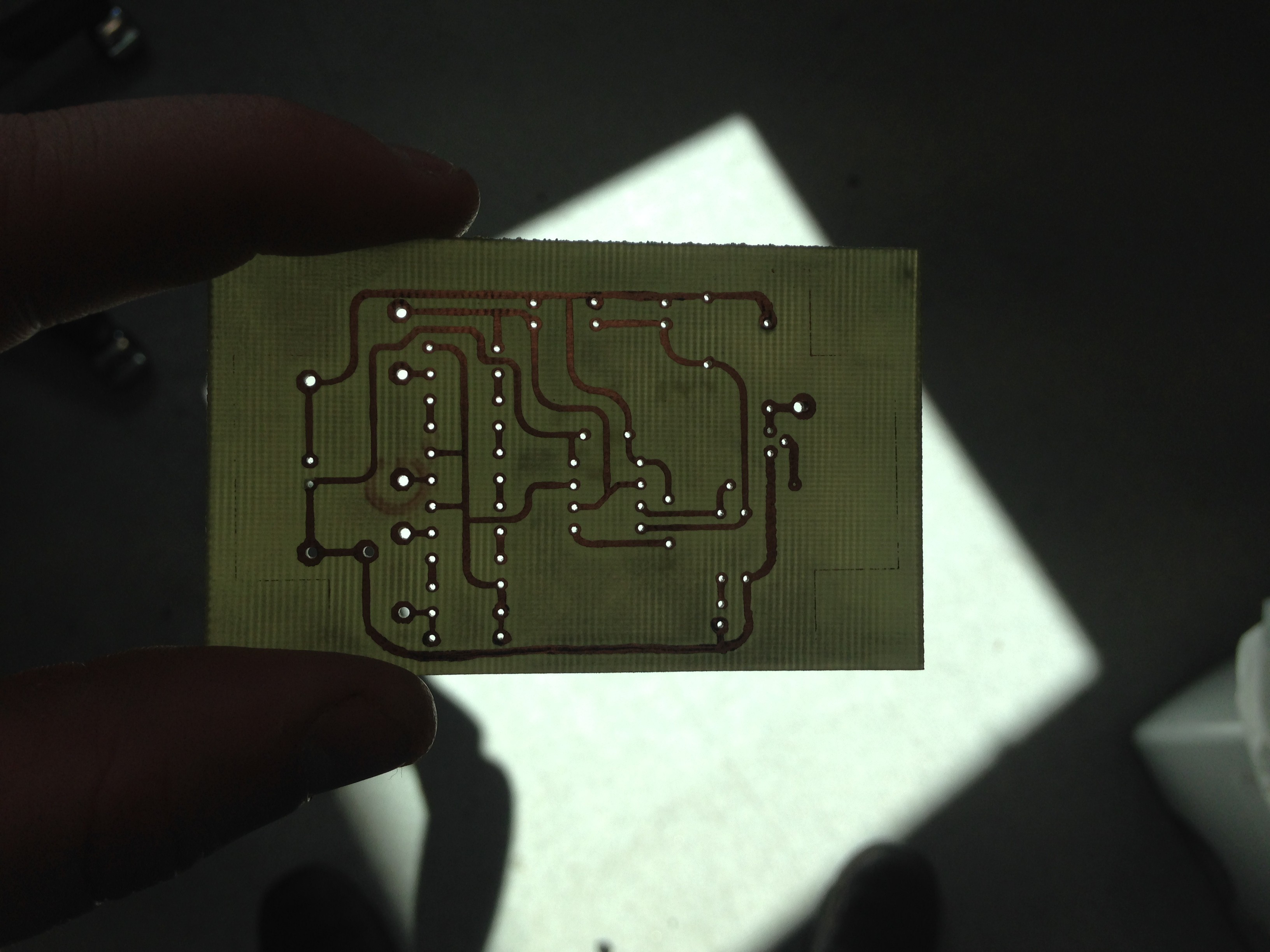
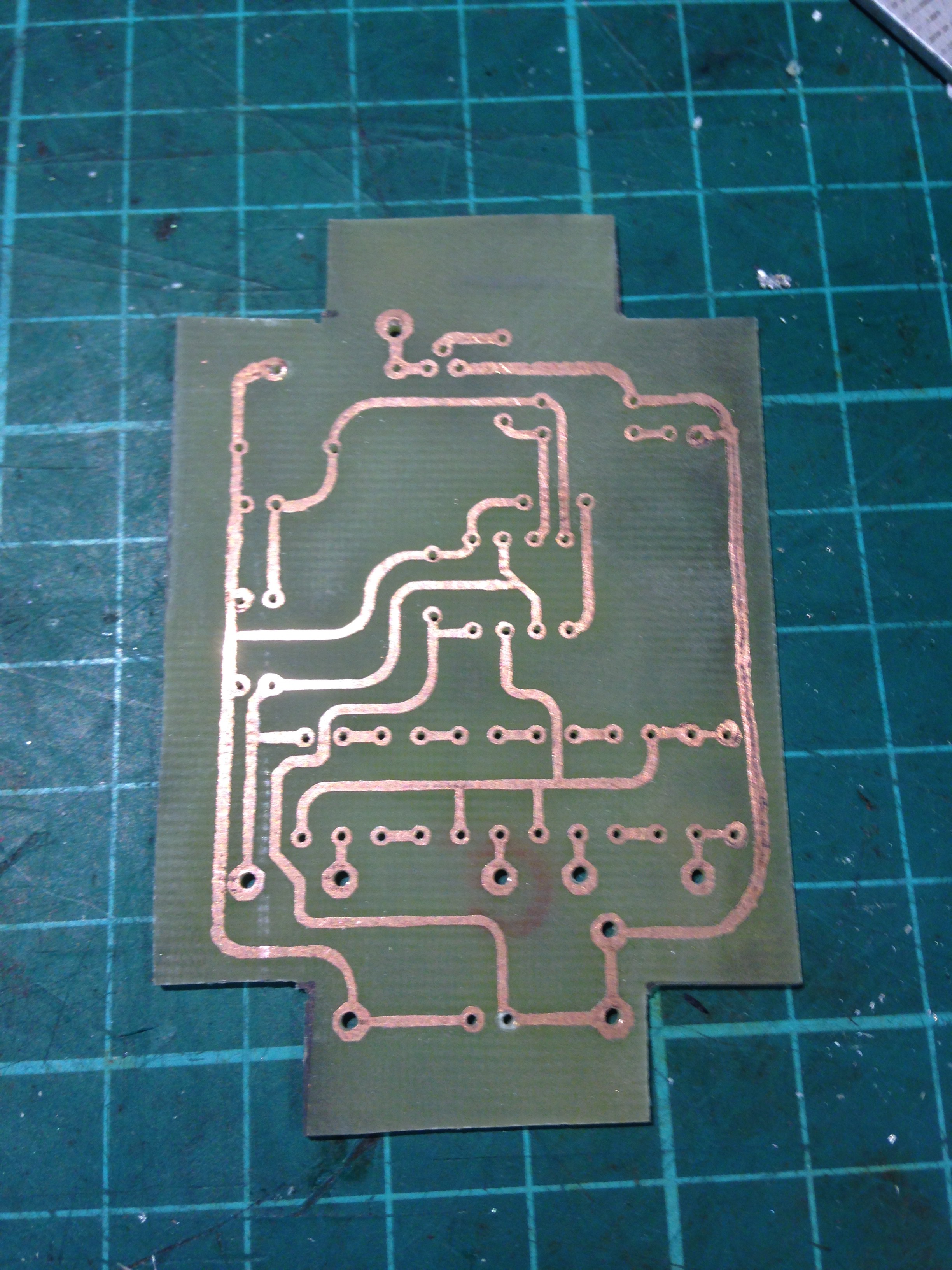
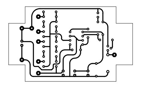 NOT TO SCALE - DO NOT COPY, BOTTOM SIDE AS VIEWED FROM TOP

 roberts.trops
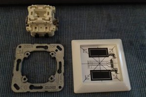
 Sandfrog
 Paul Stoffregen
 GoblinButler