 Capt. Flatus O'Flaherty ☠
In the world of professional agriculture, a lot of focus has been put on large, incredibly expensive machines that work in huge open fields where just one crop is grown. Whilst this is incredibly efficient and produces very cheap food, it's not good for pretty much everything else!
There does exist a substantial backlash against this farming model where small farmers grow 'organic' vegetables on small farms with respect to the environment and indigenous wildlife. Some might call this the 'Permaculture' movement, but I'm really not sure if permaculture would embrace modern 'robot' technology or not as historically robots take away people's jobs and help destroy communities.
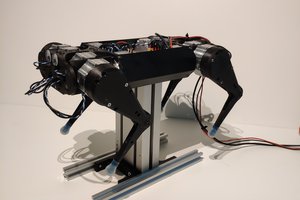
Here I introduce the Weedinator - an autonomous agricultural electric tractor that can be used on small farms to cultivate, till and weed seed beds. It can travel up and down 56 inch wide beds, several times a day if necessary, performing a multitude of quite delicate tasks which a big tractor might struggle with. Some of the key advantages are:
- Less need for heavy cultivation such as ploughing which destroys soil structure.
- Preservation of soil health by keeping essential natural micro-organisms and nutrients near the top of the seed bed rather than burying them.
- No fumes or pollution especially in glasshouses or polytunnels.
- Will help small farms compete financially with big industrial producers.
Will the Weedinator destroy jobs or will it encourage lots more people to set up small farms and help protect the environment?
Last year's efforts resulted in a tractor mounted weeding machine which worked reasonably well except for the fact that it was not accurate enough and sometimes ended up destroying the leeks as well as the weeds. The video below shows the results:
Since then I have been exploring CNC, GPS and GPRS technology and feel 97.2% confident that I can create a roving weeding machine that can also perform other tasks such as cultivating (digging) and mowing with the right attachments. Think 'Moon buggy' or the 'Mars Rover' and that will be what I'm aiming for. Actually, there is already an open source project for the CNC part - the Farm Bot.
The machine will carry it's own electric generator running on gas/diesel and be propelled forwards/backwards/sideways with stepper motors/servos. Coloured markers, detected by an object recognition system, will be placed in the soil to create grids for the Weedinator to work within as GPS is not accurate to the scale of 1 mm which will be necessary to avoid killing the crops. GPS will be used to navigate to particular fields or seed beds.
As time goes on a more intelligent object recognition system will be incorporated to detect individual weeds:
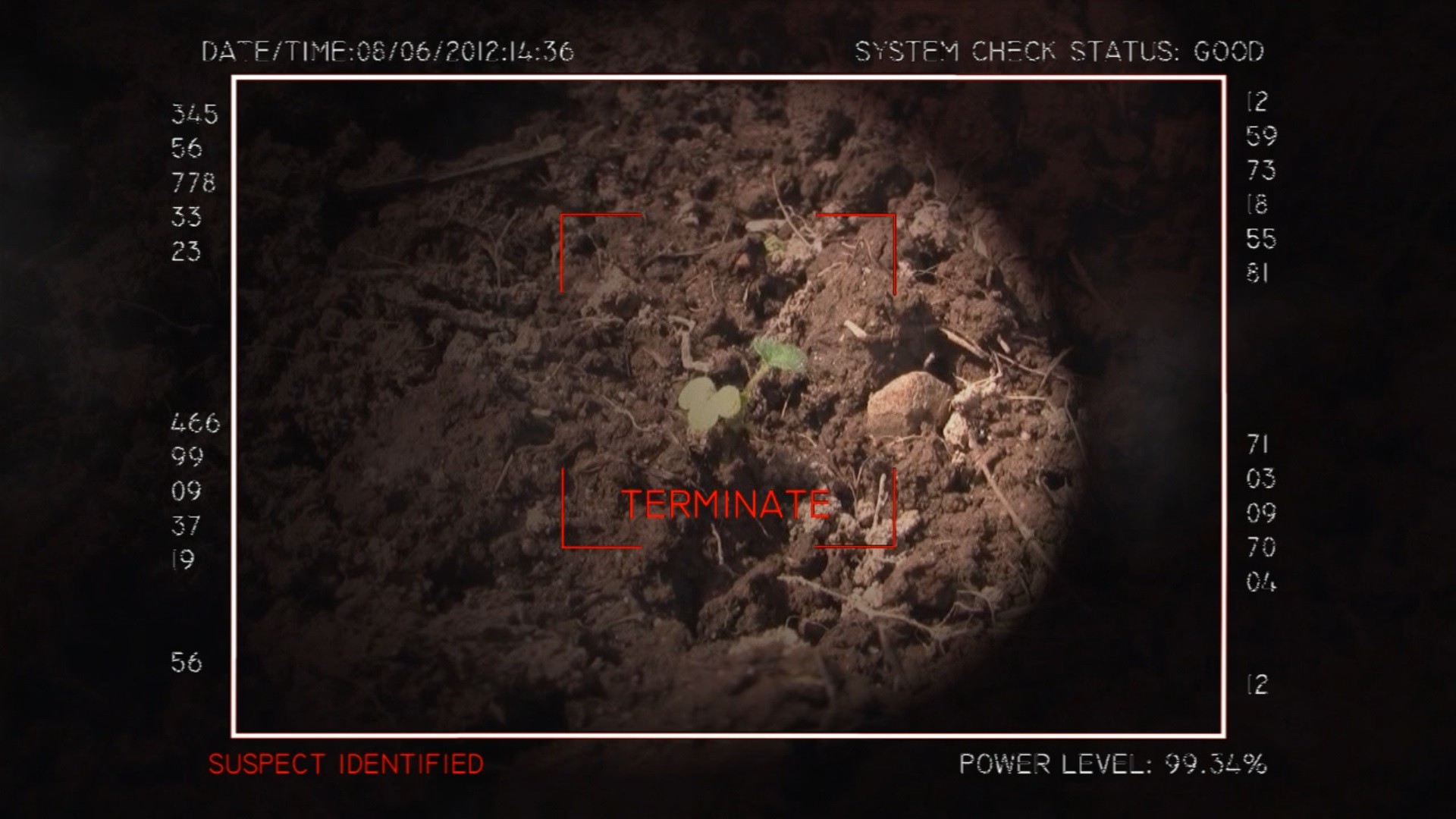
The flame thrower will be mounted on a normal CNC frame with 3 axis of movement and the nozzle itself will be shrouded by metal sheet to prevent damage to the crops themselves. Individual weeds could be zapped by a small gas powered butane torch as used by a chef when making crème brulee.
This may seem like a very ambitious project, but the actual chances of achieving success are quite high. Much of it depends on the quality of the code written for reading the GPS data and transforming that into real-time steering and motion. It all just seems like great fun to me!
Programming new coordinates into the Weedinator via the cell phone network is not going to be difficult as much of the task of handling GPRS data has already been covered in my weather station project.
There is a risk that as the project evolves we will run out of programming space or computing power on the MCU ...... So ....... Just add another one and get them talking to each other via the I2C bus, which I also had up and running on the weather station project, although my code for this communication does now seem a little bit 'clunky'.
The greatest 'risk' is due to the cost involved in buying all the components - the GPS system is expensive...
Read more »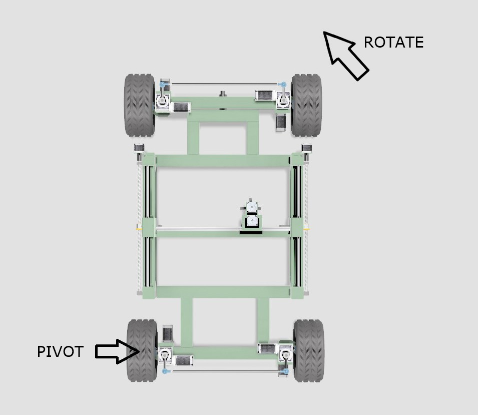
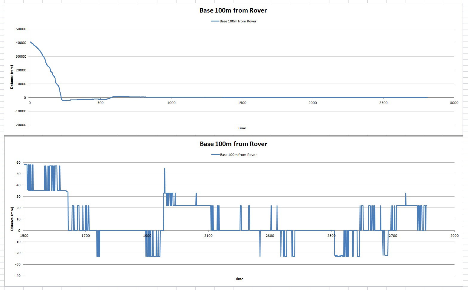 You really can't have enough graphs in a project and testing the Sat Nav always produces a shed load of data. This time the Base and Rover are separated by 100 m to see what error, if any, is added. I can't decern any noticeable additional error at all. The 'Fix' was obtained at about 1650 on the horizontal and from then on the total error was pretty much 40 mm, as before :)
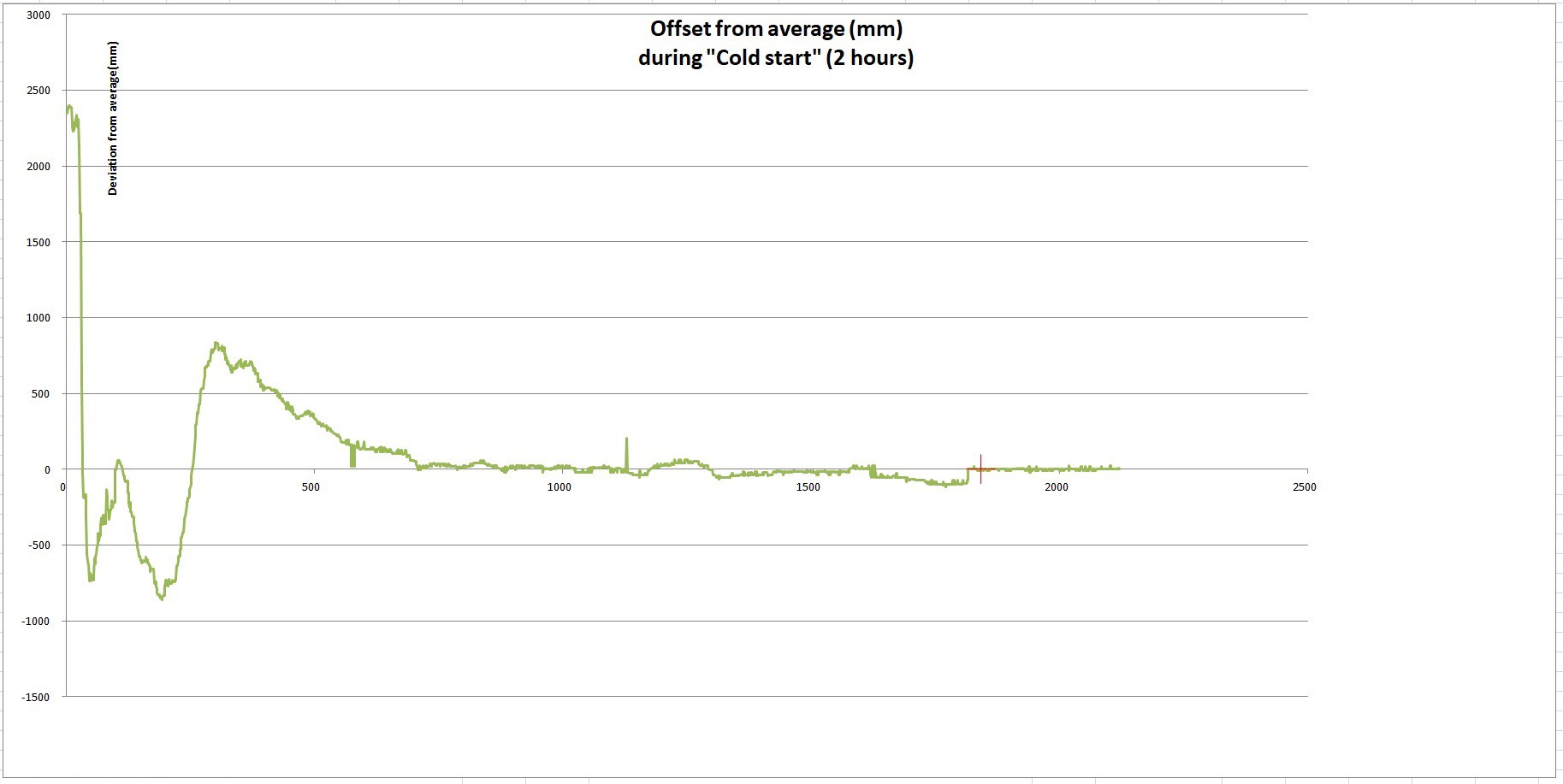 On 'Cold Start', the module started off with lots of error and gradually the error became reduced until, after about 2 hours, it got a RTK fix between rover and base (shown as the red cross). During that 2 hour period, the base module is continually building up and updating an average value for latitude and longitude and after the pre-programmed time interval decides that it has got a good fix.
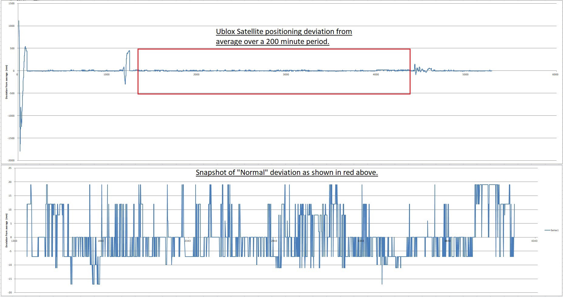 The lower graph is a 'zoom in' on the red box in the top graph and shows a good representative snap shot of the Ublox performance, with total deviation of 40 mm, with is good enough to guide the Weedinator to it's loacation, but possibly not good enough to cultivate the soil around individual plants?
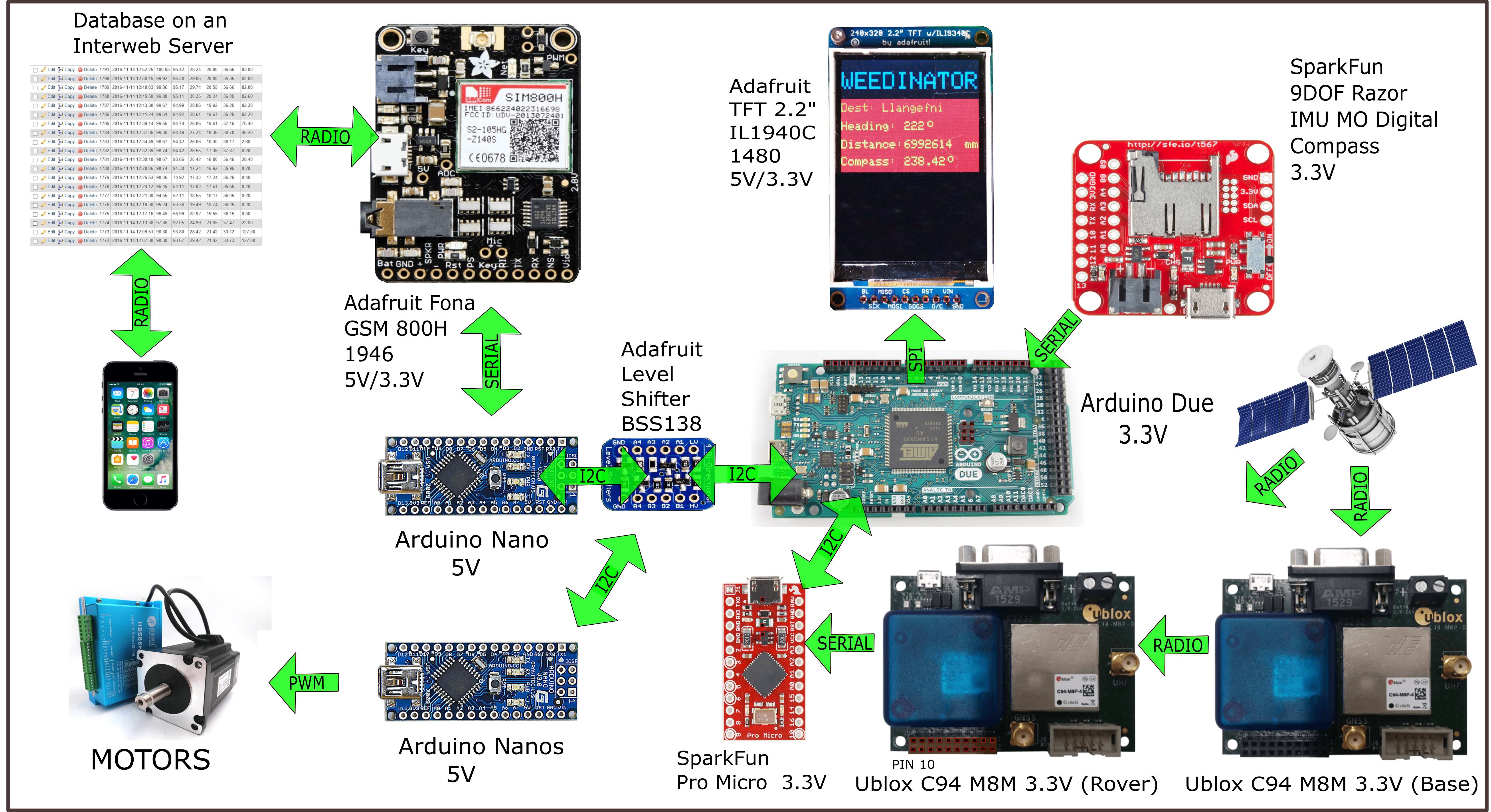
 Obviously I don't want the machine to actually go there - it's just a test to see if I'm getting correct results.


 Peter Wasilewski
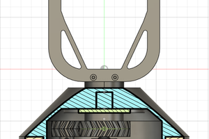
 caver.adam
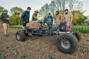
 Ossum
Ossum
interesting project! I have similar ideas but a bit simpler mechanically, what is your reason for building the wheel/suspension arrangement in such complex manner? does the whole vehicle really need to shift hight? and why do you need the 3rd axis on the cnc-part when you have wheels? my idea is to build something lighter with 2 electric bicycle wheels for most load and 2 smaller swiveling wheels as support.