 Greg Stephens
Low-Friction slide-bearings

Compression strength 375x its own weight.
Repositionable
The most general purpose hobby vise.
Already have an account? Log in.
To make the experience fit your profile, pick a username and tell us what interests you.
Low-Friction slide-bearings
Compression strength 375x its own weight.
Repositionable
We are gearing up for our Kickstarter campaign! Just 10 days away!!!
Commence the freak-out: !!! õ¿õ !!!
Note: My Non-Disclosure Agreement is keeping me from releasing photos/videos of our prototype. But, I've been given permission to make something special for our hackaday followers on Friday (9/08).
[Making of 'The Maker's Vise' Kickstarter Campagin Video]
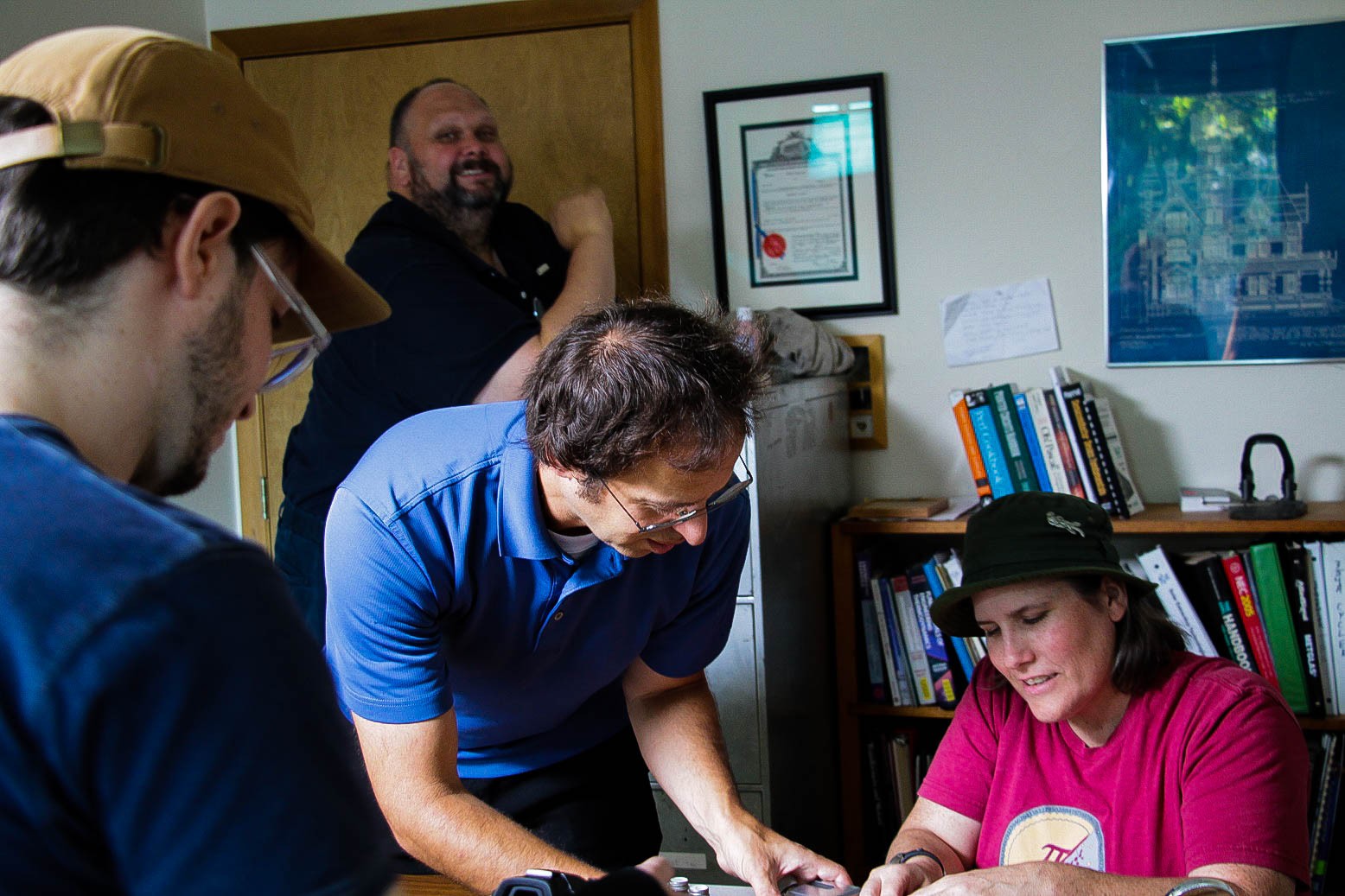
What I can do now... is give a sneak preview of our kickstarter video. Here some candid photos behind-the-scenes:
1. Vise Used for Model Painting
2. Interview of the Founder
3. Say hello to the videographer! Ty Pardon Media for helping us on such short notice.
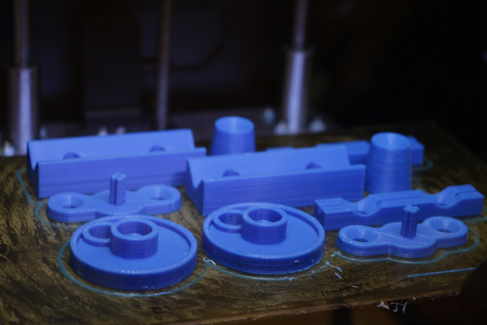
Alright! Let's start testing custom jaws and handles. 100% fill..
I can already tell the printer tolerances are going to mess with me.. Every slot/hole seems just a little bit too small.
I am floored... The Maker's Vise, hands down, is now the best vise I have ever used!
..it's easy to use, it's reliable, it's FAST. I'm absolutely dying to make a video to show our progress to you guys. I've almost snuck in after work to make a demo video for our hackaday audience, a couple times now. But, my boss has warned me that too many public disclosures can ruin a patent application. So, i'm standing on my hands for now.
Less than a month till our crowd-funding campaign launch. Things should really start heating up.
With a final adjustment made to the bolt angle... we were able to again make an improvement on compression strength. Now at 3x the original grip force!!
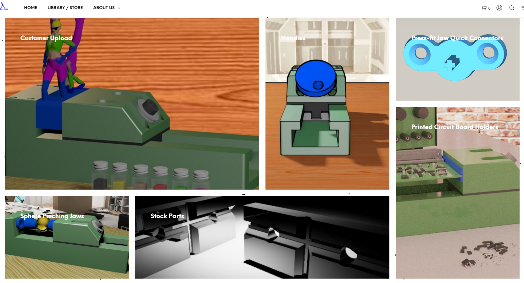
I threw together a website for everyone to look at and see what The Maker's Vise has to offer.
It's got the following pages:
HomePage -- Product Description
Library / Store -- This is the digital design library I started for custom vise parts.
About US -- Our Story + FAQ
The next step is a big one! A fun step,.. actually! It's time to find things that our vise is useful for, and design parts for it. Send me your feedback! Let's talk about what would be cool add-ons. Everything we can add will make The Maker's Vise a better product.
Wow! It's been a while since our last log post. Fear not friends, we have not fallen off a cliff. We've been working fervently on our design.
You may remember that our vise was maxing out at 500 lbs. of reasonable clamping pressure (Link Here). We promised that most of our design efforts would be focused on bringing this clamping pressure up to a more useful number. ...at least 1,000 lbs or the project would be scrapped.
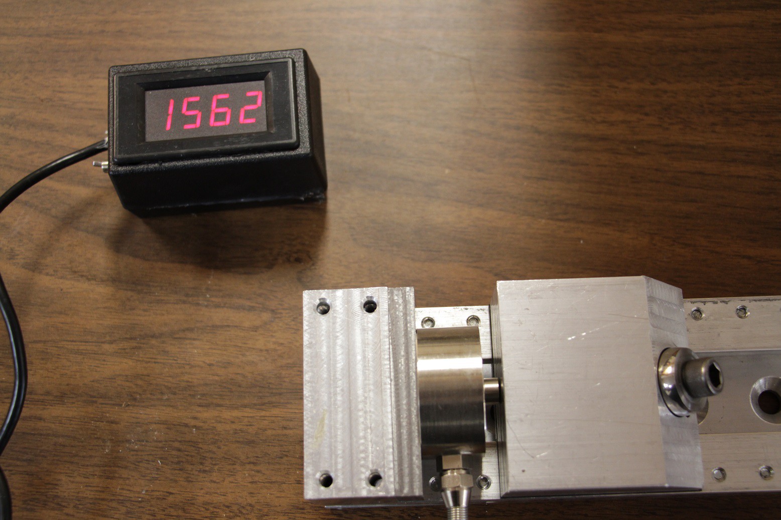
We've made it! The Maker's Vise is turning into a real beast of an apparatus.
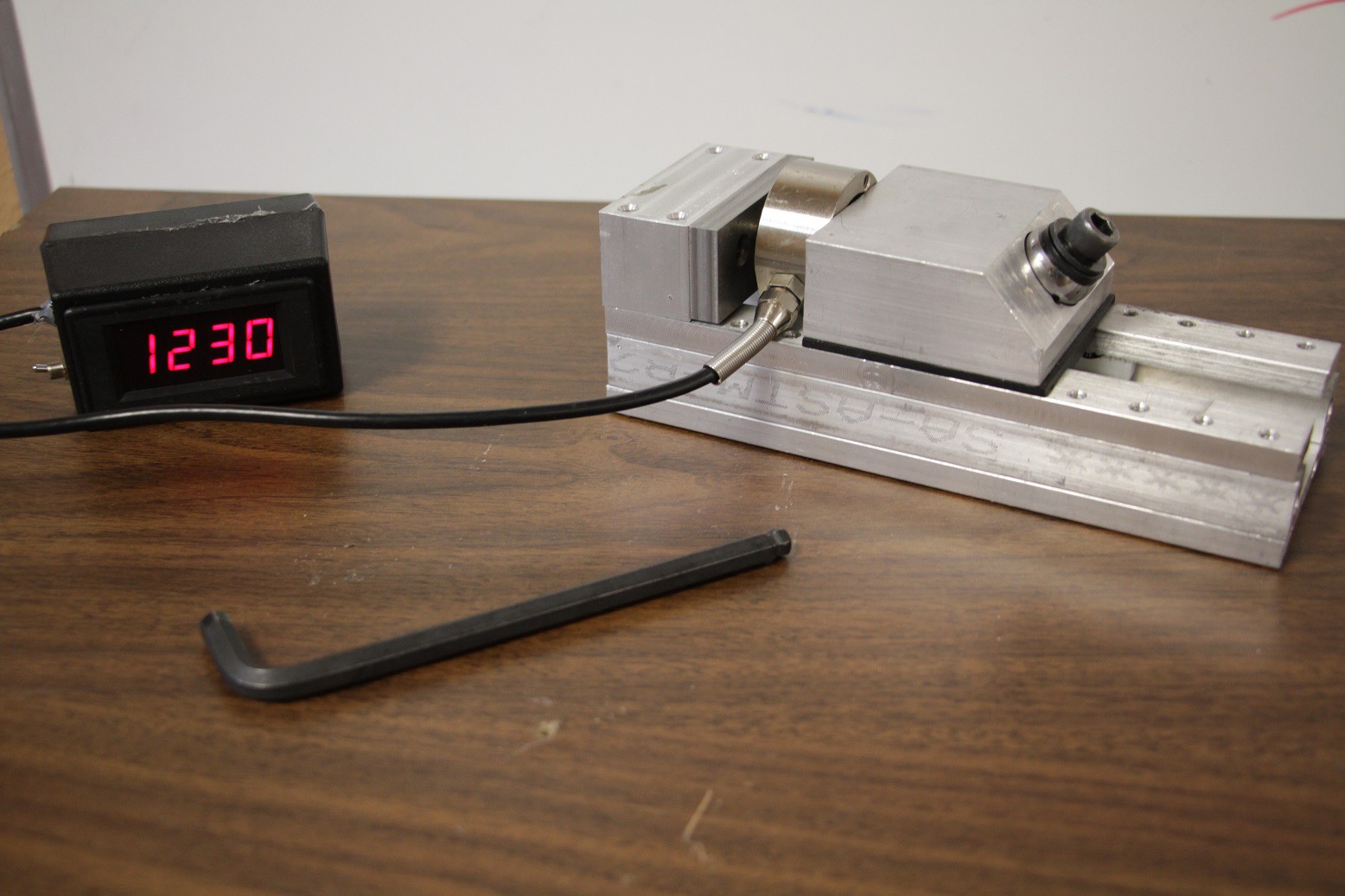
Check out these numbers:
We're now measuring over 1,200 lbs of reasonable clamping pressure!! This beats out a majority of the vises we have collected from the open market. ..which is cause for excitement.
Today is a good day!
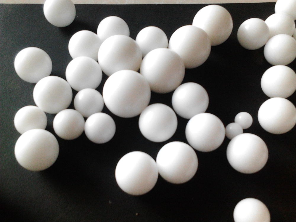
We wanted to do some rough simulation of our Polyoxymethylene (Delrin) bearings to determine if they can handle the pressure we expect under load! So,.. I learned how to operate SimScale over the course of the last week. Simscale is a rather easy to operate web-based mechanical engineering simulation program.
We compared our current prototype bearing profile with a hypothesized newer profile with potentially better stress relieving attributes.
Simulation #1) Current Bearing Profile. 1" Diameter.. Cut 1/4 off at the top.
Simulation #2) Hypothesized Profile. 1.25" Diameter.. Cut halfway through.
Polyoxymethylene--
Young's Modulus: 3.1*10^9 N/m^2
Density: 1,410 kg/m^3
Poisson's Ratio: 0.44
Applied force: 2,000 lbs Normal to flat face.
Constraints: Round support structure cradling bottom half of bearing
Notes: A majority of the strain appears to be forming above horizontal diameter.
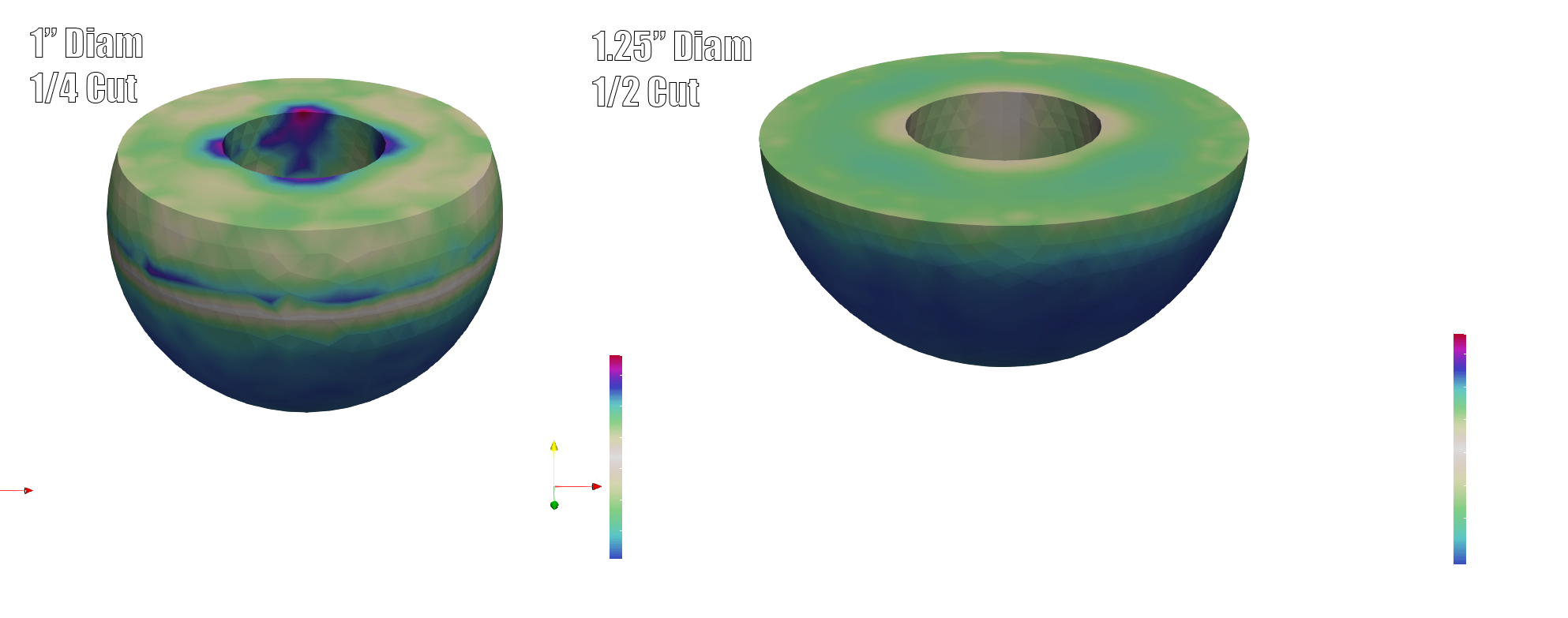
Displacement [m]
Notes: Any surface area not supported is experiencing some displacement. This is a good argument for the half-ball rather than the full 3/4 ball we have now.
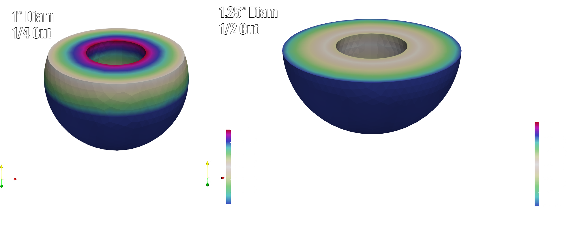
Cauchy Stress [Pa]
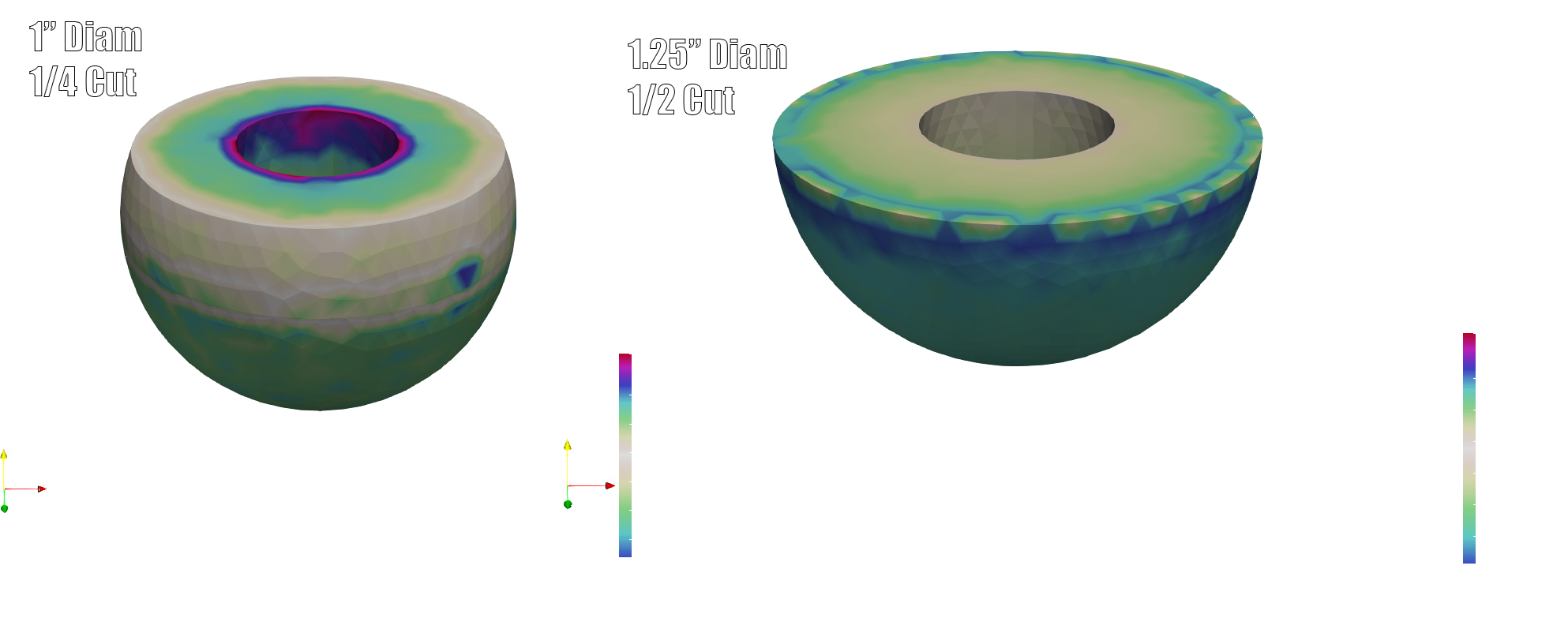
Notes: Cauchy stress indicates the stress experienced during displacement.
von Mises Stress [Pa]
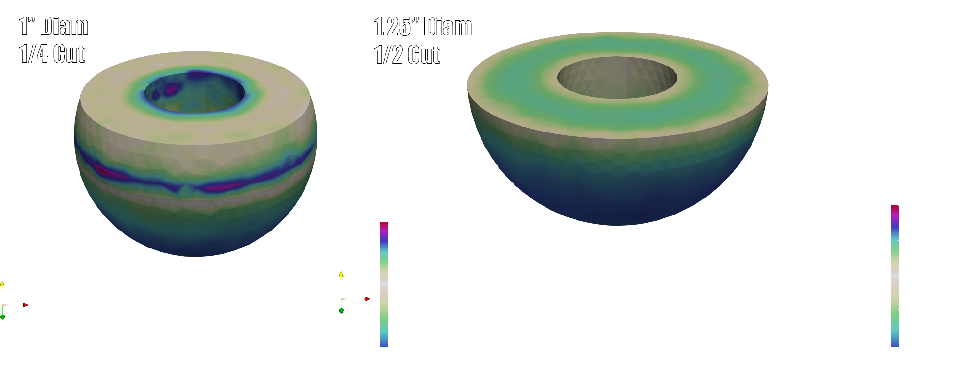
Notes: Now this is the plot we're really interested in! The VM stress plot will tell us whether our bearing will break under load. The 1/4 cut 1" ball results in a peak VM stress of approx. 3,000 psi whereas the 1/2 cut 1.25" ball results in peak stress of approx. 2,000 psi.
Conclusion-- The compression strength of Delrin is approximately 5,000 psi. Our current setup may be getting a little too close to that number for comfort. Cutting the ball in half certainly reduces strain. Increasing the bearing size certainly increases our ability to disperse applied stress.
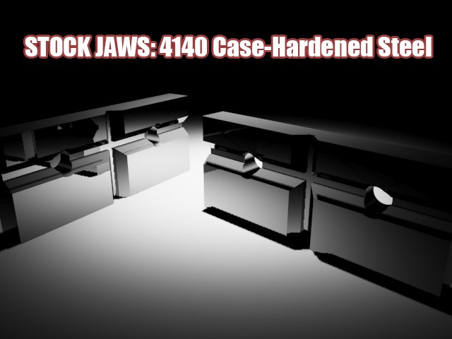
Although, we do recommend custom jaws for most applications.. sometimes you just want a brute strength solution.
Needless to say..
A quality pair of steel jaws with nice crisp edges are invaluable for applications such as.. bending small brass cutouts into oscilloscope adapters. Click here for tutorial.
We think these jaws should come standard with the Maker's Vise.
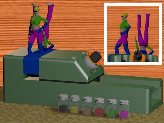
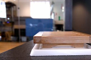
I had an idea to make painting 3D printed action figures easy. Make a negative imprint of your model's "feet" and "head". This way you can paint the top, let it dry.. flip it over, then paint the bottom.
Because the plastic she would be printed from is the same color plastic as the vise jaws.. it looks like she was made as part of the jaws. That wasn't intentional.
Perhaps a model car or airplane would make a better concept drawing?!
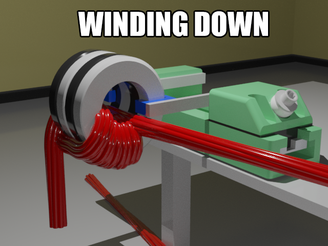
I'm not sure how many of you out there wind your own transformers and inductors.. but we do! And, we know how these torroidal shaped iron cores can be difficult to wrap wire around. Our vise aims to make tasks like wire winding easy. I envision our vise having jaw extension attachments, as depicted above, just for jobs like this.
I'd like to continue making a series of concept images of what our vise will be able to handle with custom jaws. Multiple images a week. If you have ideas for objects you'd like to clamp, please comment or send us a message.

I'm sure you've already tried and rejected this but just in case... I really like the way your prototype can quickly slide up and down the notches when the pressure is released. Instead of the allen bolt to tighten, could you use a cam bolt or two bar lever mechanism, like https://goo.gl/images/gi8XCy? It seems easier to generate force and could use standard parts, perhaps allowing your design efforts to focus on other features (like the fixturing that maybe makes the difference between another vise and a super cool tool).

Hey Simon, that's a fun idea! A locking lever mechanism would surely make our vise extra simple to operate. But, I haven't come across anything with enough clamping strength suitable for our vise. The toggle clamps i've seen, like the one in your example link, fall short with a clamping strength of only around 100lbs. We'd like our mechanism to have 10x that holding strength.
Thanks for the feedback, i'll keep thinking about it..
Just to pop it down on the project page - a vise powered by any old pair of locking pliers would be cool. Just need to convert the forces and make the adjustments easy/fast. Locking pliers even come with a built-in quick release and fine adjustment of clamping position/force.
Came across this today. It reminded me of your lever mechanism idea. I kind of want to buy one to see how well it works.
https://www.walmart.com/ip/ST-QUICK-VISE/55604972?wmlspartner=wlpa&selectedSellerId=0&adid=22222222227092949532&wmlspartner=wmtlabs&wl0=&wl1=g&wl2=c&wl3=207447825522&wl4=pla-366218657244&wl5=9032830&wl6=&wl7=&wl8=&wl9=pla&wl10=8175035&wl11=online&wl12=5560...
Initially I thought it looked terribly flimsy but there's a chance it is useful. Not for what it seems like your vise could do but for light tasks.


 Giovanni
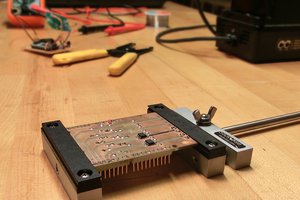
 Alex Rich
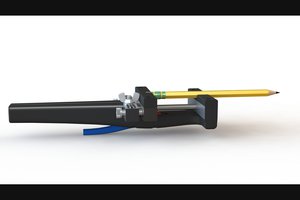
So that wouldn't help you save time if you had to design and make your own. Oh well, it might be nice to borrow from the mechanism: