 Jorj Bauer
Decision the first: yes, I'm going to keep the random-parts-bin-build model. This isn't about making a useful computer; it's about making something useful out of the old parts I've got in the house. So yes, the MC824 with gold leads is going to find a home in this build.
Which leads to the second decision: the boards will be small, and stacked high. I don't know if I'll build clunkers so I want to be able to experiment and replace easily.
Third decision: I'm going to use 2x20 pin stackable headers, because they're readily available for the Raspberry Pi. Looking at the signals I've got there are three groups that could be on their own headers:
- Core functionality: Power / Ground / clock; 16 bits of address bus (if I actually use it, the design so far hasn't called for one); 8 bits of data bus
- Status registers: Power / Ground / clock; 8 bits of register A; 8 bits of register B
- ALU / control lines: Power / Ground / clock; 4 bits of status; 16 ALU control lines
If I were to drop the not-yet-needed address bus that's 47 bits. Since it won't fit on one header there's no reason to drop the idea (yet). But 3 separate headers would be overkill. So I'm going with two: the status registers and ALU will be on one, and the core on the other.
Given the turnaround time on PCB fabrication I'm hoping to get at least a couple of the boards out at the same time so I can see how they work together (particularly with the stacking bus). And I started in the same place I did with the original -- the clock.
This clock circuit is built around three different 555 timers, doing three different things. (If I'd had a 556 in my parts bin, it would have been a good choice to reduce the part count. But I didn't, and I have a plethora of mismatched 555s.)
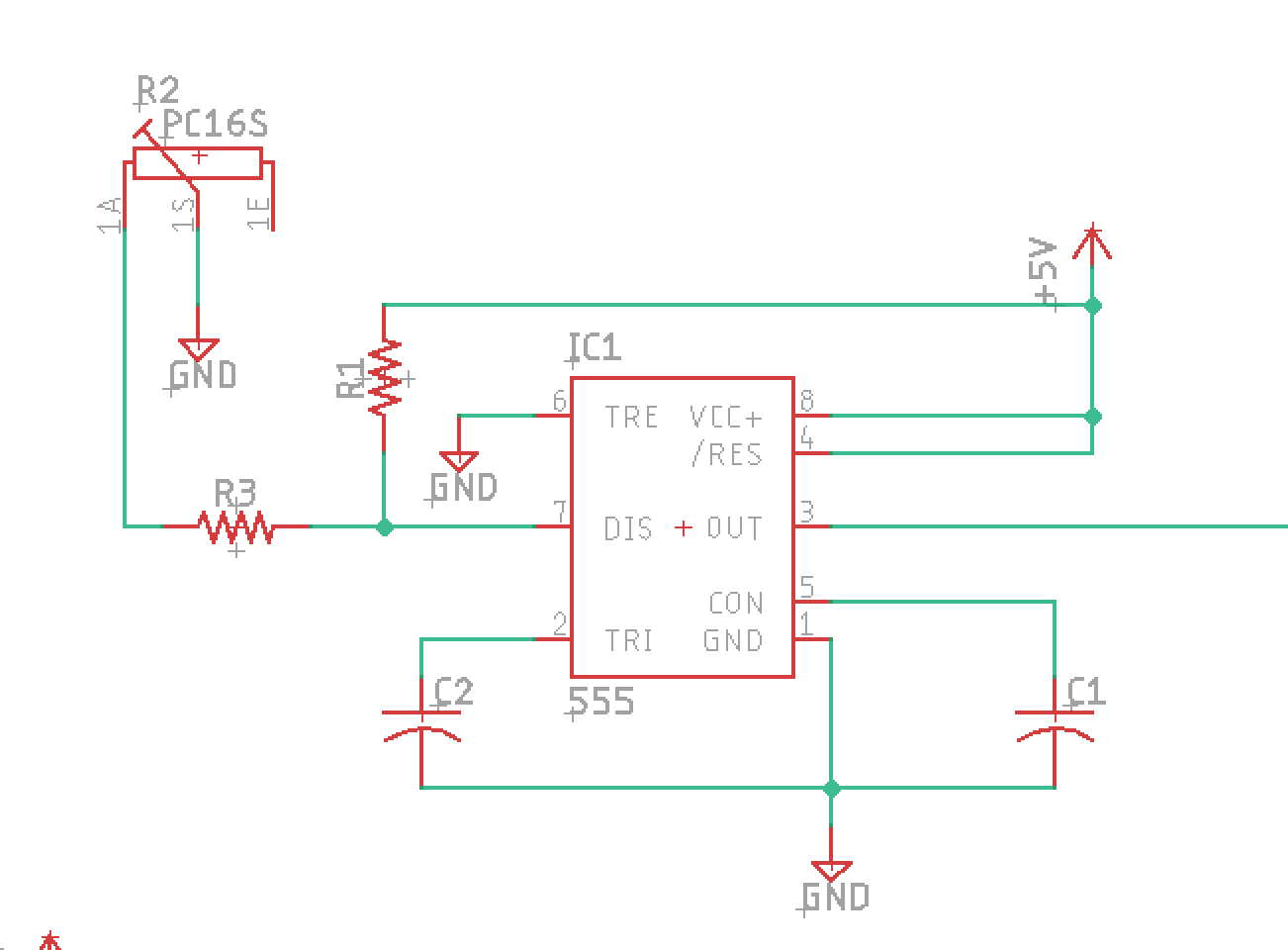
The first 555 is the heart of the clock. It's a standard astable 555 circuit with a potentiometer to change the frequency.
But I had two other goals here - a way to stop the clock on demand; and a way to step the clock forward manually. So let's add a switch to stop the clock and something to debounce the switch. The debouncer is another 555, operating as a schmitt trigger:

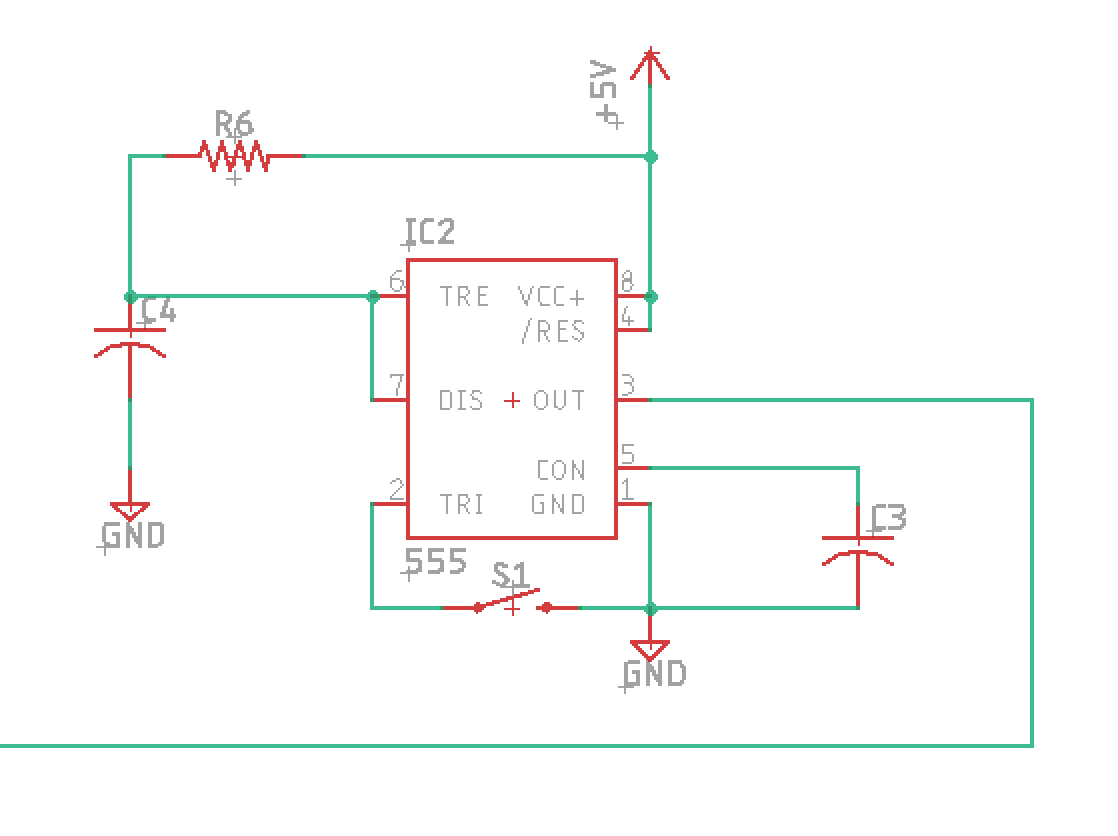
And then we've got a button that creates a single clock pulse, using a monostable 555 arrangement:
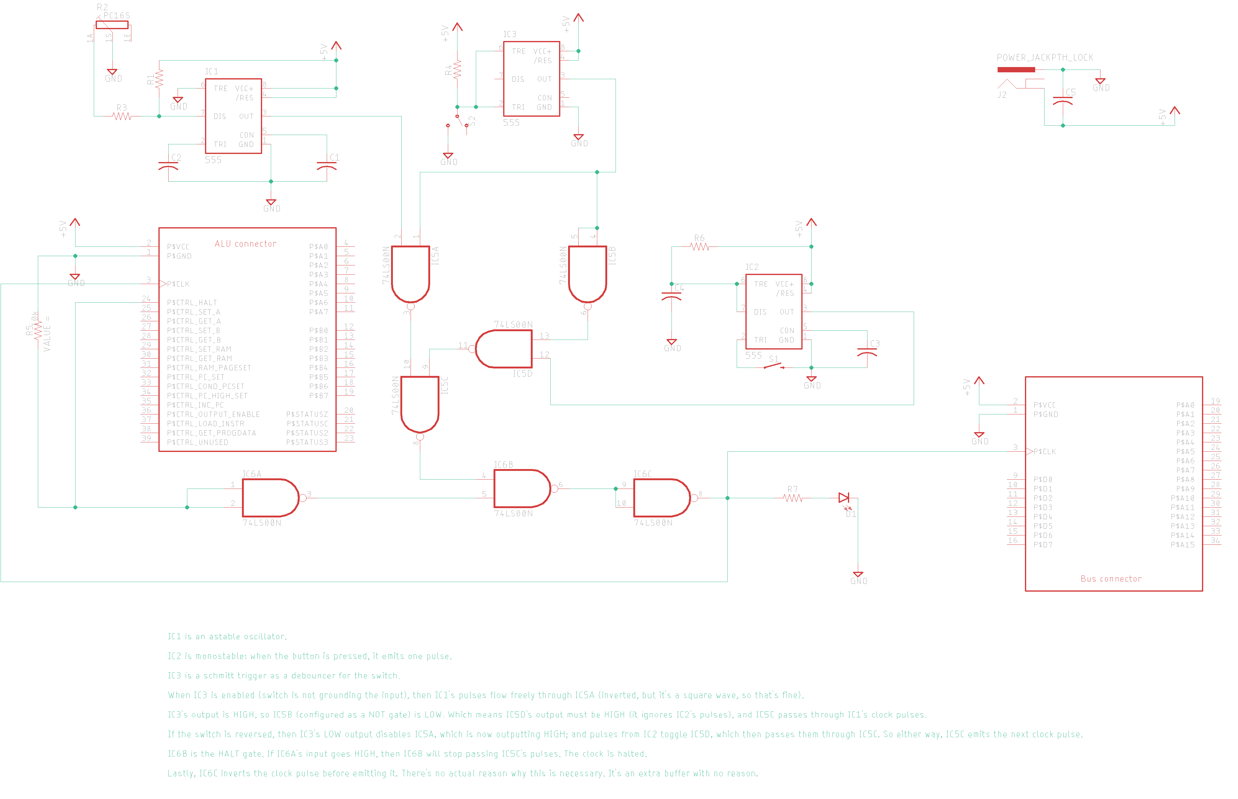
All of that's glued together with some NAND logic: if the switch is open, then the astable 555 clock runs free. And if it's closed, then the clock is just pulses from the button.
One last addition: eventually I want the CPU to be able to HALT itself. So I need a halt control, which will run through another NAND gate at the end.
The whole thing looks like this:
Next up is the program counter...
Discussions
Become a Hackaday.io Member
Create an account to leave a comment. Already have an account? Log In.