 SUF
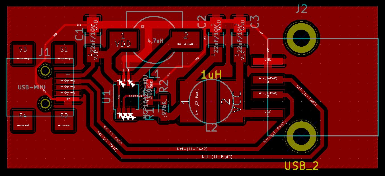
SUFCreated a second board, now with the corrected USB connector pinout:
And I built it:
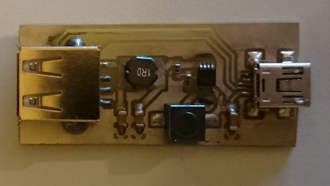
The problems started here.
The first thing, I wanted to test it. To test it it is not enough to connect it to some random USB source. I wanted a variable source.
I've a lab supply, but it has no USB out. As I didn't wanted to cut any USB cables, I designed and built this small "tool":
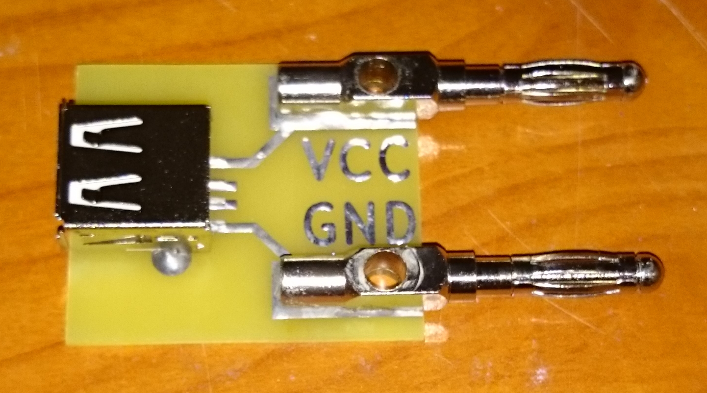
After this the testing went to a complete disaster.
1. It was working from ~2V to 4.3V correctly, but when I went above 4.3V the output voltage just went above 5V. I was thinking this can be the result of miss of the minimal load, what usually required. So I setup the circuit with some (~50mA) load:
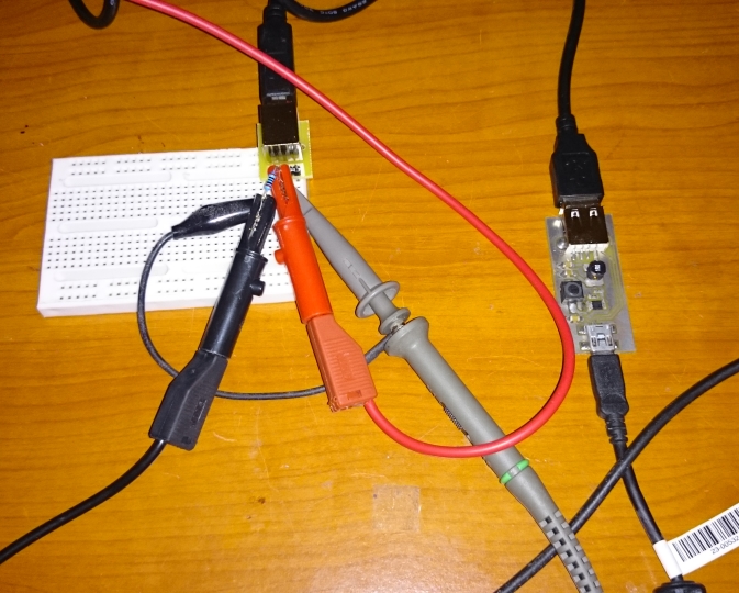
Testing..
At 2.0V:
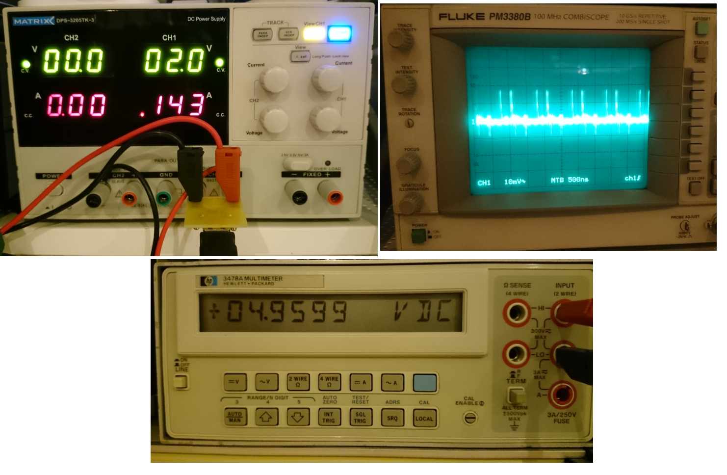
Looks good
At 4.3V:

Still looks good
At 4.4V:
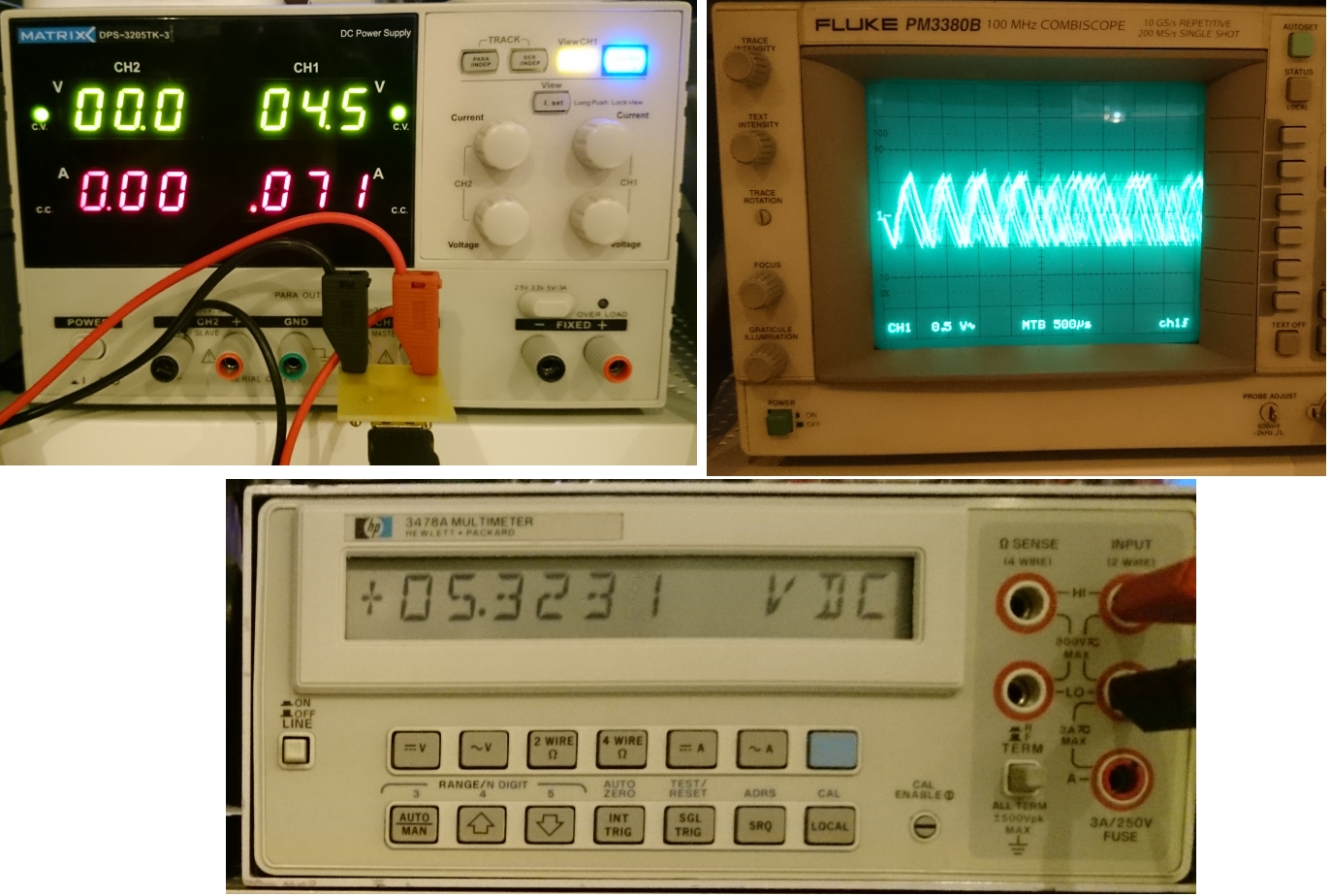
Not so good anymore. :-(
In addition, if I change the voltage, sometimes the whole circuit gets unstable. So the result clearly useless.
I've possible explanations to the things above:
- I've a crap layout - I'll try to enhance it in the next version
- I've some sort circuit(-is) things in my build. I can admit that using solid groundplane around the surface mount inductors without insulating solder mask wasn't my best idea
- The boost regulator is unable to handle the >4.3V in 5V out situation even if the datasheet just said Vout>Vin as a requirement
Here are the possible solution for the next try:
- Create a new board, with different layout and definitely with a cutout in the groundplane around the inductors
- Use the pass trough capability of the chip (this will require some kind of external comparator)
- Use a different (buck-boost or SEPIC) circuit - I may try the LM2621 what I ordered already for one of my other projects
- Keep the current boost converter (rising the output voltage to - let say - 6 volts) and use it as a pre-regulator for an LDO. As It suggested by The Big One.
Discussions
Become a Hackaday.io Member
Create an account to leave a comment. Already have an account? Log In.
....and the bodger in me would be tempted to throw a diode into the input path and call it a wrap. :-)
Are you sure? yes | no
Probably my English is not good enough, but I didn't got it. :-(
Are you sure? yes | no
Sorry SUF, "bodge" is an English-English (not American) slang word for doing something very badly (my normal sort of work :-)). I meant that if the regulation drifts off when you get within about 0.7v (suspiciously close to a base-emitter junction voltage) then I would be tempted to add another junction (a diode) to prevent the input voltage getting that high.
I enjoyed reading your project notes, by the way. Please keep them coming!
Are you sure? yes | no
Ok, now I got it. :-)
Thank you for your compliment. :-) I try to write my project logs as much I've time. On this project and on the others. Most of the time I'm doing more work on the project than I've time to write about it. BTW, some of the things are appear on my blog and not here:
http://pakahuszar.blogspot.com
Are you sure? yes | no
The diode drop in the input would get rid of the 4.8V... It come with reverse polarity protection! :)
I'll probably need to use urban dictionary on that word...
Are you sure? yes | no
5V/5.2V = 96% for the LDO, so really not going to affect the efficiency by much.
Are you sure? yes | no
Yes, but I highly doubt that I can keep the boost regulator stable at 5.2V out with let say 4.8V input.
Are you sure? yes | no
Might want to try a different type of boost controller. The MCP part is PWM based, so it run at a fixed frequency and regulate by varying duty cycle. A hysteretic boost regulator such as the LM2621 only turns on the boosting when it see the voltage drops below a certain threshold, so it might work here.
FYI: Linear Tech SMPS layout guide: http://cds.linear.com/docs/en/application-note/an139f.pdf
Are you sure? yes | no
Thanks, I may try a different one. The LM2621 is a good candidate because I've a few lying around.
I'll check the appnote.
Are you sure? yes | no
I don't think it is a layout issue, but here is what I see.
On the layout - the trick for SMPS design is to understand the current loop(s). This is something very useful for SMPS, EMC and high speed designs - always under the flow of AC current, return paths etc and minimize the area between them. This will improve on things like EMC, signal integrity etc.
The current flows from the C2 via U1 to L1 to output cap and back from ground to C2. There is a secondary path from Ground to U1 to L1 to C2 back to ground. So better location of C2 is on the left hand side of U1, (ideally under U1 and make connections to power and Gnd.) C1 and C2 should be side by side to minimize the Ground connection.
I think the problem might be there is a minimum on time (i.e. duty cycle) on the boost converter, so it can't get below that and that's why your output voltage is too high when you get above a certain point. A heavier load might help or you design the boost for 5.2V or so and let a LDO regulate the output down to 5V. This helps with the noise issues too.
SEPIC would work too. Just be aware that the efficiency is a bit lower and there can be some stability issues. Ideally you want one that is design for SEPIC.
Are you sure? yes | no
Thank you,
This is really valuable information, I'll definitely use for the next round. The minimum on time is out of my hands, as I can't predict the input voltage and the load current as these factors can be changed according to the usage situation.
I'll try to make some efficiency calculations to decide between the SEPIC and the Boost+LDO. I feel that the later better suits into the requirement profile because of the less noise, so if there is not to much efficiency drawback there, I'll use this.
SUF
Are you sure? yes | no