The Bluetooth modules I used are the very common CSR Serial to Bluetooth modules. I bought them from dealextreme. Sadly I realized while waiting for my order to arrive that they were HC-06 modules (slave only) and not HC-05 (Selectable between slave and master) So browsing the web to find out more about the modules, I found all the info I needed right here: HC-05 / HC-06 After finding an old windows xp computer that had a parallel port, I managed to flash the HC-05 firmware provided by Byron. I will not cover the steps to change your firmware to HC-06, because all info can be found on Byron's blog.
Now the board on which the modules came are layed out for the HC-06 pinout which differs a bit from the HC-05 pinout (all this info on Byron's site). So once flashed, the LED no longer works and the KEY pin required to place the module in AT mode is not wired to the correct pin. A little modification is needed to get the KEY pin working. You need to get the module in AT mode , and send a few commands to prepare the module the way you want to, ex. setting password, module name, baud rate, etc. Unless you plan to have the module change between master and slave on the fly, or change other more important settings, you will only need to get into AT mode once. Also the module's TX pin has a diode in series, bringing the line's voltage to only 2.6v and that wasn't enough to trigger the AVR which is running 5v. This diode was remove and replaced with a wire to get the 3.3v volt output, which is enough to drive the AVR. These boards can accept 5v as VCC , but it is not recommended to drive the RX line directly at 5v. A simple resistor bridge is used to keep the RX pin at 3.3v .
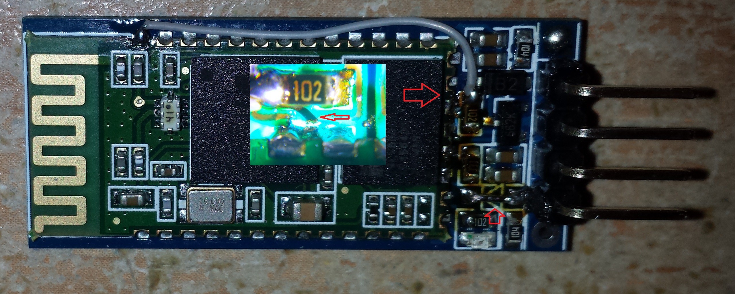
The new KEY pin is now pin # 34 where the gray wire is soldered. I cut the trace after the resistor and wired it to the key pin on the module, this way I could use the KEY from the breakout board. Also notice the diode at the bottom was removed and replaced with a wire. I'm sure a wire directly from pin 34 would of worked just as well, but this gives a more permanent solution. The microscope shot I pasted on top of the module is the cut trace from the 1k resistor.
Once the modifications to the boards are done, they now have to be setup properly. My code is divided in 3 parts under main(), selectable by a definition. Define either SETUP , SLAVE or MASTER in order to compile the board. The Bluetooth modules are setup using the keypad box , using the SETUP compilation.
Discussions
Become a Hackaday.io Member
Create an account to leave a comment. Already have an account? Log In.