 Anderson Antunes
Concept
The idea of creating volumetric circuits (term derived from volumetric displays, 3D matrices) came from an old will that I have to build and computer from scratch. I thought of doing something big, not just pure functional, something, artistic and eye candy, something that catches attention and inspire people to learn about how computers work, and how to build their owns. But for this to happen there is a lot of planning, designing and prototypes involved, this project is the first step.
First Concept Video
The software
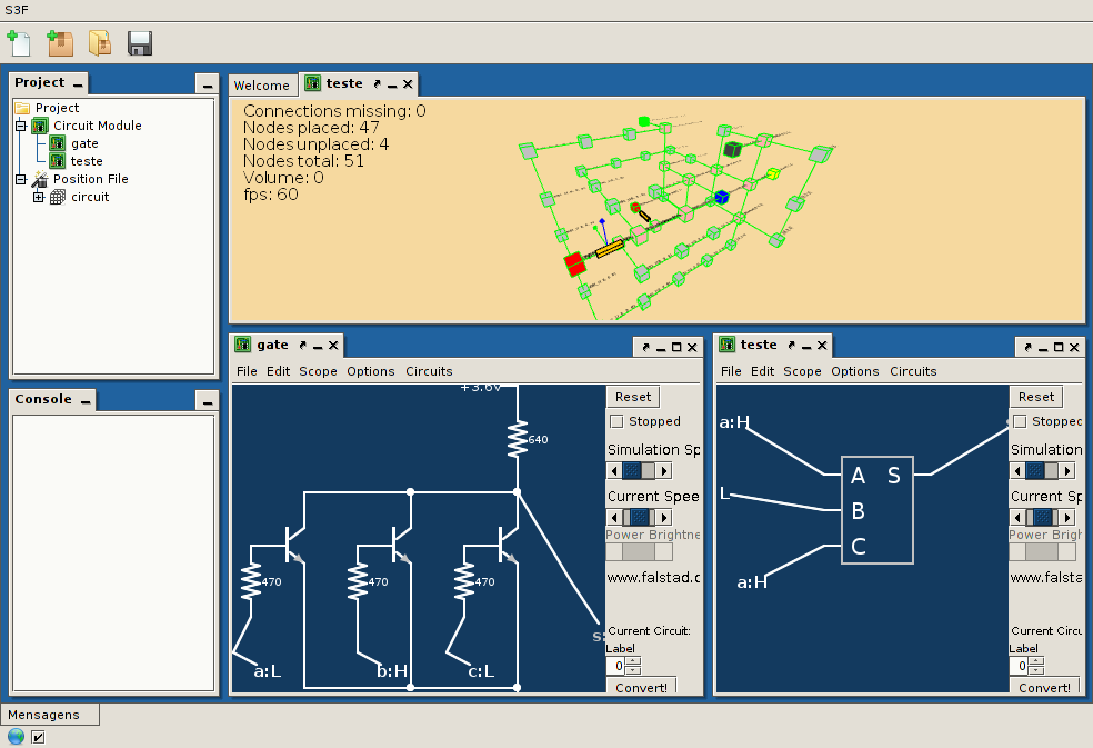
Positioning the electronic components manually will be impractical or even impossible, so an open source software called Pyrite is in development, it is made in Java and contains an schematic editor/simulator and a 3D visualization tool for control the graph algorithms and help in the build process.
Pyrite uses the S3F framework allowing it to be extensible and flexible. Plugins containing new algorithms, view modes and file type support will be easy to develop and share (after I finish writing the documentation).
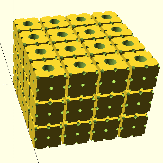
Creating volumetric circuits in Pyrite
Using Pyrite will be simple, and in 5 easy steps you'll have an fully working 3D interactive environment for your creations!
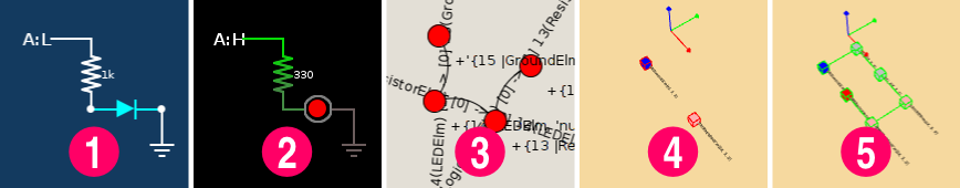
- Create the circuit diagram
- Simulate and check for errors
- Convert the circuit diagram in a graph
- Place start nodes
- Chose the parameters and run the folding algorithm
Future applications
This project can be extended to allow creation of:
- Organized high frequenciy point-to-point circuits
- Simple circuits without PCB
- Modular volumetric circuits
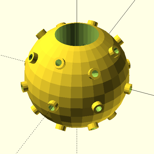
- 3D printing/placing components
- Lego-like electronic toys
- And more!
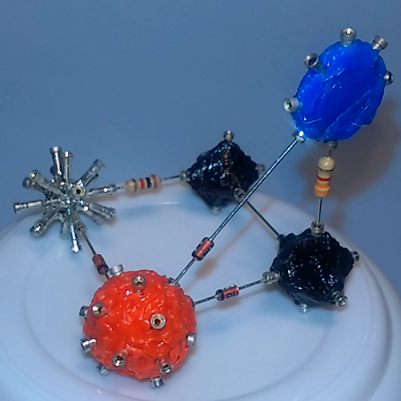
System design
The system consists of an Arduino doing the digital interfacing between the volumetric discrete 1-bit arithmetic logic unit and a computer. The PC requests multiple arithmetic/logic operations and waits for the response, the message can be an single bit operation or an more complex operation which will be broken into small steps by the Arduino. The information to be processed can come from an testing software, virtual machine, or even over the internet.
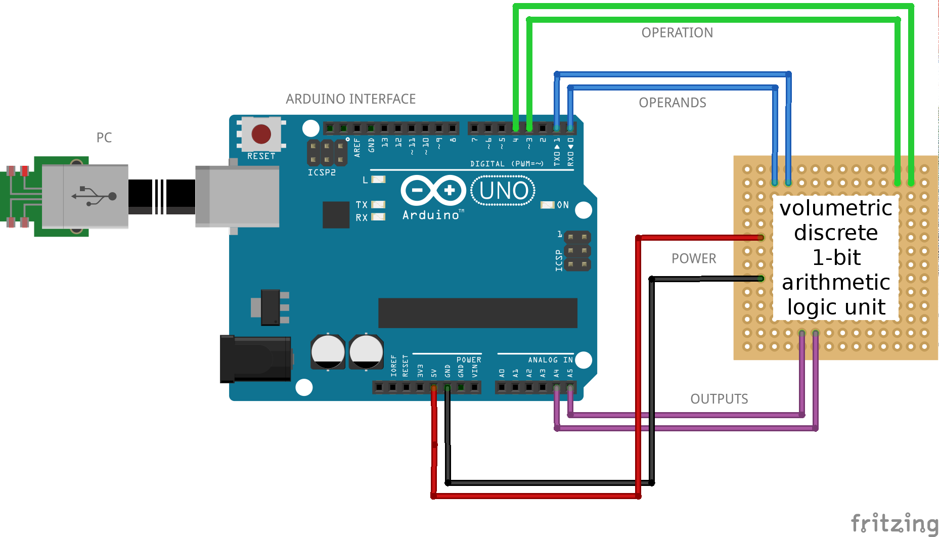
This configuration along with some other instruments allows several testing procedures to be performed, resulting in valuable data about the maximum frequency supported by the ALU, interference, construction errors, and more.
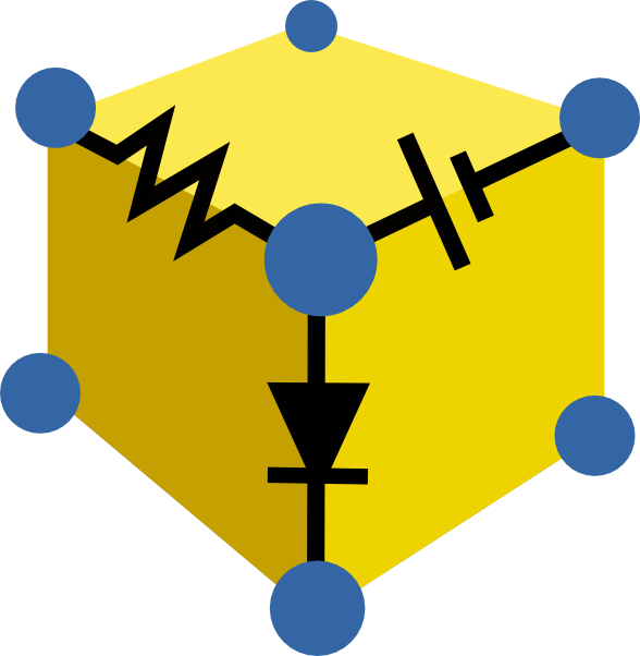
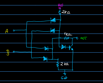
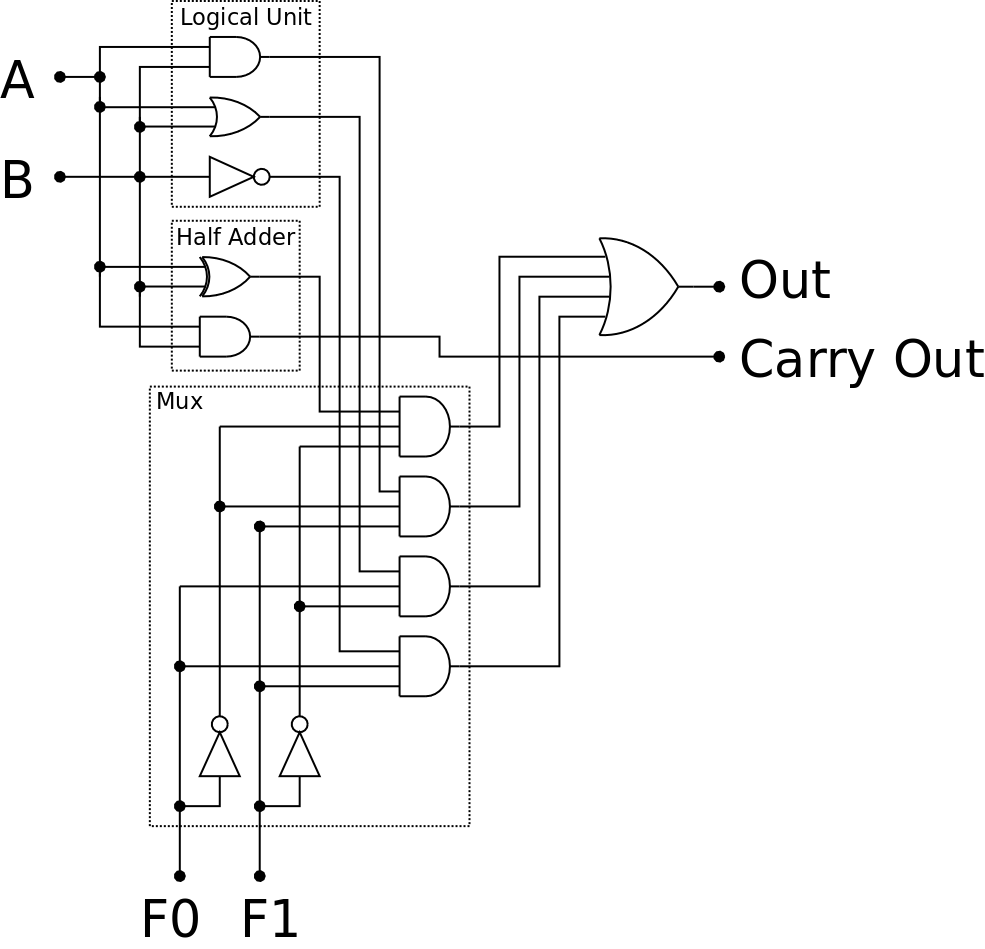
Finally the ALU design, it can perform 4 diferent operations (AND, OR, invert B, XOR, and SUM) and consists of two 2-input AND gates, one 2-input OR gate, tree logic inverters, one XOR gate, four 3-input AND gates, and a 4-input OR gate.

The majority of the logic gates will be constructed with simple resistor-transistor logic, as follows.
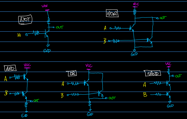
The only exception is the XOR gate, which is will be a diode-transistor-like construction.
Inspired by...
Harry Porter's Relay Computer - http://web.cecs.pdx.edu/~harry/Relay/
Rory Mangles (TIM computers) - http://www.northdownfarm.co.uk/rory/tim/
Esperantanaso - https://www.youtube.com/user/Esperantanaso
Nablaman - https://www.youtube.com/user/nablaman
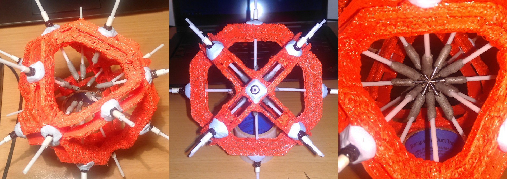

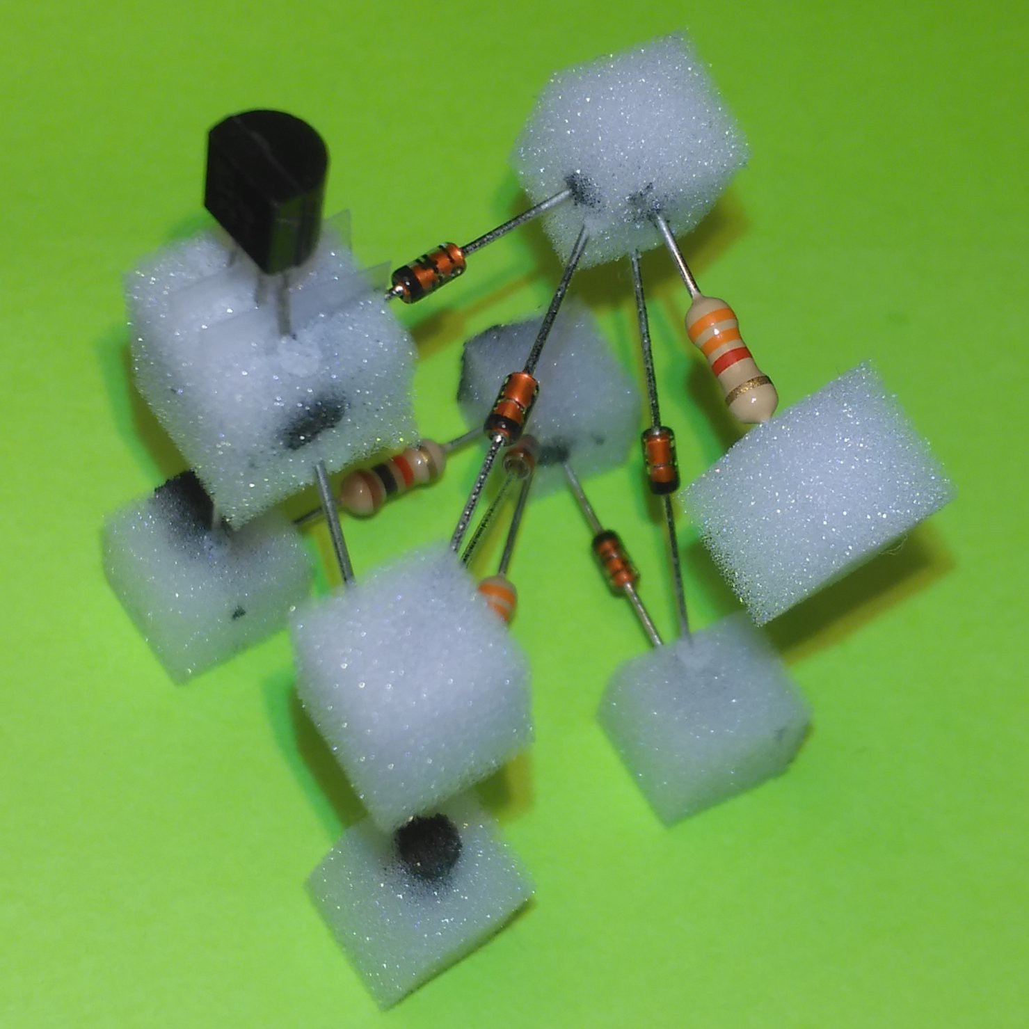
 I tried a cheap alternative to the 3D printed parts: Melamine foam (magic sponge), due its density and stability. I assembled the circuit together and used a syringe with a needle to inject some wire glue in the sponge cubes.
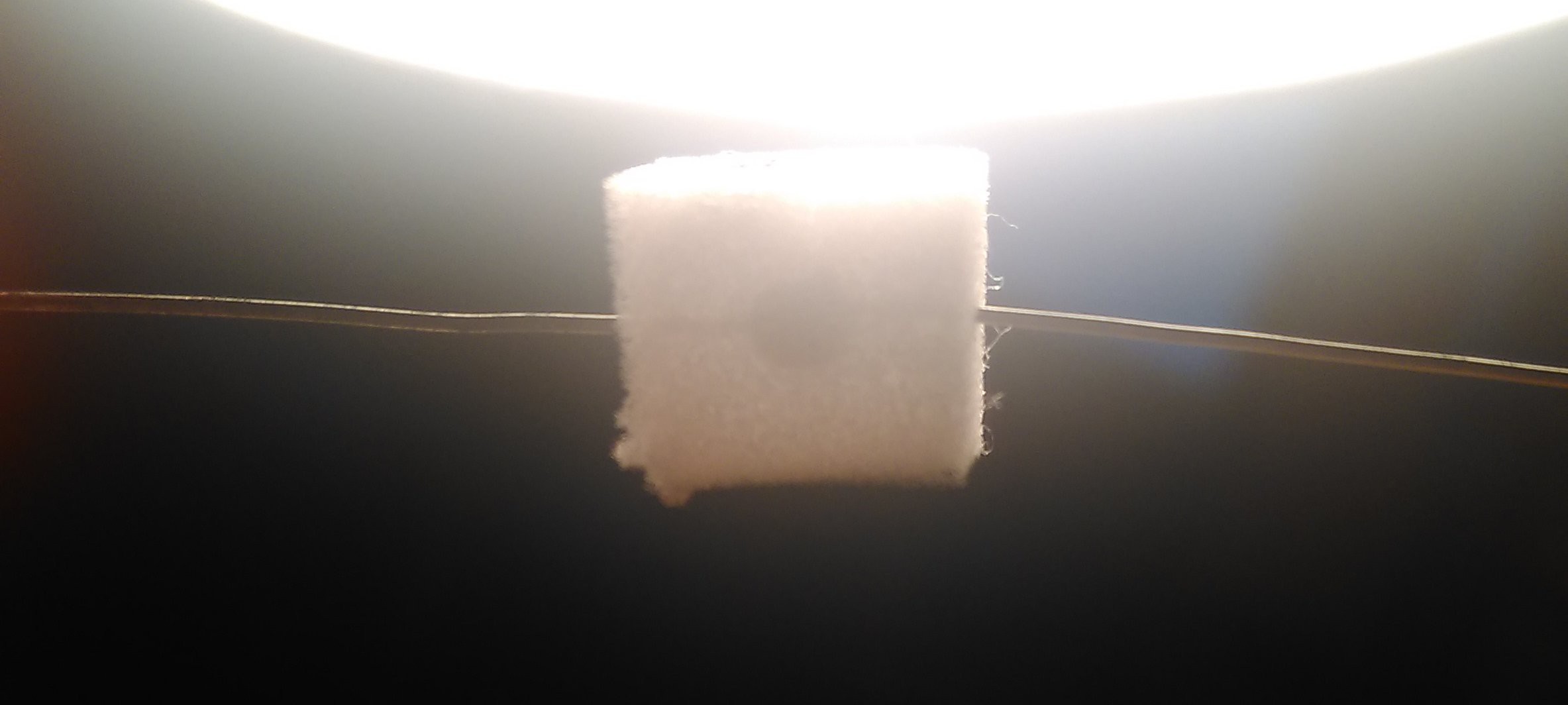


 Ramón Calvo
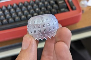
 Sam Ettinger
 Mike
Mike
 AngelLM
Hi,
first i love this idea. Why? Because I love such things... I love going out for a walk with the dog and imagine solutions where different technologies come together and form something new.
I was thinking of how one can do a Circuit-3D-Printer and this was my "Chain-of-Conclusions"
1. Why must it be a two dimensional design?
2. We don't need a PCB... so we don't need traces
3. If components can be aligned somehow in 3D space the can be just glued together
4. If we are able to place and glue components in 3D space, we need a new ECAD tool and maybe new "3D components".
And today i saw your project and thought... cool somebody did it, a 3D ECAD tool!
Now we need somebody to build a 3D place and (conductive)-glue machine.
I can think of a combination of a Z-Platform and those tiny micro-robots the SRI has developed
Go on!