 willbaden
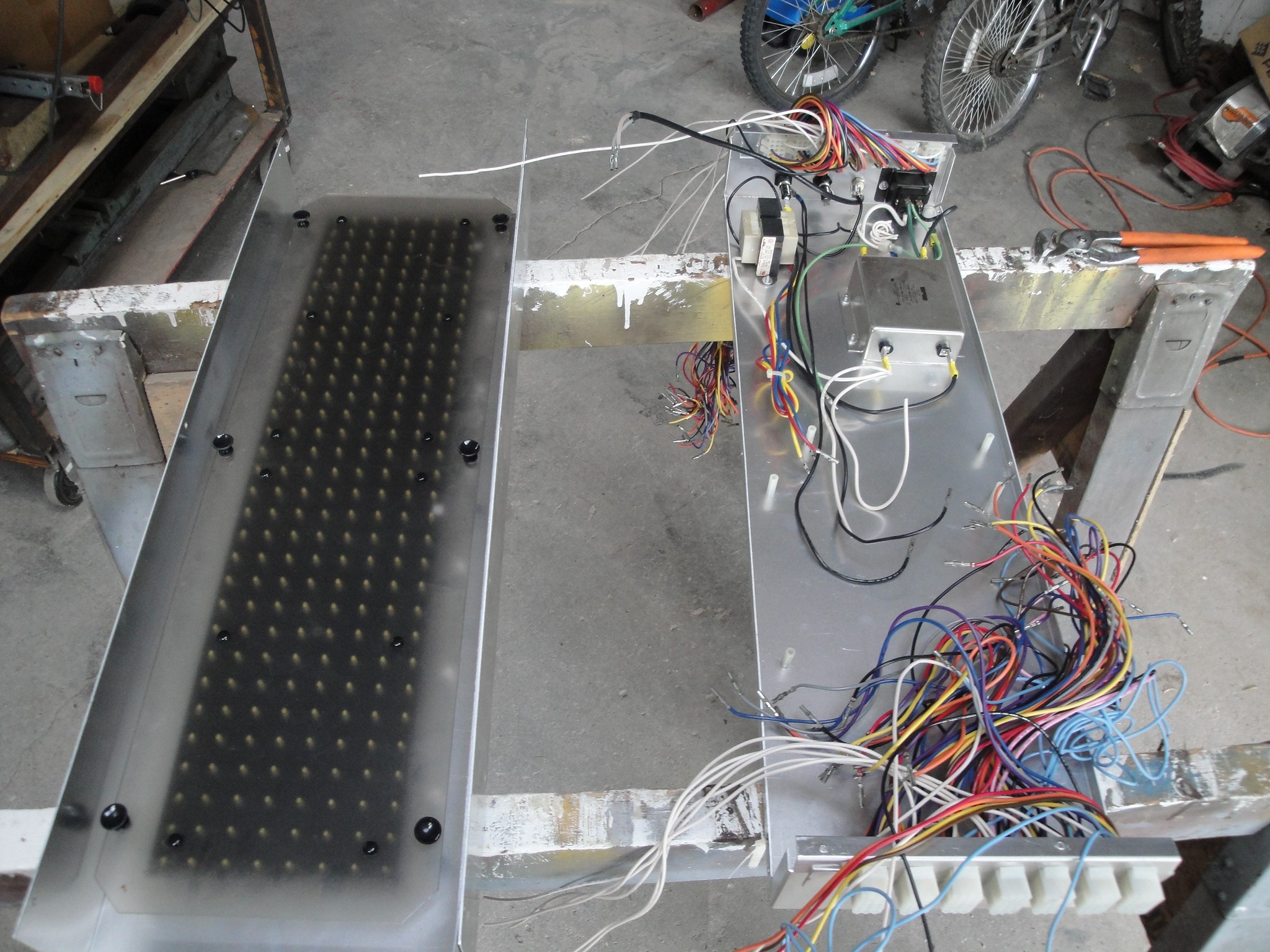
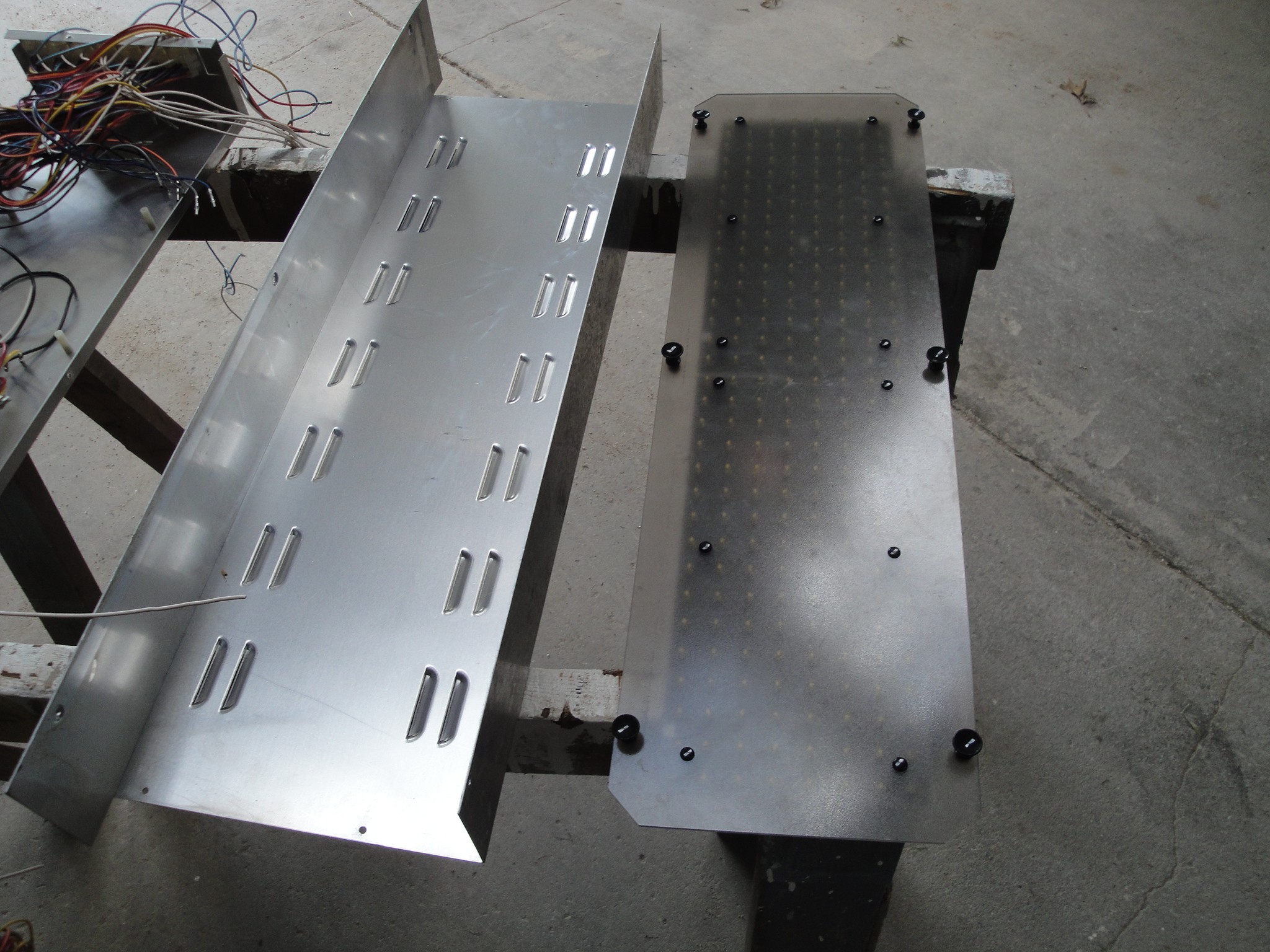
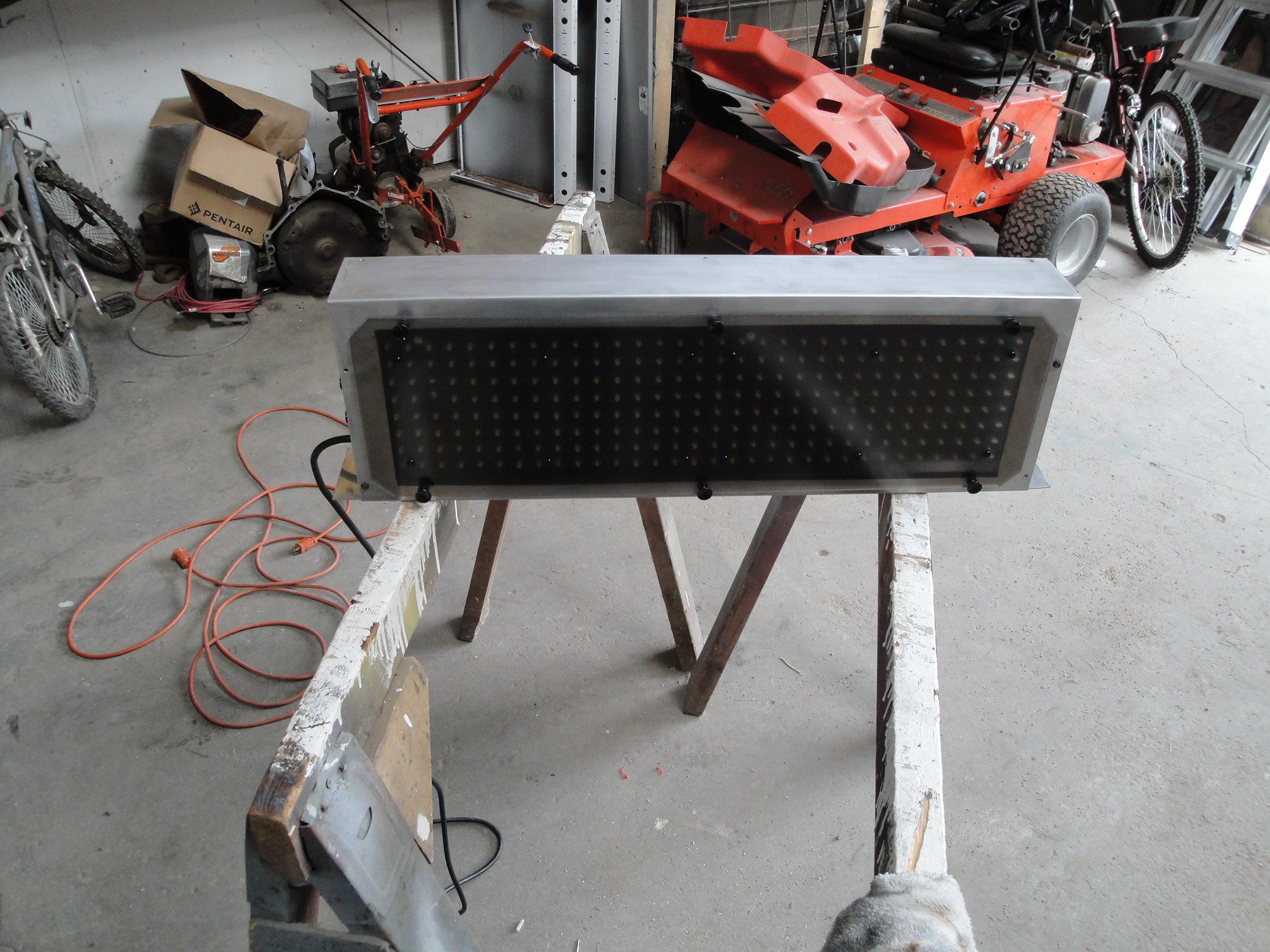
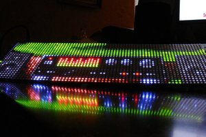
Using an old Fairplay Scoreboard LED matrix to display scrolling messages (one of which was also for the kiddos birthday, scrolling "HAPPY BIRTHDAY")
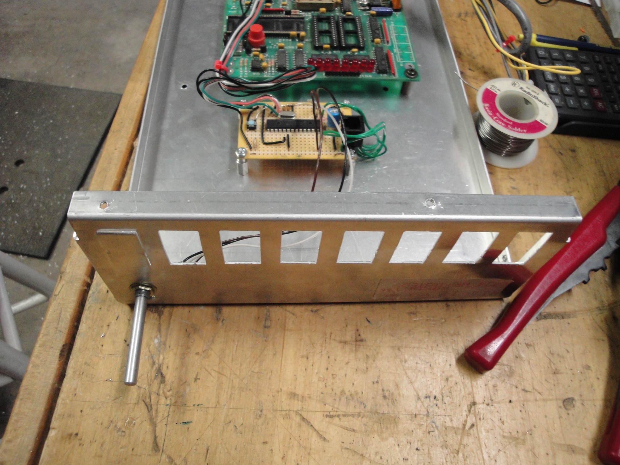
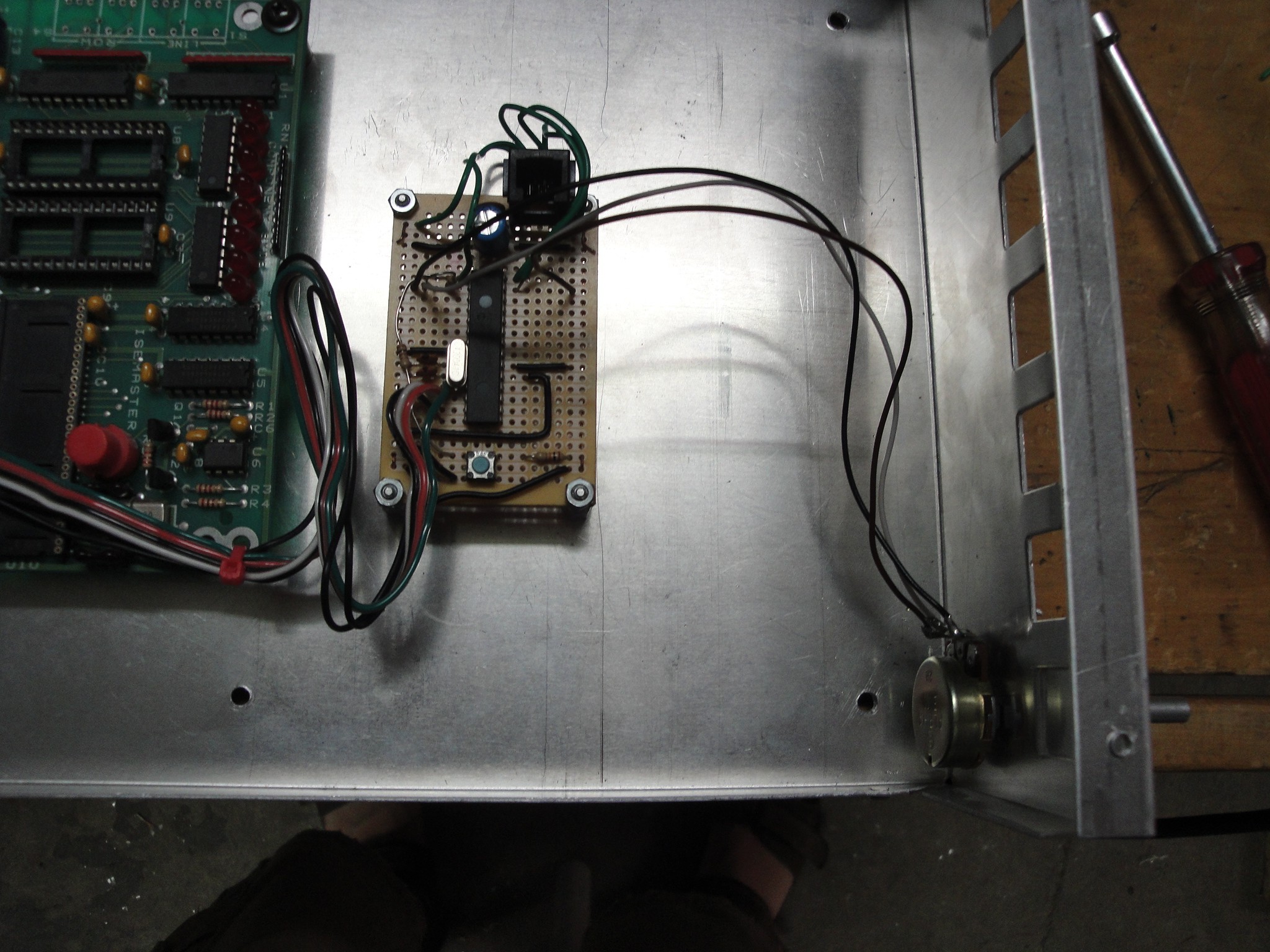
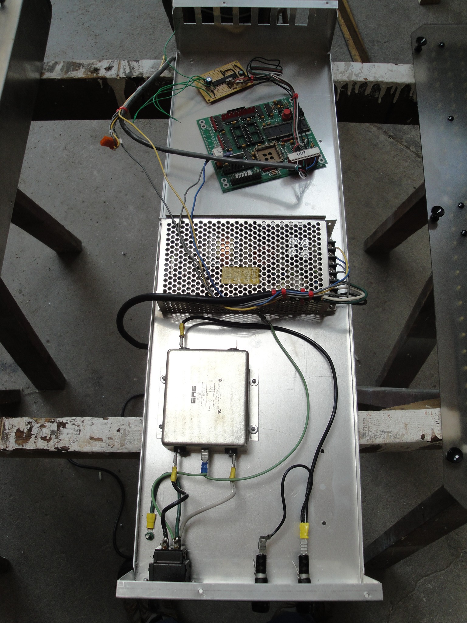
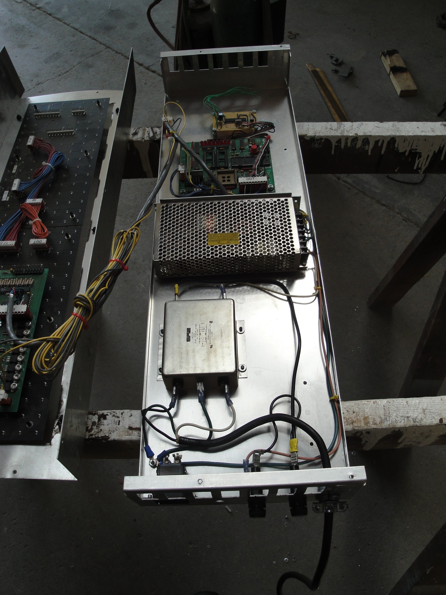
A PIC 16F870 was used for the controller. The factory controller was ditched as I was unsure how to use/program it. I still used the factory board for the 5V power supply (seems kind of silly to have the large board just as a 5V power source, but it worked)
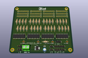
To reverse engineer the LED driver board, I looked into the datasheets of the populated board and eventually came up with a shift register and clock design. (being it has been a few years since I actually reversed engineered it, I may get some of the facts mixed up, so bare with me).
From what I remember there is clock timing that will have to be seen by the board or it will error out and a red LED will light up (more or less a visual indicator to let the user know that there is a clock signal being sent to the board). But once that stays within its specs, the green LED will light up letting me know that I had the timing right.
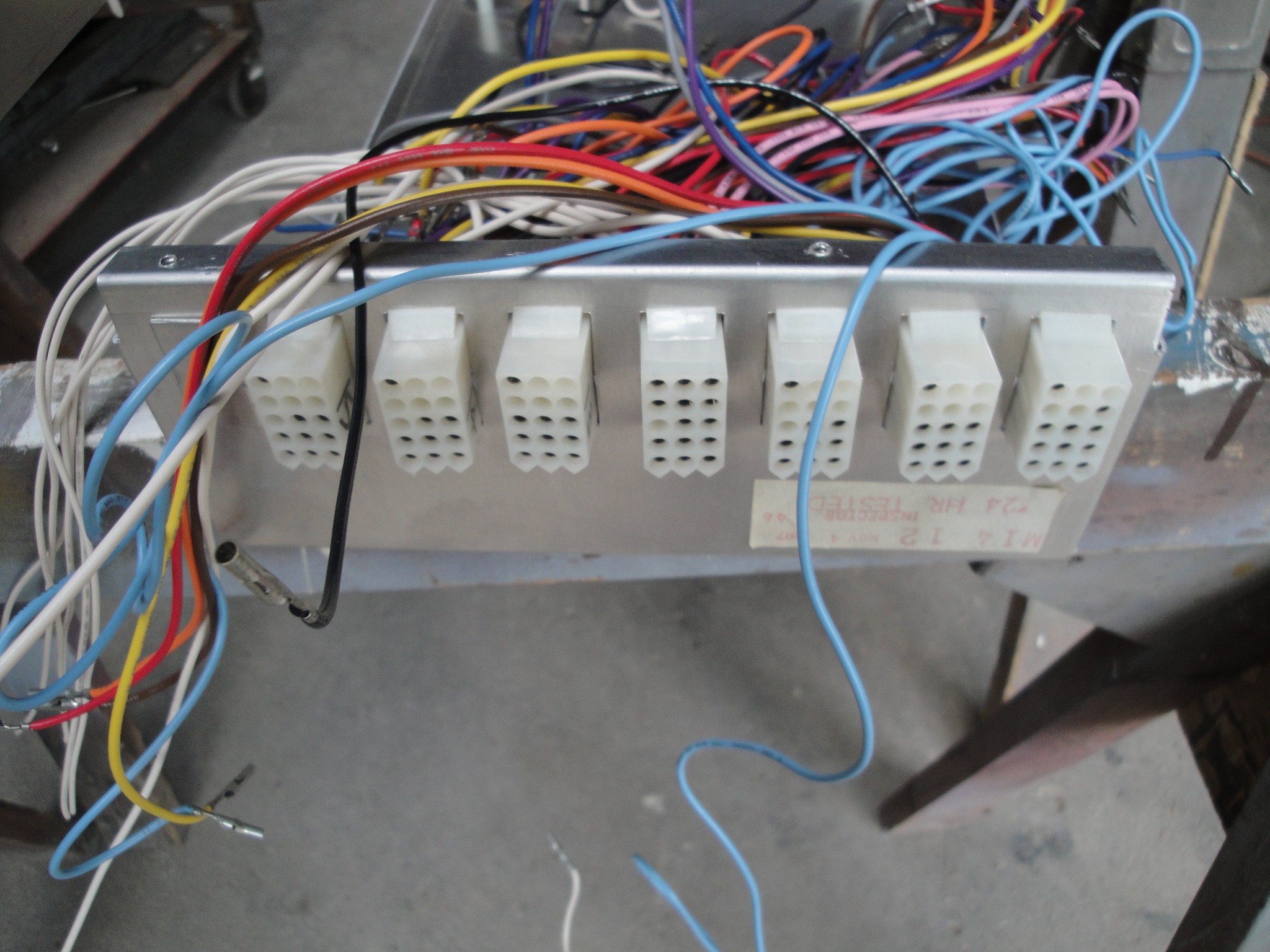
There are 3 clock lines, two for the two separate boards column shift register clock and one for the row select clock.
There is then a single data line to send the LED light sequence for the selected row. This is sent to a shift register and then displayed.
Sticking to what I am comfortable with I used asm and timer interrupts.
I am throwing around the idea of making a serial interface to quickly change the scrolling text. Right now I have to reprogram the code to change what text I want to scroll. Currently it is set to "2 TICKETS = 1 PLAY".
 Ian Hanschen
 Ken Yap
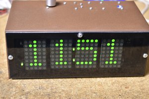
 Bharbour
See amazing LED project here: http://kck.st/1Oi2sHC
Simply and affordable...