 RaptorTech
The Hackaday Prize Entry
Entry video:
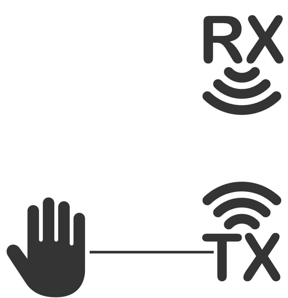
Connected
- To user
- To radio system
- To plane
- (To computer for graphical data output)
Goals
- Make piloting model aircraft more intuitive and enjoyable
- Simplify the learning process for flying UAVs
- Easy to build and modify
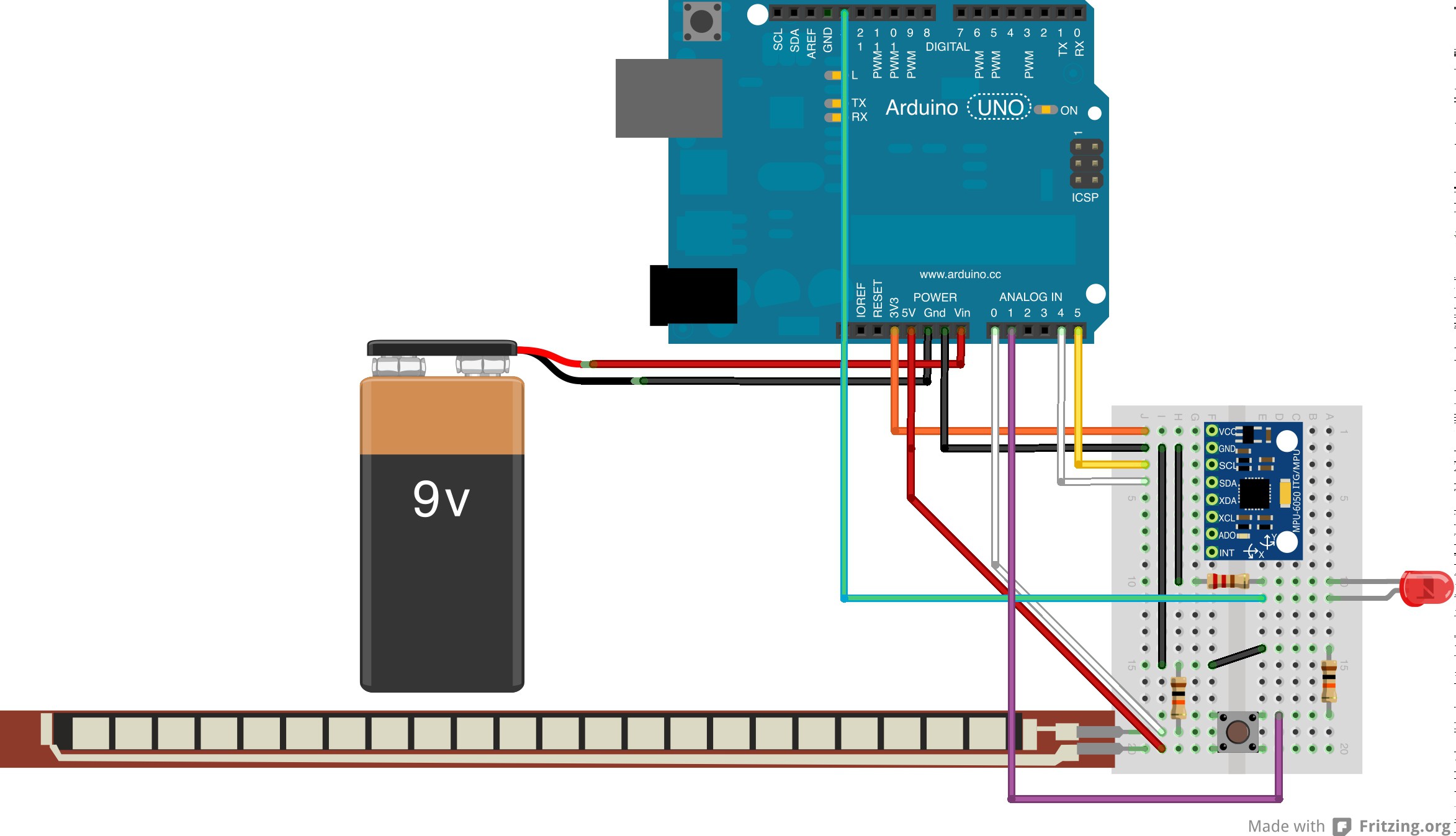
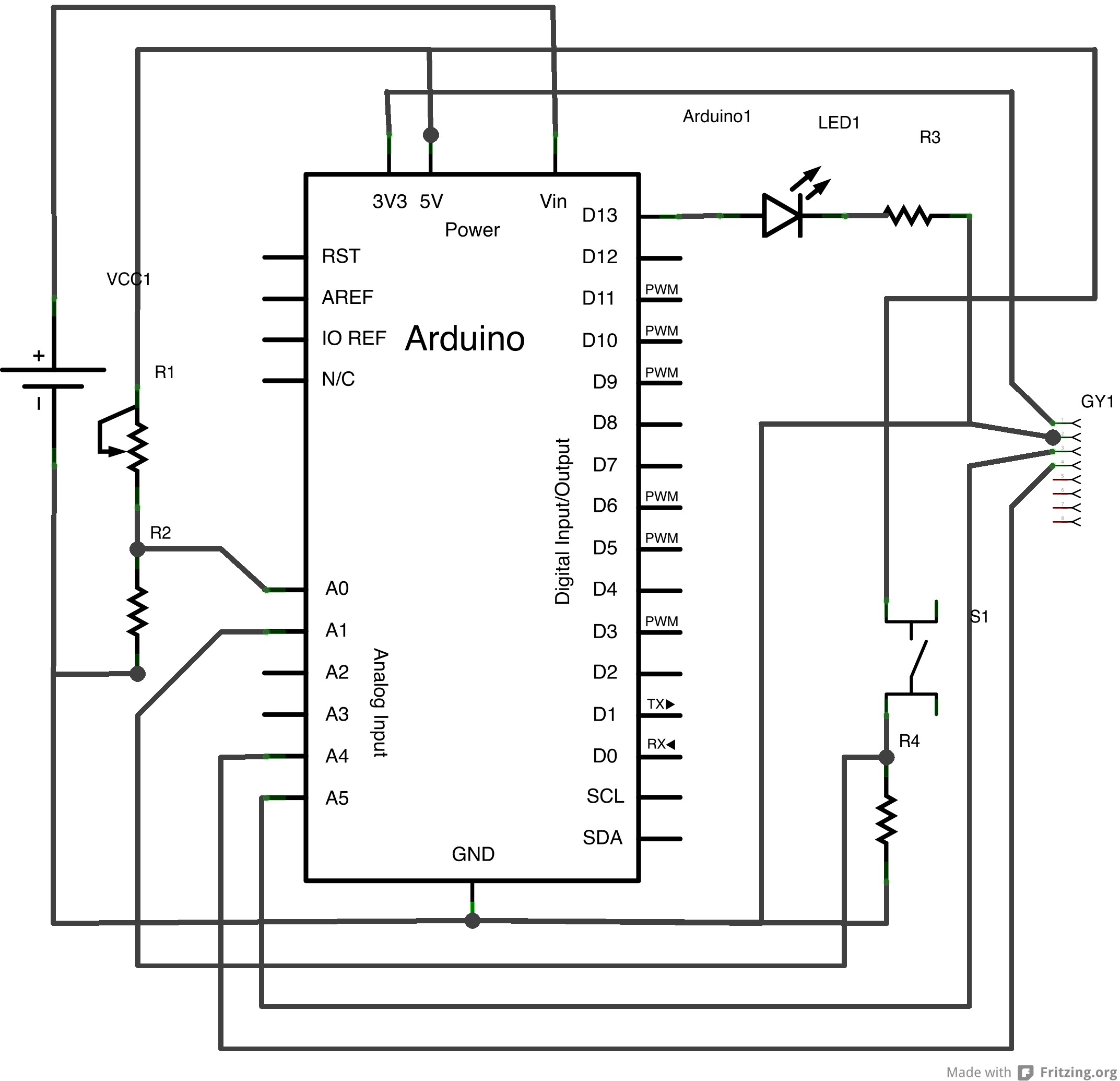
System Diagram:
Origins
Have you ever noticed that nearly all controllers for are simply buttons, switches and joysticks? Clearly, the button and joysticks combo is a proven and effective method of controlling complex systems, but is it the only one?
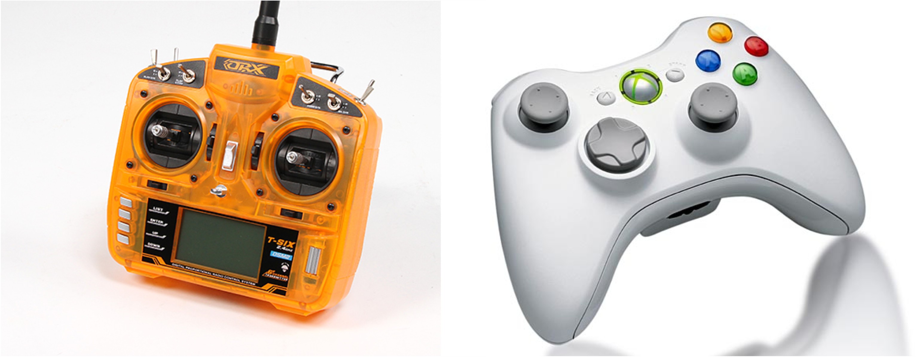
I was questioning this when considering how to teach people to fly model aircraft. I had noticed a trend in my pupils' ability to pick up the new skill: those with video game experience were much quicker to pick up piloting, while those who had not spent time with an XBox or a PlayStation struggled more to adapt to the control system. This indicated to me that the joysticks/buttons/switches control setup does not come naturally to everyone, and that in order to master these controls, extensive practice is necessary.
I decided that I wanted to develop an alternative to the ubiquitous joysticks/buttons/switches to allow people to pick up flying more quickly and more easily, and ultimately control model aircraft more precisely.
What first came to mind was an idea I had a few years back for controlling a robotic arm for Science Olympiad. To control this arm, I wanted to build a smaller version of the arm, which the operator could position, and the full size arm would mimic the smaller arm. This would allow for precise and intuitive control of the otherwise unwieldy machine.
The concept of a "voodoo" style controller in which the pilot would manipulate a miniature model to control the real plane seemed promising, but I wanted to simplify the control system even more. Why even keep the miniature plane? The person should be able to direct the plane with just hand movements!
... and Manucon was born....
Implementation
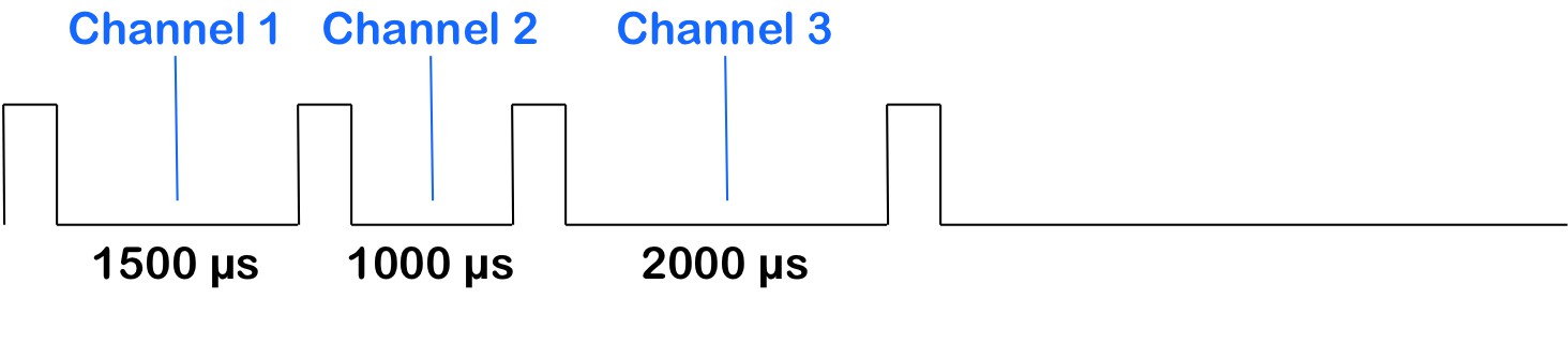
For the first prototype of Manucon, I plan to use a 3 channel airplane, and control roll, pitch and throttle by rolling my hand, pitching my hand, and bending my fingers respectively. The orientation of the hand will correspond to the position of the control surfaces of the model, and therefor approximately the rate of rotation around a given axis. This means that I won't need to "flip" my hand all the way around to perform a loop; simply hold it at an upwards angle and the plane will continue to pitch up.
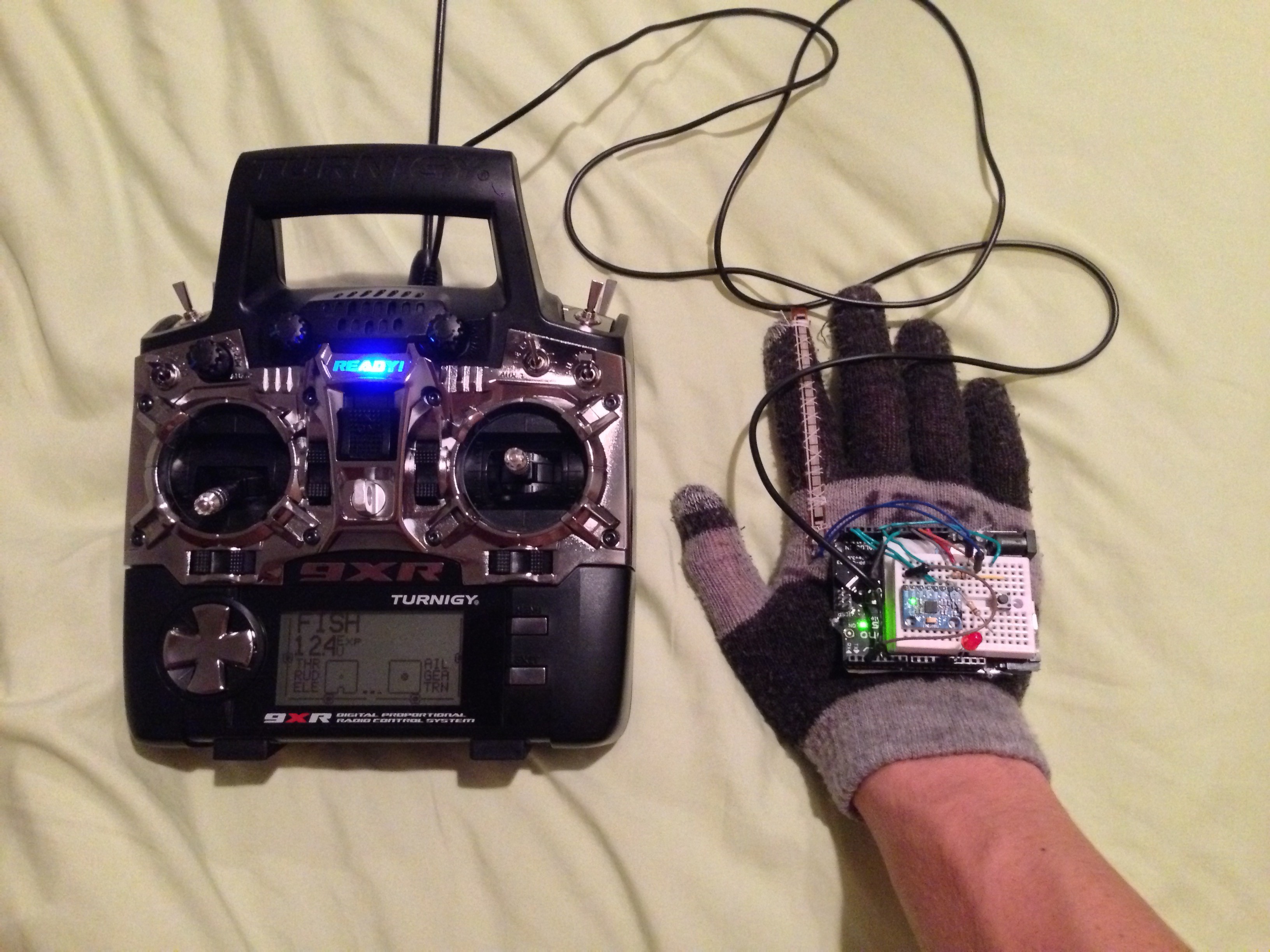
The glove will be controlling the plane through a conventional transmitter set up as a buddy box system. Control of the model will default to the conventional transmitter, but with the flick of a switch, control can be handed over to Manucon.
This means that the data from the Manucon will be sent to the plane through the conventional transmitter. Therefor, I don't have to develop my own radio system to control the model. Also, if the glove fails for some reason mid-flight, the plane can still be controlled by the operator of the transmitter.
Development Goals
- Controls on glove allow for calibration/settings without connecting to the computer.
- Computer software allows user to configure the glove. Settings stored in EEPROM.
- Active yaw axis that does not wander. Possibly means adding Magnetometer.
- PCB containing microcontroller and all buttons/LEDs with headers for the IMU.
- A new glove :)
Progress/Timeline
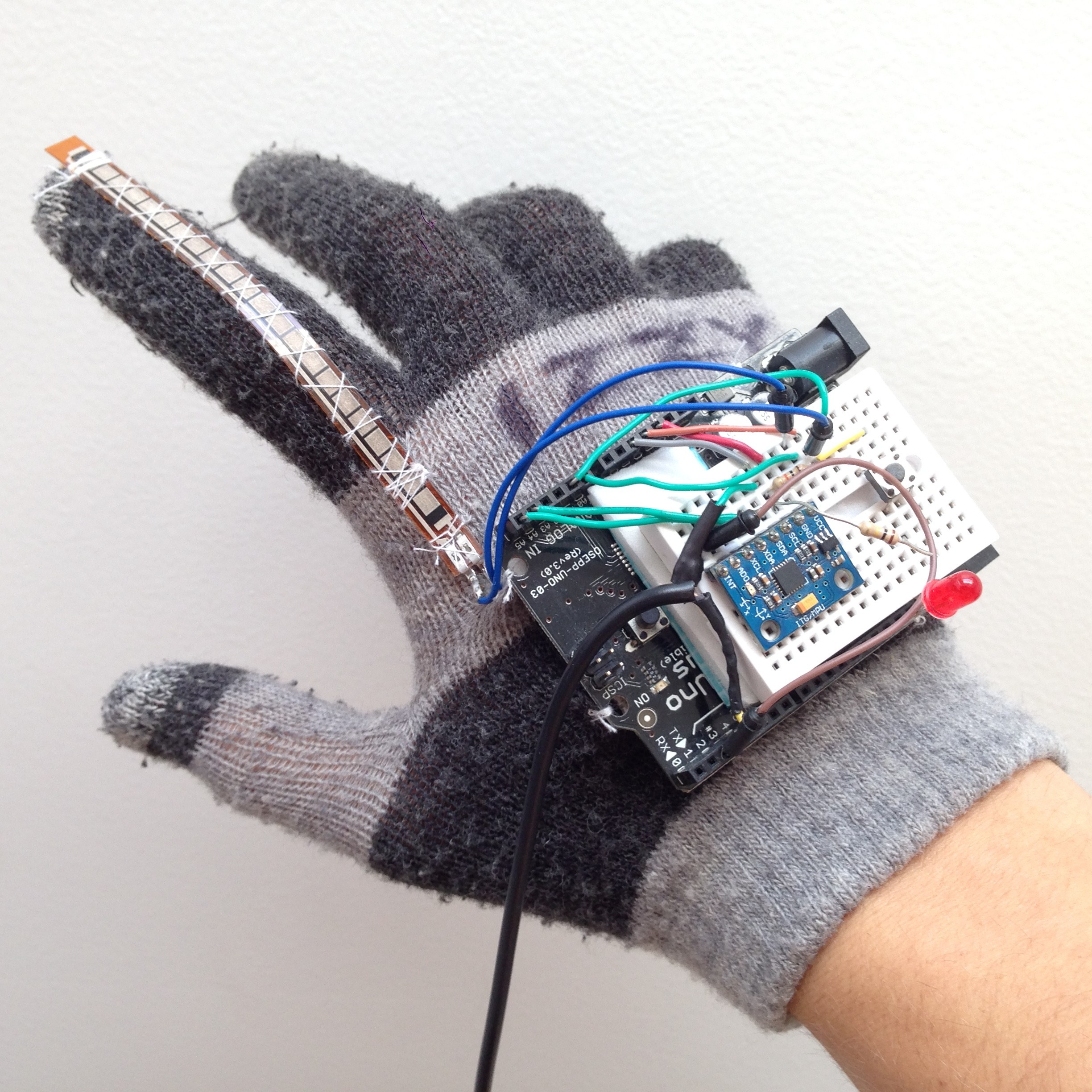
8/12/14 - Selected a glove and sewed on the 10kΩ flex resistor
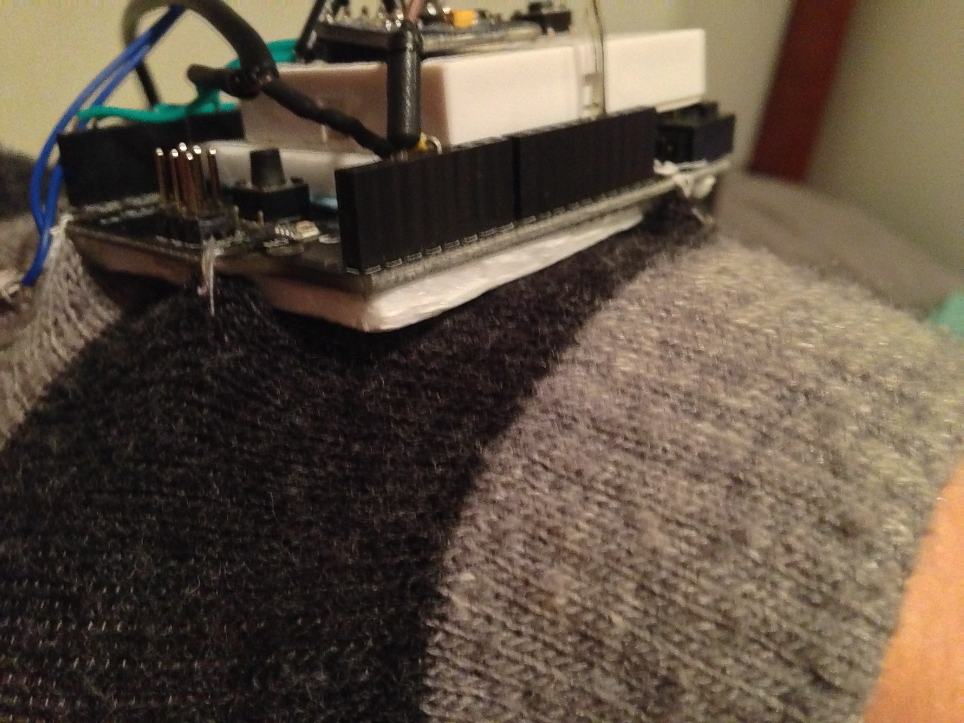
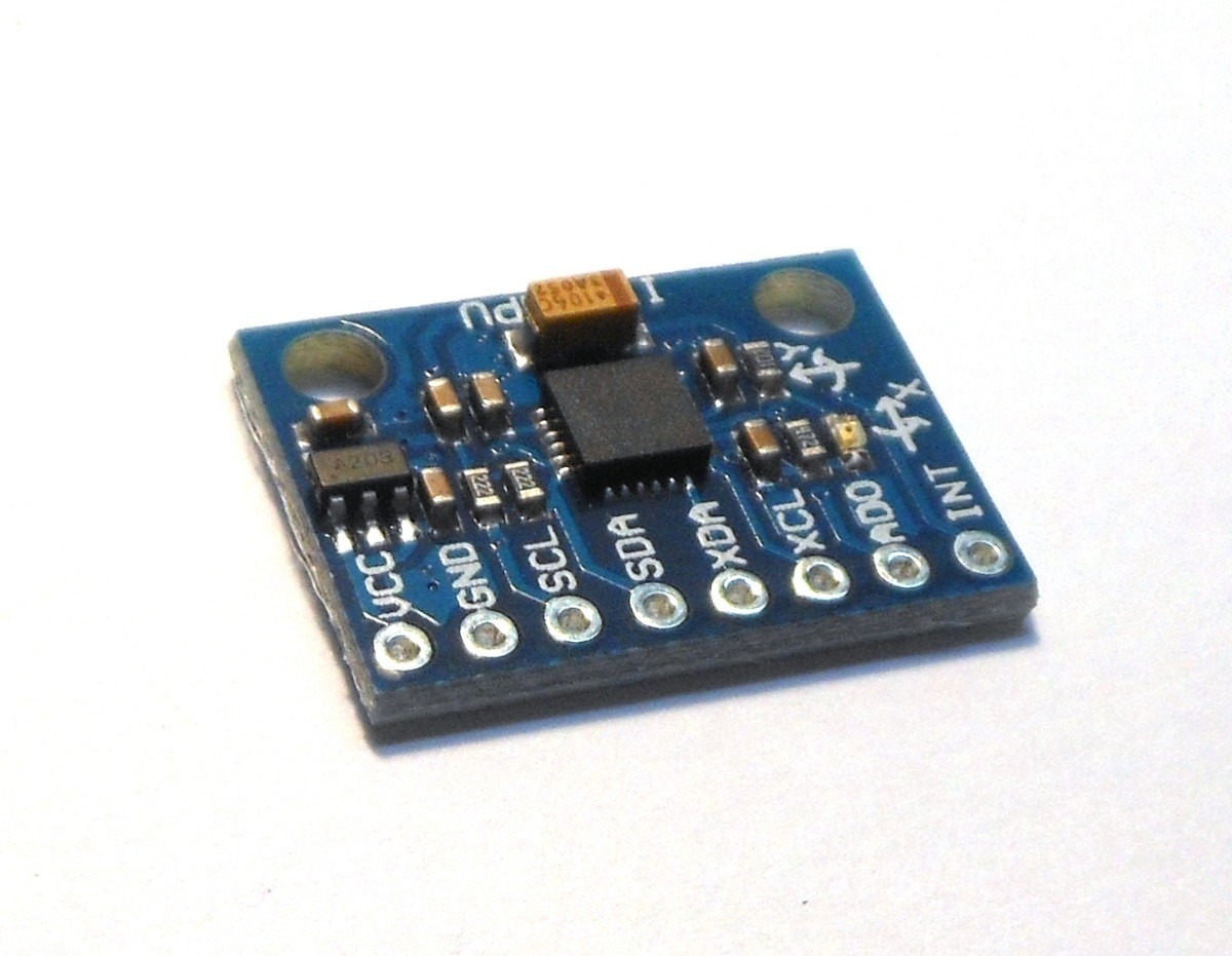
8/13/14 - Sewed the OSSEP Uno R3 microcontroller to the back of the glove with a layer of foam to protect he hand form the headers. Added a small breadboard on top of the OSSEP Uno R3 and wired up the MPU6050 6 axis IMU.
8/14/14 - Wrote Arduino program to pull data from the IMU and combine into absolute orientation using a Kalman filter. Soldered wires to the flex sensor and connected it to the microcontroller.
8/15/14 - Wrote a graphical output in Processing to visualize the data coming from the glove.
8/16/14 - Modified Arduino code to output PPM....
Read more »
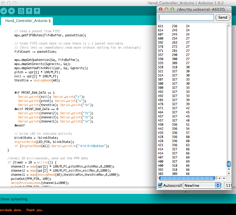 Everything seemed to be working well, but there's only so much you can see from the rapidly scrolling numbers.
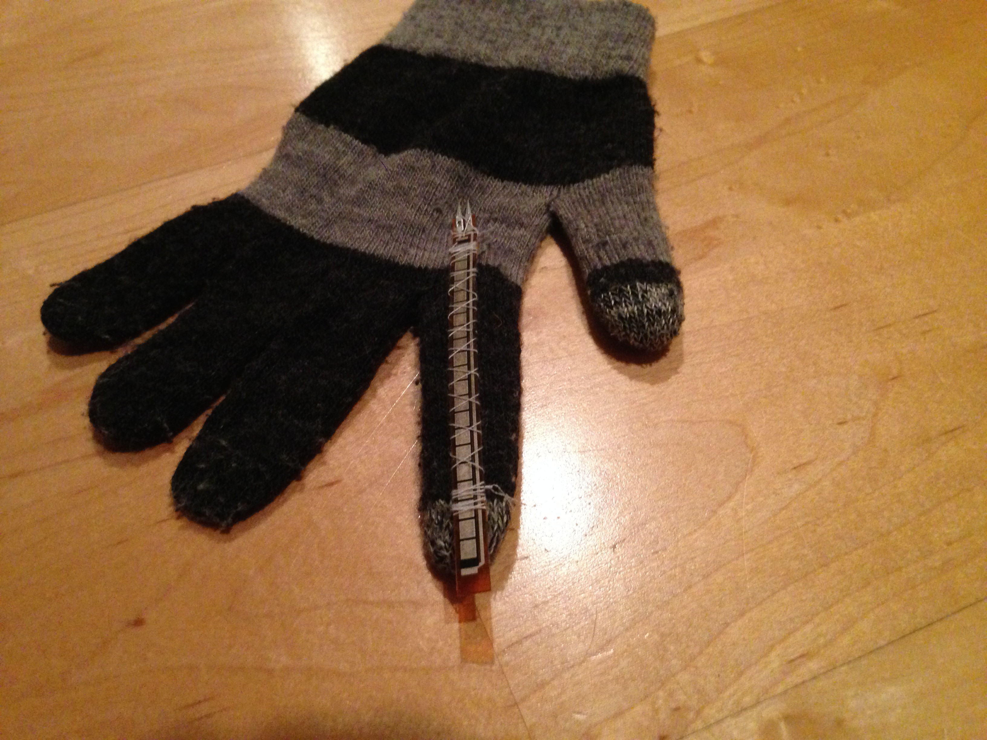


 ElectroBoy
 Nevyn
Nevyn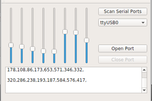
 ZaidPirwani
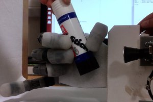
 Stephanie Stoll
your github links are not working sir. Can you provide me the code and schematics for transmitter and receiver??