 Hugh Darrow
 I've made this my personal phone so the progress should be steady and fast as any bugs, problems, or needed features I'll need to implement before I can use them, forcing me to do whats necessary is a pretty short amount of time.
My goal is to have a single, handheld, portable, fits in pocket lasts a few hours, open source top to bottom, cell phone. I will first develop all the software and hardware on shields, protoboards, and breadboards, and once I feel its sufficiently usable, and no other hardware modifications are necessary I'll make a single board with all the chips, display, and gizmos on one board. After which I'll use a 3D printer to print a small case around the necessary components. After that most likely do a crowdfunding campaign for anyone that wants to buy one.
Some future hardware and features are to have LTE modem, GPS(the sensor not the software), bluetooth(both audio and TX/RX), display-out(possibly DVI), audio music player(both MP3 and Vorbis), web browser, Ringtones, Accelerometer, watch mpeg files, and other cool features I can think of. That to me is great thing about open source, and being built by me and not some X company, that only cares about the money. I'm not in it for the money, I'm in it, because I have a vison of perfection, awesomeness, coolness, creativity, and overall, just one look at it, and think that's awesome. If you can think of any features that sound cool, and are reasonable, let me know, I'd love to hear them.
If anyone has questions don't hesitate to ask, I'm not pompous or an asshole like some people can be. I want this project to be able to be recreated by anyone with rudimentary electronics and software skills, and by the time I finish and you follow all the steps you'll understand everything that took place.
There has been multiple hardware changes since the beginning of the project logs, please be aware.
TheHackaDayPrize Submission Video and Concept
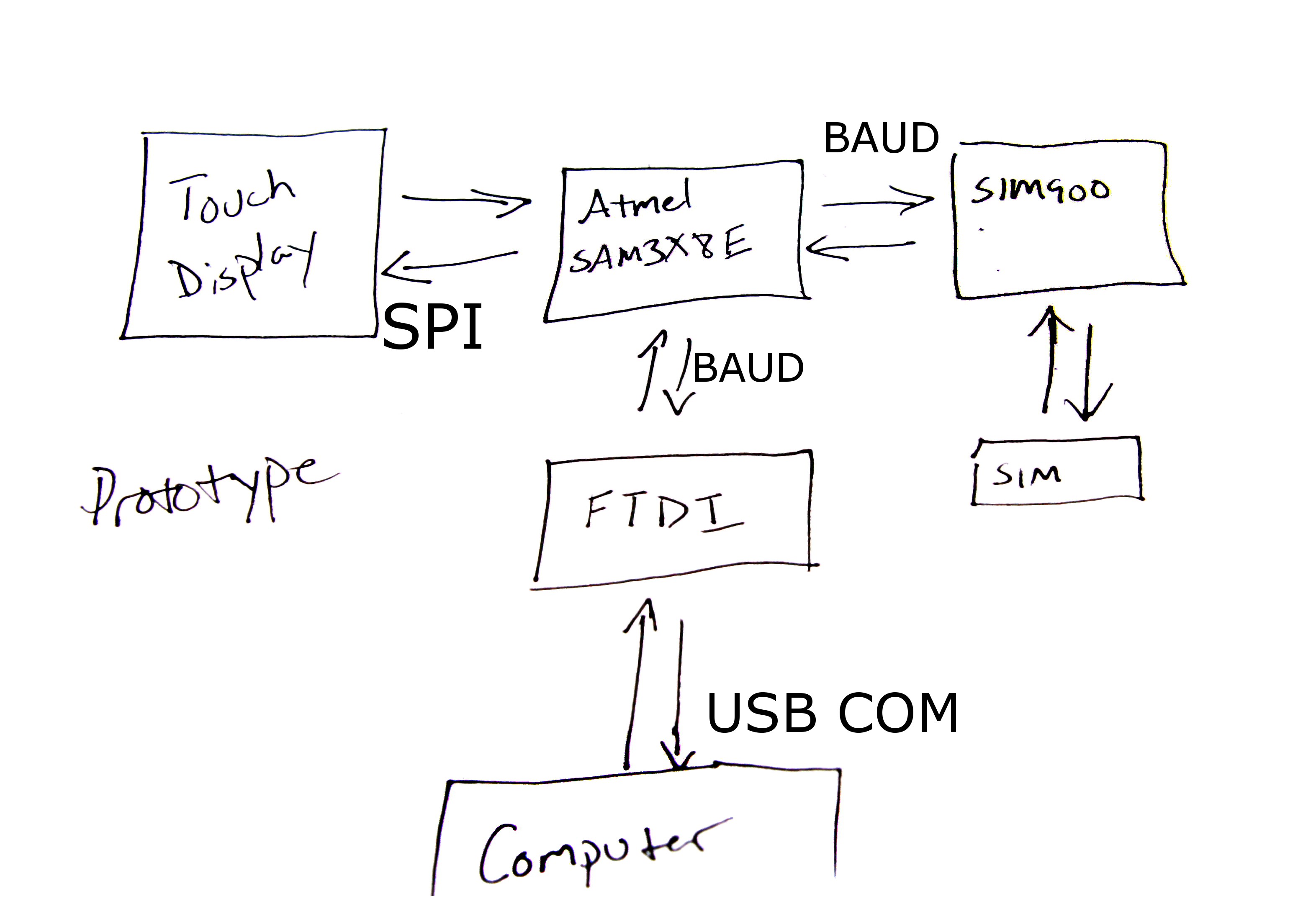
Block Diagram
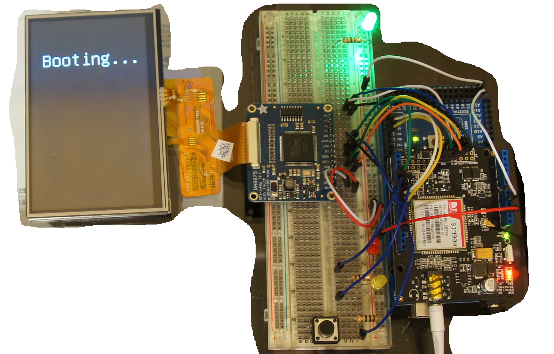
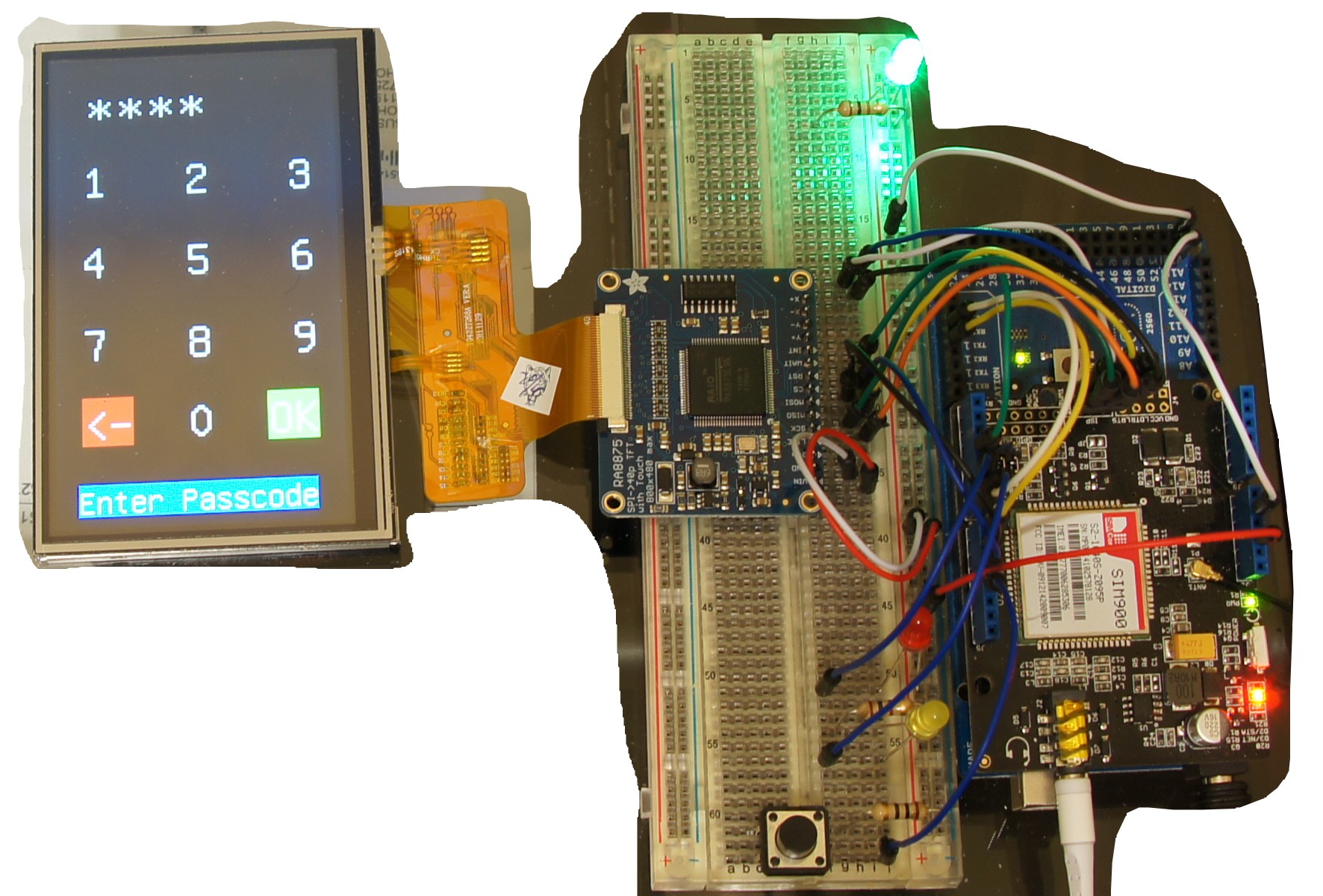
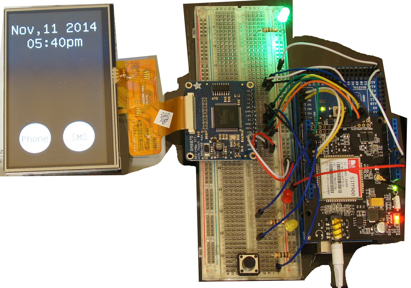
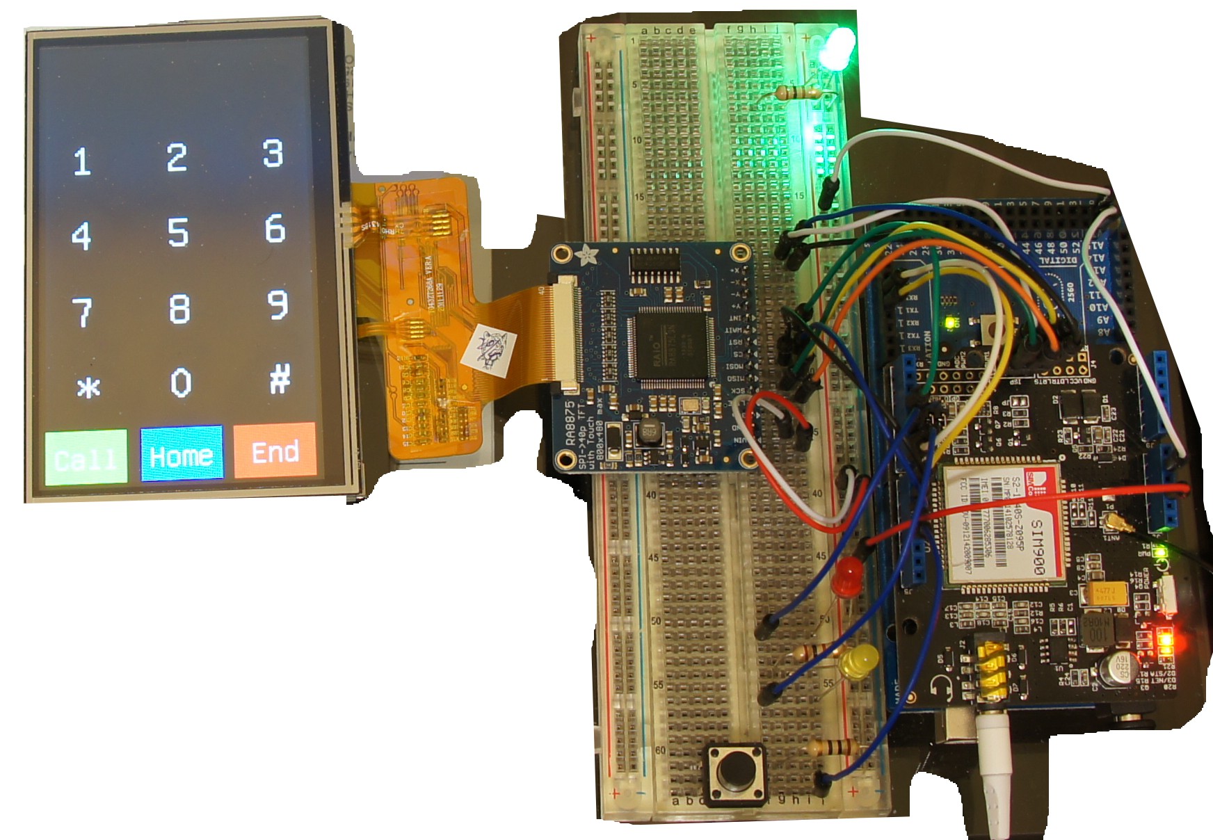
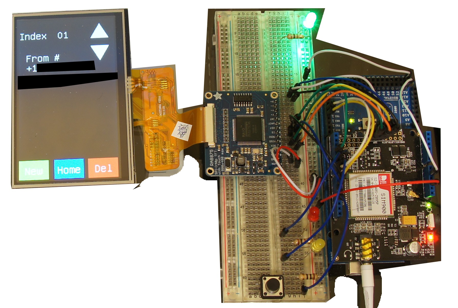
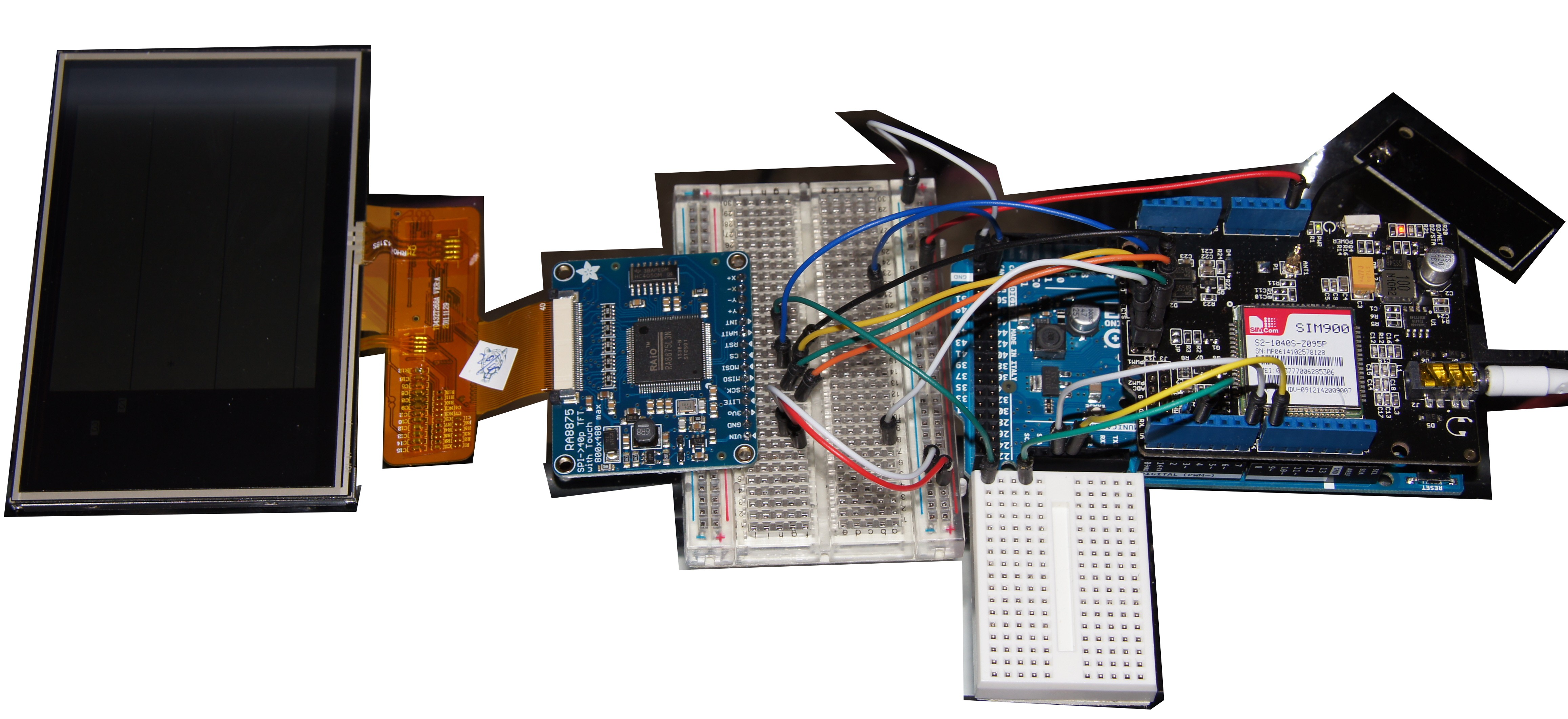
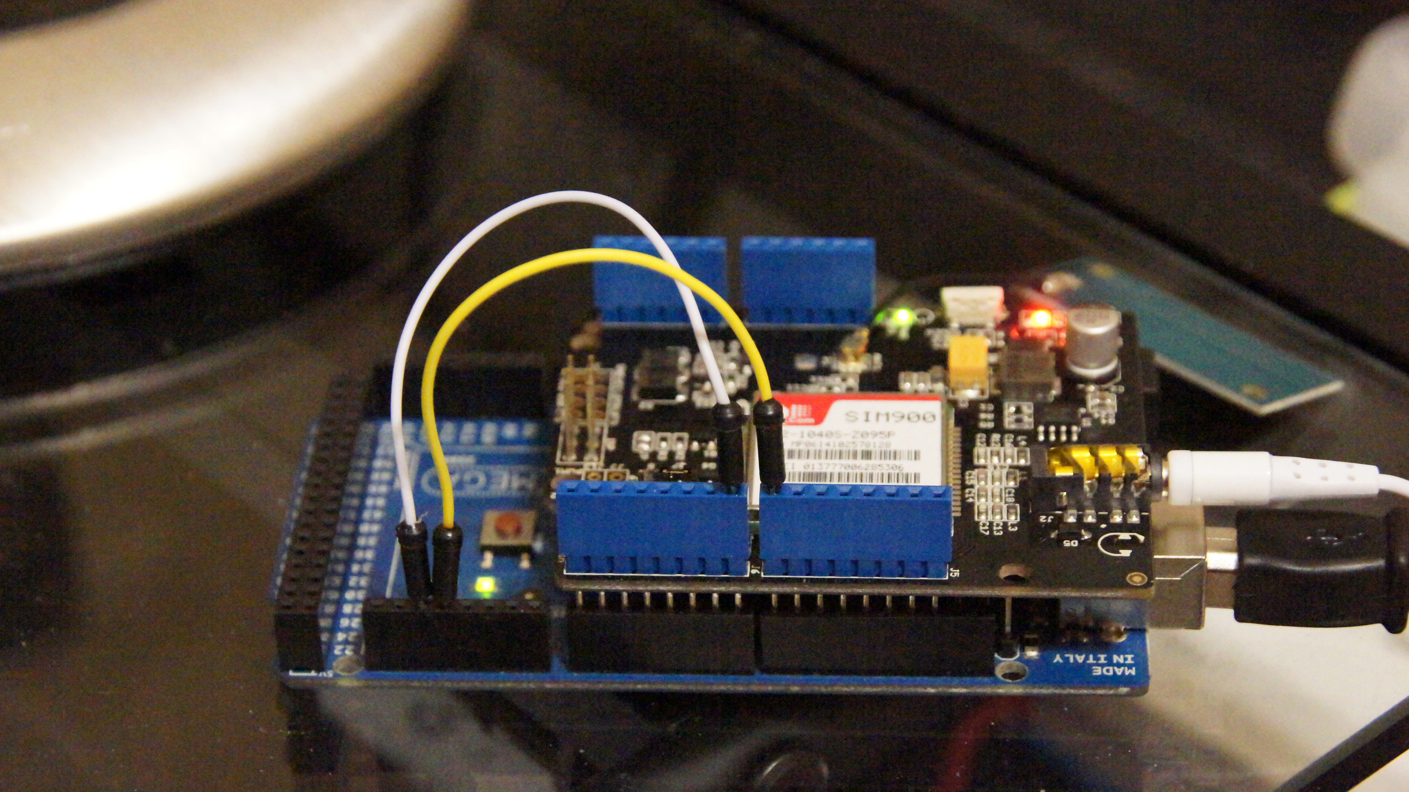
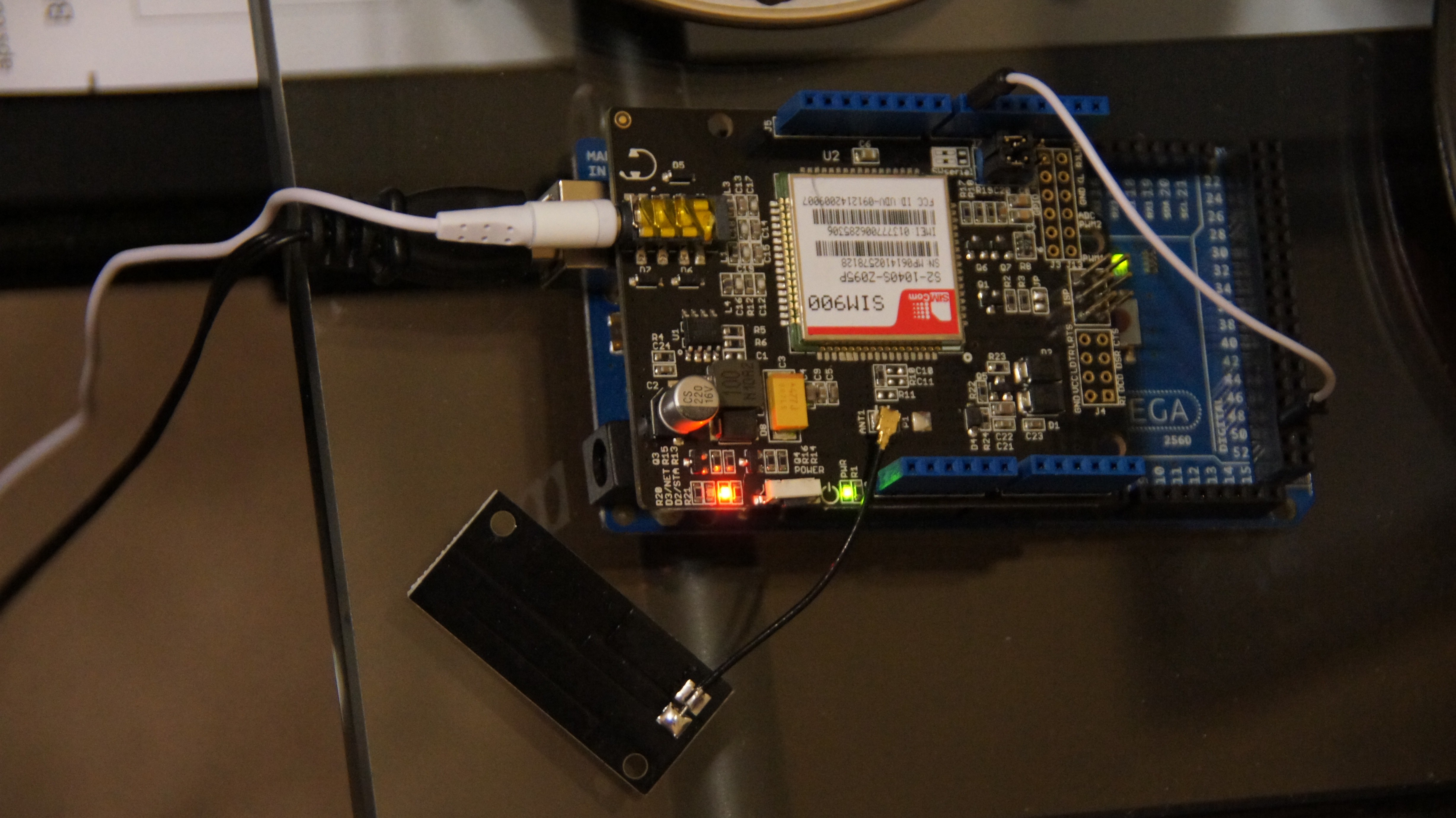
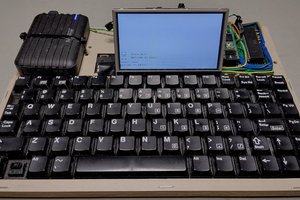
Prototype
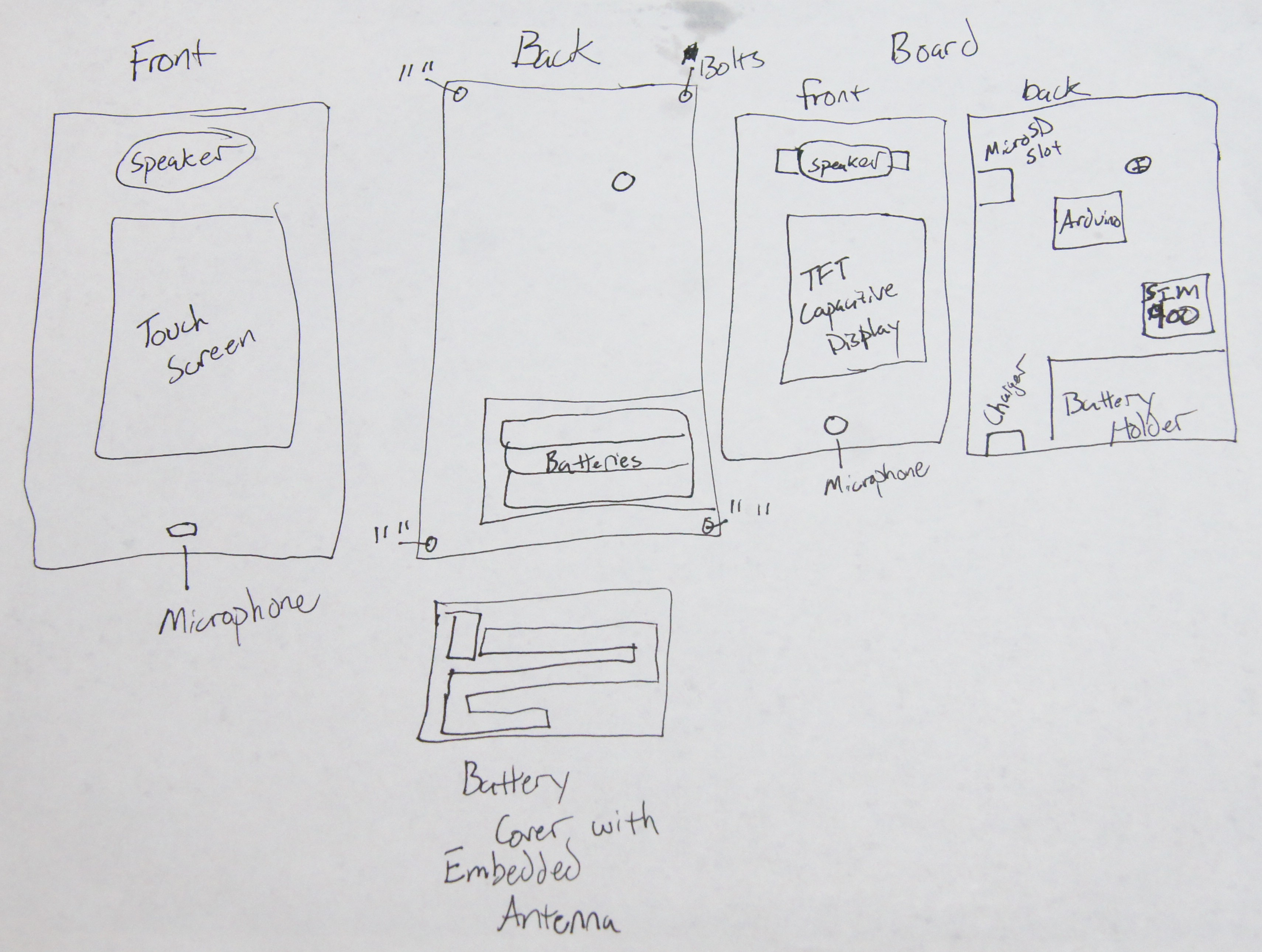
Concept Idea for finished project


 Albert Gonzalez
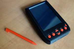
 brtnst
https://picasaweb.google.com/111890741167251011072/HomemadeGSMPhoneTest1
https://plus.google.com/photos/100113000254836852651/albums/5953521522952234769?banner=pwa&authkey=CMmltK_Wi6D-fw
https://hackaday.io/project/558-Rotary-dial-mobile-phone
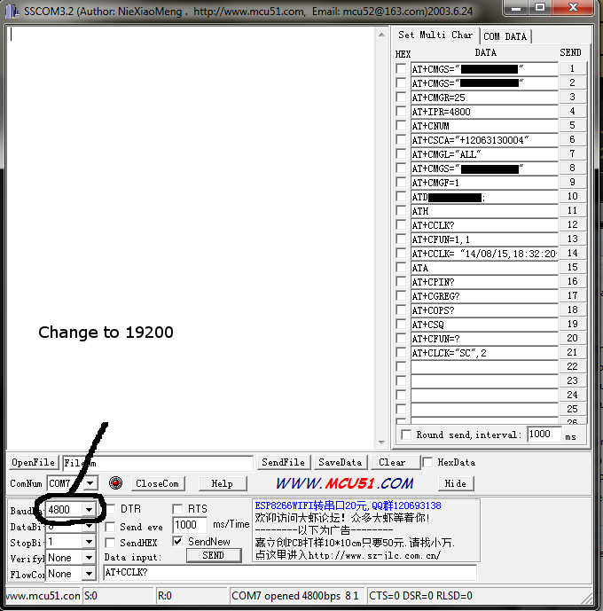
and I can tell you it is great fun. The absolutely most important thing with messing with SIM900 or similar is to make rock-stable AT command parser, with all the errors and messages checking. It is not that trivial task.