0%
0%
WIFI Interface Board
This board allows experimenting with a WIFI link on a general purpose MCU.
 Bharbour
Become a Hackaday.io member
Already have an account? Log in.
Just one more thing
To make the experience fit your profile, pick a username and tell us what interests you.
Pick an awesome username
hackaday.io/
Your profile's URL: hackaday.io/username. Max 25 alphanumeric characters.
Pick a few interests
Projects that share your interests
People that share your interests


 Hulk
Hulk
 Nicolò
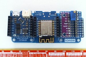
 Tom Meehan
Does anybody know of a book/website documenting current practice on implementing SMTP code? I have been going through the RFCs and they don't exactly paint a clear picture of how TLS plays with SMTP.