Close
0%
0%

Using old CD-drive as a music player

Trying to build a simple CD-player from an old CD-drive. I want it to read audio CDs, have button controls and an audio output.

Similar projects worth following
Using an old CD-drive as a "standalone" CD-player controlled by a microcontroller.

The point of this project is the learning process and documentation of it, not the CD-player itself.
There are many people saying that it's not worth building such thing, but I say it's bullshit. Re-using old electronic devices is best way to reduce e-waste and to learn about technology. Also your CDs become a little less useless :)

The goals for first version of this CD-drive reuse are:

  • read audio CDs
  • have control buttons (play, pause, stop, skip song etc.)
  • output audio signal

I would start with identifying key knowledges that one needs to make such project and gathering resources.
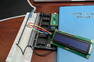
First build would (most likely) be controlled with an arduino and other necessary electronics. In future I'd like to learn how to shrink-ify project and only use components that are really necessary for the job.

I'm new in this community and begginer in electronics- constructive critiques, opinions and help are welcome!

Arduino to IDE v1.pdf

Schematics of the Arduino to IDE Interface adapter. Version 1. Made in EasyEDA.

Adobe Portable Document Format - 46.76 kB - 11/26/2017 at 15:12

Preview
Download

  • Dusting off the CD-drive

    jurc19201/19/2018 at 12:43 0 comments

    After a wild December full of socialising, dancing, heavy drinking and other joys of student life, it's time to switch back to the "geek mode" again. Having my "Arduino to IDE" interface built and (more or less) understanding how it works from the hardware point of view, it is time to dive into the software again.


    Where has the project stalled?

    As I mentioned before- what I am doing, has already been done by Carlos Durandal's ATAPIDUINO project. While I could simply upload his code (it works fine) and move on, I couldn't sleep without understanding how it works, what it does and why it works. Most of all I was wondering, how did he know what to do? 

    When I first tried to figure out how to communicate with CD-devices, I landed up in a mess of protocols, standards and various documents that had the right keywords, but I didn't understand shit there. What I did learn then was that ATAPI is the right thing to look for.

    Then, I tought I could answer my question by looking at CD-drive Linux drivers. But it turned out to be too complicated, for a newbie like me, to learn anything useful from it. The functionality (e.g. CDROMEJECT) in linux drivers matched the functions described in various ATAPI documents and ATAPIDUINO, though. So it wasnt a total shot in the dark.

    But this time, I am armed with a working interface, it's source code (atapiduino) and the right keywords in mind. I've decided to study ATAPIDUINO and compare it's working to the ATAPI standard. If everything matches, I've found the answer to my question- you can learn how to communicate with CD-drives, by reading the right standard.


    What standard to choose?

    There are some people that tried to simplify and explain the mess of ATAPI standards, CD-drives and various implementations. I found the table in the wikipedia article useful, since it summarizes the development of the standard and it's features.


    ATA development in a nutshell...
    ATA development in a nutshell...

    I have decided to study the ATA/ATAPI-4 standard, since it was the first to introduce the packet interface and the first to mention the CD-drives. I guess it contains all the fundamentals and doesn't include any special-fancy-features that were added later, which I don't need in this project. The standard is written by the T13 Technical Committee, which is a part of the NCITS, which is...whatever. Something that sounds like a big and scary round table of engineers, corporates and politicians trying to destroy the world, hah.

    Did you know?  The T13 Technical Commitee has a website with a list of all the standards, working drafts, documents etc. It looks precious. You can even choose between PDF, DOCX etc. The only problem is, you can't. It's just a text, not a download link! Even for working drafts. And by the way- why do you have to pay, to see a standard?!

    T13 Technical Committee webpage
    T13 Technical Committee webpage, where are standards are available...NOT


    Where to start reading?

    When you open the ATAPI standard, don't be like me and try reading it from the beginning- you will fall asleep immediately. Table of Contents is your friend :)
    I would say that the most interesting chapter to begin with is [ATAPI 5: Interface signal assignments and descriptions]. There you can read more about individual pin functions.


    ATA/ATAPI-4 standard excerpt
    ATA/ATAPI-4 standard excerpt

    I then discovered that there are two ways to communicate with an ATAPI device [ATAPI 6.1: Command delivery]. One way is...

    Read more »

  • Hello schematics

    jurc19211/26/2017 at 15:10 0 comments

    I always tought electronic schematics look cool. Finally I did my first - to make the messy sketch of my first circuit more clear. I couldn't decide between KiCad (as a FOSS fan it would be my first choice, but it looked a bit awkward judging from the reviews), EAGLE or Altium. I did it with EasyEDA in the end :)

    [Link to PDF version of the schematic]

    Arduino to IDE Interface schematic
    Arduino to IDE Interface schematic

    I was trying to think of readability, functionality and aesthethics. I would like to know some more principles of schematic design, are there any mistakes? What would be the "appropriate" way to do it? Is there something not really conventional? How would a professional draw it?

    Any easyEDA users out there? Should I use some other tools (like KiCad, Altium, Eagle..) instead? Why?

  • Building the interface v0.1

    jurc19211/21/2017 at 13:15 0 comments

    It's finally time to build this interface and move to the software part! After messing around with PCF8574 I/O expanders a little bit, I build the arduino -> IDE interface.
    I was mostly reffering to Carlos Durandall's ATAPIDUINO scheme, ommiting stuff I didn't understand or think was important.

    I tried to redraw and simplify Carlo's schematic, but ended up with even messier one and gave up. I'll do it properly in the next phase, to print PCBs (because this trough-hole stuff was a pain in the ass to do).

    My pathetic attempt to make the schematic prettier
    My pathetic attempt to make the schematic prettier

    I decided it's better to just write what goes where (included at the end of this log).

    After hooours of planning, wire stripping and soldering it was done. AND IT WORKS! :D
    I used an old ATX power supply to power the board and the CD-drive. I also used DIP IC socket adapters just in case I'd fry one of the I/O chips, and I used Arduino Nano.

    Controller board from an old CD-drive
    Controller board from an old CD-drive - wanted to get the IDE connector off

    Desoldering the IDE connector
    Desoldering the IDE connector - using soldering iron, solder suction pump and a flat screwdriver...

    Desoldered 40-pin IDE connector
    Desoldered 40-pin IDE connector - finally!
    Finished board, bottom
    Finished board, bottom (almost finished, messed up the red power supply wire at the molex connector)

    Finished set-up (without the IDE cable connected)
    Finished set-up (without the IDE cable connected)

    Listening to CD-player from the audio output in the front panel
    Playing the CD, listening from the audio output in the front panel, controlling the drive via serial terminal on a PC

    What goes where?

    ARDUINO:

    Arduino A5 (SCL)    --->    47kOhm resistor (pull-up)    --->    + 5V
    Arduino A5 (SCL)    --->    PCF8574 pin 14 (SCL)     (TO EACH PCF!)

    Arduino A4 (SDA)    --->    47kOhm resistor (pull-up)    --->    + 5V
    Arduino A4 (SDA)    --->    PCF8754 pin 15 (SDA)    (TO EACH PCF!)

    Arduino Vin    --->    + 12V
    Arduino GND    ---->    GND

    Each I/O expander has it's own address to distinguish between them, I'll call them PCF#1, PCF#2 and
    PCF#3 (addresses 0x20, 0x21 and 0x21 respectively).

    PCF#1:
    Address is 0x20

    pin 16 (VCC)    --->    +5 V
    pin 8 (GND)    --->    GND

    pin 1 (A0)    --->    GND
    pin 2 (A1)    --->    GND
    pin 3 (A2)    --->    GND

    pin 13 (INT)    --->    N.C. (not connected anywhere)

    pin 4 (P0)    --->    IDE pin 17 (D0 also DD0 or Data0)
    pin 5 (P1)    --->    IDE pin 15 (DD1)
    pin 6 (P2)    --->    IDE pin 13 (DD2)
    pin 7 (P3)    --->    IDE pin 11 (DD3)
    pin 9 (P4)    --->    IDE pin 9 (DD4)
    pin 10 (P5)    --->    IDE pin 7 (DD5)
    pin 11 (P6)    --->    IDE pin 5 (DD6)
    pin 12 (P7)    --->    IDE pin 3 (DD7)

    PCF#2:
    Address is 0x21

    pin 16 (VCC)    --->    +5 V
    pin 8 (GND)    --->    GND

    pin 1 (A0)    --->    GND
    pin 2 (A1)    --->    GND
    pin 3 (A2)    --->    GND

    pin 13 (INT)    --->    N.C. (not connected anywhere)

    pin 4 (P0)    --->    IDE pin 4 (DD8)
    pin 5 (P1)    --->    IDE pin 6 (DD9)
    pin 6 (P2)    --->    IDE pin 8 (DD10)
    pin 7 (P3)    --->    IDE pin 10 (DD11)
    pin 9 (P4)    --->    IDE pin 12 (DD12)
    pin 10 (P5)    --->    IDE pin 14 (DD13)
    pin 11 (P6)    --->    IDE pin 16 (DD14)
    pin 12 (P7)   ...

    Read more »

  • First productive steps

    jurc19211/21/2017 at 12:00 0 comments

    I figured out that my theory-based approach (with lots of spec reading and basic tutorials) won't get the CD-player going. And people have been trough all this before me, so why reinvent the weel.

    There was a bookmark in my browser, that contains most of the answers to my previous questions - ATAPIDUINO (by Carlos Durandal). How could I forget about this! I wanted to know and understand things, before moving to this already-finished arduino project. But how could that be better than studying an already working example *facepalm*!

    Serial to Parallel conversion magic box


    How do I connect Arduino to a 40-pin IDE connector? Connecting every arduino pin directly to IDE pin wouldn't work, I should rather do somekind of serial - parallel conversion (introduction to the topic). And that exactly what Atapiduino does, using I/O expanders for I2C bus (PCF8574).

    The PCF8574 I/O expander basically recieves bits one-by-one and when it collects a byte (8 bits) it "spits them out" simultaneously, each bit on it's own pin (rough description, probably not technically correct/exact).
    We send commands from a microcontroller (Arduino) to PCF8574 I/O expanders using I2C protocol (lots of good tutorials about I2C on yt and google). 

    I first tried connecting an I/O expander to an arduino and a LED, to learn how to work with theese.

    PCF8574 I/O expander connections

    Breadboard test

    Only thing you have to set before toggling pins on/off is the address of the device- datasheet (chapter 7 my case) describes this well. And the I2C serial communication things like start & stop bits, parity, baud rate etc. - you don't have to worry about theese, if you use arduino. The Wire.h library handles all this, so all you have to do is begin communication, set the address of the slave device (the I/O expander is slave, arduino is master) and start sending bytes.

    #include <Wire.h>
    
    void setup() {
    
      // Start I2C interface
      Wire.begin();
    
      // Set parameters for communication with our PCF8574 I/O expander.
      // We've set all the address pins (A0, A1, A2) low,
      // so our I/O address is 0x20h according to the datasheet.
      Wire.beginTransmission(0x20);
    
      // Byte we want to send. Bits are mapped to pins P0 -> P7
      // (each pin represents one bit of a byte). 
      // E.g. 0x07 (0b00000111) sets pins P0, P1, P2 HIGH and others LOW.
      Wire.write(0x07);
    
      // Transmit / send the byte
      Wire.endTransmission();
    
    }
    
    void loop() {
    }

    You can test if your circuit works, by measuring voltage on the P0->P7 pins of the I/O expander (one voltmeter probe to GND and another to one of the P0->P7 pins). For our example P0, P1 and P2 should be HIGH (5V), others LOW (0V).

    I was struggling with my I/O chip for hours, only to realize that it didn't work. So be aware that ebay stuff sometimes doesn't work (lesson learned the hard way). Yay :)


    Any electrical engineer wants to comment the use of PCF8574 in this application? If you had to connect a microcontroller to a 40-pin IDE device, what would you use? What would be the simplest component to use in this application? What would they teach you in school? Which chip would they use in industry?

  • Digging deep inside Linux drivers

    jurc19209/10/2017 at 21:46 0 comments

    My theory is: if my computer is communicating to the CD drive, so can I. And thanks to the free & open source community, I can see how "he" does it.

    I guess reading about some kind of Linux CD drivers would be a good start. I refreshed my C programming language knowledge, by writing some simple programs and started reading about Linux kernel and drivers. It was a huge and interesting "detour", but had nothing to do with this project. Crap!

    One of the simplest task I could think of was to eject the cd tray. Thanks to this awesome Introduction to the Linux CDROM Interface it was done in no time.

    /* eject.c
    ** Copyright Paul Dwerryhouse, 1997-2004
    */
    #include <sys/types.h>
    #include <sys/ioctl.h>
    #include <fcntl.h>
    #include <linux/cdrom.h>
    #define CDDEVICE "/dev/cdrom"           /* CDROM device */
    int main(int argc,char **argv)
    {
       int cdrom;                           /* CDROM device file descriptor */
       /* Open the CDROM device. The linux/cdrom.h header file specifies that
       ** it must be given the O_NONBLOCK flag when opening. My tests showed
       ** that if this isn't done, this program will not work. 
       */
       if ((cdrom = open(CDDEVICE,O_RDONLY | O_NONBLOCK)) < 0) {
            perror("open");
            exit(1);
       }
       /* Use ioctl to send the CDROMEJECT command to the device
       */
       if (ioctl(cdrom,CDROMEJECT,0)<0) {
            perror("ioctl");
            exit(1);
       }
       close(cdrom);
    }

    The main things here are ioctl and the cdrom header file.

    IOCTL (Input Output ConTroL) is "a kind of device-specific system call". Every device has it's own ioctl commands. Longer explanation is in "The Linux Kernel Module Programming Guide".

    And the cdrom header file can be found in /usr/include/linux/cdrom.h . It contains commands and definitions for accessing CD-drive. I got mine from Linus Torvald's github - linux kernel source tree. Actually there are two cdrom.h files in the kernel source. The one I found (more) useful is in /include/uapi/linux/cdrom.h and the other one is in /include/linux/cdrom.h . Confusing at first, but here's the answer why.

    My friend Otto joined me, and we tried sending various ioctl commands. Sending CDROMSTART and CDROMSTOP commands was succesfull, but we couldn't tell what they are doing. Commands CDROM-PAUSE or -PLAYMSF for example didn't work on our device -> ioctl: operation not supported.

    Command CDROMSUBCHNL (read sub-channel data) was interesting, since it outputs "current" track, minute, second and frame (1sec = 75 frames).
    After playing a song from cd and stopping (and exiting the audio program) the same command gave different results. Exactly where we stopped the playback.

    Next challenge was to read audio from the CD. We're guessing that -PLAYTRKIND (Play track / index addressing) and -PLAYMSF (Play track / minute-second-frame addresing) refer to playing audio from those analog audio outputs on the CD-drives themselves. Because those operations were not supported on our modern CD-drive without analog audio output.

    Anyway, we got to read the audio with -READAUDIO command!
    We put  the returned output to a file (.wav) and played that with aplay cmd audio player. Btw the flag -f cd gives you the correct output, but playnig around with different bitrate and channel number might produce funny results.

    After playing around we tried to go one level deeper into the kernel. I really wanted to get to the switch statement that would recieve those CDROM-xy commands we send via ioctl function. Well, it wasn't easy to find it but it is in [kernel source]/drivers/cdrom/cdrom.c at line 3331. We followed function calls a bit more, but soon we got lost in all the files and stopped at this point.

    switch (cmd) {
        case CDROMMULTISESSION:
            return cdrom_ioctl_multisession(cdi, argp);
        case CDROMEJECT:
            return cdrom_ioctl_eject(cdi);
        case CDROMCLOSETRAY:
            return cdrom_ioctl_closetray(cdi);
        case CDROMEJECT_SW:
            return cdrom_ioctl_eject_sw(cdi, arg);
    // And so on...

    I guess finding information about the cd-drive controls from linux drivers was not a very productive idea. But it was fun and we learned a lot, studying...

    Read more »

  • What language does it speak?

    jurc19208/21/2017 at 22:23 0 comments

    Diving into the wikipedia page, I learned that I can forget the name "IDE" (Integrated Drive Electronics) and think about "ATA" (AT - Attachment, from IBM's computer called AT).

    There are different versions of ATA standard, each adding/changing some features and having it's own name. For this project we will need to read about "ATAPI" (AT Packet Interface). I tried to find some more tangible information on how to program it, starting with those wikipedia references. After scrolling briefely trough pages of ATA standard evolution, I came across a page named: "Making Sense of IDE/ATA Standards and Compatibility". Well...even that didn't help that much :(

    After drowning in all this protocols and things, I decided I'll try something else. My computer has a cd-drive, and I have linux OS. This means that I can read the source code. So in theory (!!!) I could find out which commands my computer sends to the CD drive. I know, I know, there might be a faster or more direct way of getting to this info, but since I like messing with linux, drivers and low level stuff in general- why not? :)

  • A dive into the CD - drive

    jurc19208/21/2017 at 19:38 0 comments

    I started with exploring my CD - drive. How does it work, how do I control it and what does it output?

    The "how does it work" part you can find easily, if you know how to open google and search for it. I won't go into this here.


    Next step for me was reading all there is to read on the housing of my CD-drive. I was happy to see that the model I have, is so well labeled- all the connectors on the back are labeled with words. I don't see such effort in newer devices so often.


    1. POWER SUPPLY


    Powering the drive is quite straight-forward (thanks to all the labels and stickers). In my case it says: "POWER SUPPLY DC 5V 1.5A / 12V 1.5A" .

    Now, for the connector (labelled "DC INPUT") couldn't find a better answer than: MOLEX. As you might see "Molex" isn't one specific model of connector, but tons of them- crap! According to their webpage, the keyword that takes you one step closer to your CD- (and hard-, and floppy-) drive is "8981-series". That's good enough for me, for now. You can scavenge some of them from your old computer's (ATX) power supply!

    Thing about the power supply that bothered me was: do I need both 12V and 5V supplies? Shouldn't only one be enough? After some reading on forums, I found out that you DO need both. One for the motors and "heavy weight stuff", other for the control circuit, chips and stuff. Having two separate power supplies looks a bit gipsy-ish solution, so I will try to find more elegant solution later. Any Electrical Engineers with an advice here? :)

    2. AUDIO CONNECTOR

    I noticed that there already is an audio output connector (link). And some of my CD - drives even have two of them, digital and analog one. This means I could hook an amplifier directly to the drive, without having to deal with digital to analog conversion (the part which I'm "afraid" the most - have the least knowledge) -yay! :D

    3. SLAVES AND MASTERS CONNECTOR

    There is a connector that enables you to switch the CD drive between submissive-mode and master-dominating-your-life-mode...or something?
    It's actually a connector for setting "Master" or "Slave" mode of the device (computers IDE controller needs to know this). Afaik it's there for historical reasons and since I only have one device, "Master" mode should work fine.

    4. IDE INTERFACE

    Now the big connector...and the big knowledge gap for me. The IDE interface connector. You know you're entering the messy world of standards and protocols when googling "IDE interface" first takes you to "Parallel ATA" wiki. What? And it is a loooong page, full of history.

    Before diving into it: IDE interface connector is used for connecting the drive with the computer's motherboard. It's an interface, for sure. And at the moment I only know that sending the right signals to the right pins (from Arduino, for example), will control my CD-drive. Yay! Also, IDE controller is an interesting keyword.

    But what "language" does it speak? What bits do I need to send to which pins to open the cd-tray for example, or to skip a song? I guess I'll have to find info about some protocols...

  • Hello World!

    jurc19206/02/2017 at 11:41 0 comments

    I got this idea of transforming an old CD-drive to a music player when I was tearing apart an old computer. So much fun! But will I ever actually use any of theese salvaged components? After they gathered dust for few months it was time to either trow everything away or start making things out of them. I think this youtube video was first time I saw this kind of CD-player.

    I know that my device has to:

    • communicate with the CD-drive (to send commands such as play, stop, next ect. and to read data from CDs)
    • control user interface (physical buttons, maybe also a display)
    • convert digital data to audio signal

    Bird's-eye view diagram


    The diagram above shows general parts that I need to study and connect in order to get my old CD's playing. (One of the first (original) CD's I ever got, was  "Soundtrack to your Escape" by In Flames. I got it for santa when I was about 11, hah :)

View all 8 project logs

Enjoy this project?

Share

Discussions

CD32Freak wrote 01/16/2024 at 15:44 point

In case anyone is interested, the book Bharbour mentioned ( "The SCSI Bus and IDE Interface, Protocols, Applications and Programming" by Friedhelm Schmidt) is available at the Internet Archive:
https://archive.org/details/The_SCSI_Bus_and_IDE_Interface_2nd_Ed/page/n5/mode/2up?q=Friedhelm+Schmidt+SCSI

  Are you sure? yes | no

ddscentral wrote 05/18/2020 at 19:13 point

Nice project, but that CD drive already had play/skip buttons on the front. All it needed to be a CD player was a power supply. It's somewhat of a waste to use such drive with an Arduino. A drive without integrated control buttons would have suited better.

BTW, you don't really need a PC PSU, any source capable of providing 12V and 5V will work (for example a 12V PSU/power bank with a simple 5V DC-DC converter). Also, power ratings on most drivers are inflated. You don't really need 12V 2A to play CDs.

  Are you sure? yes | no

The Curious Lorenz wrote 01/18/2020 at 19:59 point

Hi jurc192,

nice work :-)

I also couldn't help myself to add my 2 cents to the ATAPIDUINO project!
As a challenge I was able to successfully control a CD-ROM drive by using a single atmega328 chip, where every single I/O has been used (yep, including RESET and AREF!) The atmega328 is also controlling a display as well. The only external component is a NPN transistor and a limiting resistor which are amplifying the tiny control signal which can be sourced from AREF. Clearly, no crystal is used but the internal 8MHz clock source.

Unfortunately I haven't yet got the chance to go on with the project for which I would like to get rid of the actual bulky DVD-player case, pick and use a different and smaller case, get a simple HD44780 display or similar and rework the logic to not be blocking.

Additionally, I would like also to find out a way of using more recent and silent DVD players for which the original author and me were unable to make them work with ATAPIDUINO.

I'll leave also some more background history: I have attempted to use a 8255 as a I/O interface but unfortunately a huge quirk lives in that chip, namely the fact that switching I/O direction to output causes the output to get low nevertheless for a brief moment, causing a brief pulse on the CS lines therefore causing the communication to go crazy (they are active-low), IIRC.

PS: https://github.com/lmiori92/AtapiduinoSingleChip -> the github repo is really messy as the original work was (pardon, Mr. Original Author)

Cheers & Happy Hacking!

  Are you sure? yes | no

geiss.kh wrote 10/08/2019 at 07:34 point

Wow ... very nice project  ... did you make tests with harddiscs too ....  that's my interest  ....

  Are you sure? yes | no

Bharbour wrote 09/10/2017 at 22:36 point

Try looking at the SCSI spec. ATA commands are pretty much just SCSI wrapped into a different interface. The SCSI documentation is pretty good. I am looking at a book called "The SCSI Bus and IDE Interface, Protocols, Applications and Programming" by Friedhelm Schmidt. ISBN 0-201-42284-0 and it has a chapter with CDROM commands in it, including the Play Audio and Play Audio MSF commands that you mentioned. Copies of the SCSI spec are available for free on the net in various places. You probably want at least SCSI  2, since they did a lot of changes between 1 and 2.

ATA is a 16 bit parallel interface, so it will be easiest to drive the ATA port with a 16 bit port.

Good Luck,

BobH

  Are you sure? yes | no

jurc192 wrote 09/11/2017 at 10:23 point

Aha okay, that's great information! I'll check it out and will let you know how it went :) thanks

  Are you sure? yes | no

Similar Projects

Does this project spark your interest?

Become a member to follow this project and never miss any updates