 Matias N.
While it may not seem so, from last log entry I made significant advances on this new revision of the project. Thus, I wanted to tell a bit of the project status.
You may also noticed I renamed the project to BicycleCompanion (dropped the MINI suffix) since I feel this is still the original project but with one more refinement step. I also renamed the (never finished) teensy-based project so that no confusion is generated.
It is also interesting that from all my (four) projects on Hackaday, this one received a constant influx of about 100 views per week. While it may be the result of google crawling the site I choose to think that there's at least some interested people. So, I hope to provide more project updates soon to show my progress.
Prototyping
While it may not be the typical choice, I'm particularly inclined towards writing the firmware for my electronics projects using the NuttX real-time operating system. In contrast to other RTOS, NuttX feels like a "tiny Linux" in that it is POSIX compatible and aims for high-level hardware abstractions. This is very good to decouple the logic from the specific hardware and maximize re-usability. However, it also comes at the cost of a steeper learning curve and friction than simple hacking something using Arduino.
As an initial development platform for BicycleCompanion, I chose to work on the ST Nucleo L476RG board, which has very good support on NuttX and also provides a very nice set of features. However, there are always some little (and not so little) things to improve in NuttX once one starts to poke around various parts of the OS.

Besides some small required changes (like adding support for low-power hardware timers or LPTIM) I found that the power-management algorithm baked into NuttX was a bit high-level and did not let one to have tight control over entering and exiting low-power run modes. For this reason, during the last few weeks I reworked NuttX PM system to allow for different PM algorithms. In particular, I added a separate "greedy" algorithm that always tries to go as soon as possible into a low-power run mode (unless an application or driver requests it to stay at a specific level). This is working really well and I have already handled STOP mode on the STM32L4 succesfully.
A second important step was to tame the Sharp Memory LCD. While a driver was already present in NuttX it didn't quite fit in a low-power setting. Specifically, the Sharp Memory LCD requires a pulse between 1-60Hz to be sent all time to maintain the currently displayed data visible and at the same time avoid burn-in. The NuttX driver used a simply pin toggling mechanism tied to a timer interrupt. Thus, taking advantage of one of the LPTIM timers, I added support for PWM generation using this peripheral, which allows me to send the required pulse, even while the MCU is in deep sleep. This is also working perfectly.
In regards to the display, I also added support for the latest littlevgl library in NuttX (it officially supports an older version) and developed a simpler driver to access the LCD from littlevgl. So far I have managed to start designing a very simple system of different screens (time, speed, etc.) and a boring splash screen.
My next and final step before going into building a BicycleCompanion prototype is to test the other LPTIM in pulse-counting mode, to sense the bicycle wheel turning. I originally considered (as in the previous BicycleCompanion design) a latching hall sensor to receive pulses whenever the magnet of the wheel passed over it. However, after looking at various models, all Hall sensors tend to be a bit power hungry (a few mA when measuring). After much consideration I decided to go the easy and zero-power way: use a plain reed switch. This also has the advantage that I do not need to fabricate all the sensor mounting and so on, since there are hundreds of cheap bicycle computers and can try this on.
Circuit Design
I have more or less finalized the schematic for BicycleCompanion. I added everything I could think I would need but I could probably add other (experimental) components. For example, I'm unsure if I should add some front light system for the LCD or not. I'm not sure if it would look good enough to justify its use. Anyway, I have many free pins so if you have a recommendation for something else to add, please let me know! (but please have in mind that I'm looking into supply currents measured in uA).
At the moment this is how much of the MCU is under used. As I said, many free pins (and peripherals) still available. The USART will probably be exposed to pins for easy access to NuttX console.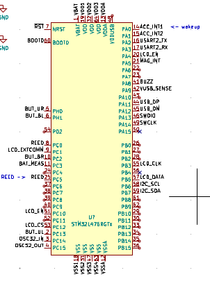
 In the following you can see the four buttons, LCD, SWD and USB connector. I will probably modify the SWD connector to also expose the USART.
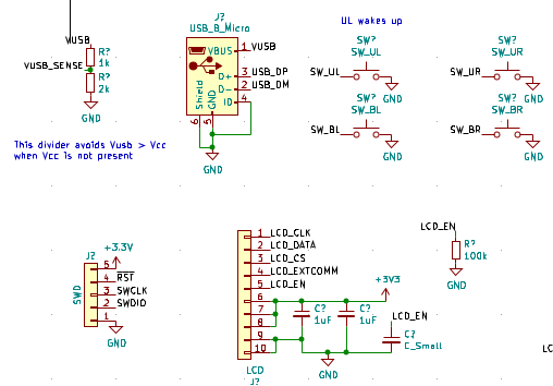
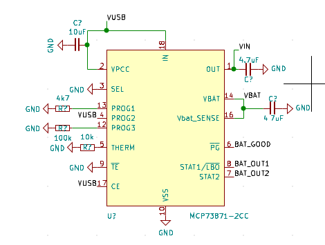
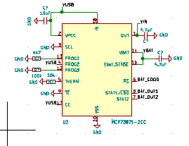
This is the charging IC which feeds from USB and charges the LiPo. It supposeddly handles powering the rest of the system simultaneously (assuming USB port gives enough current) without affecting the battery itself due to the parasitic load:
This little (but so important) part of the circuit allows me to measure the battery without actually consuming a considerable amount of power in the process:
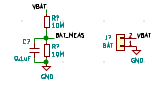 You could use only a resistor divider with high enough resistance, but you will have trouble charging the internal ADC capacitor. So, by adding an extra capacitor "outside" you suposedly avoid that problem. There may be better circuits but I did not want to over complicate this.
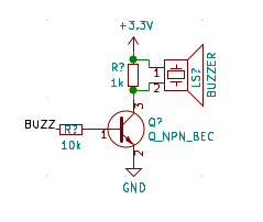
This is the piezo buzzer. Again, there are more efficient configurations but require much more components and would like to keep things simple. In this case it will simply not produce a sound as loud as it could be but I think it should be good enough:
 The following is the Franklin sensor which I believe is the most complex part of the design. However, it is a copy of an existing circuit so it should work OK:
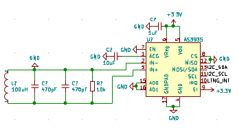 I will have to consider the placement of the antenna so that I do not pick up much noise or block its reception.
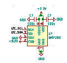
Finally, these are the BMP280 and LSM303 sensors. Again, just mostly copied from the datasheets:
I will publish another log once I get the schematic finalized and have a reasonable PCB design. Pretty pictures to come =)
Again, please let me know about any thoughts or comments about the project or the circuit in progress.
Discussions
Become a Hackaday.io Member
Create an account to leave a comment. Already have an account? Log In.