The basic:
At first I would like you to understand, what is the main parts of a VFD.
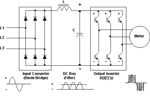
On the picture you can see a variable frequency drive power section diagram, with the main parts.
- The first is the bridge rectifier diodes. You see 4 diodes if your device is require one phase, or 6 diodes if it require 3 phase input.
- In the middle you see an inductor and a condensator for smoothing both the voltage and the current. It is called "DC - bus"
- On the right side of the picture, you can see the 3 phase IGBT bridge. The bridge contains 6 high power IGBTs.
Start the repair
At first you shoud not want to power up the drive, without you actualy measured the power section! If you power up the inverter without you measured it and it has a short on the power section you may get a big suprise, so be careful.
From experience, I can define three most common fault, that VFDs have:
- The most common problem comes from some people miss reading the sticker on the drive, what voltage is it require. With this move, they often kill the diode bridge and some input protection VDR (Varistor).
- The second common problem is the condensators, what are the weakest component in the entire drive. The condensators life time is much shorter then any other parts in the drive, so if you repair any damaged VFD you shoud replace those as well.
- The third problem is often come with the bad heat dissipation. If the IGBTs or the diodes get too hot, one, two, or even more go to short. This caused by the IGBT drive circuit fault, or the heat shock on the power section.
On this, I would like to show, how I repaired a Danfoss FC302 drive, which was faulty.
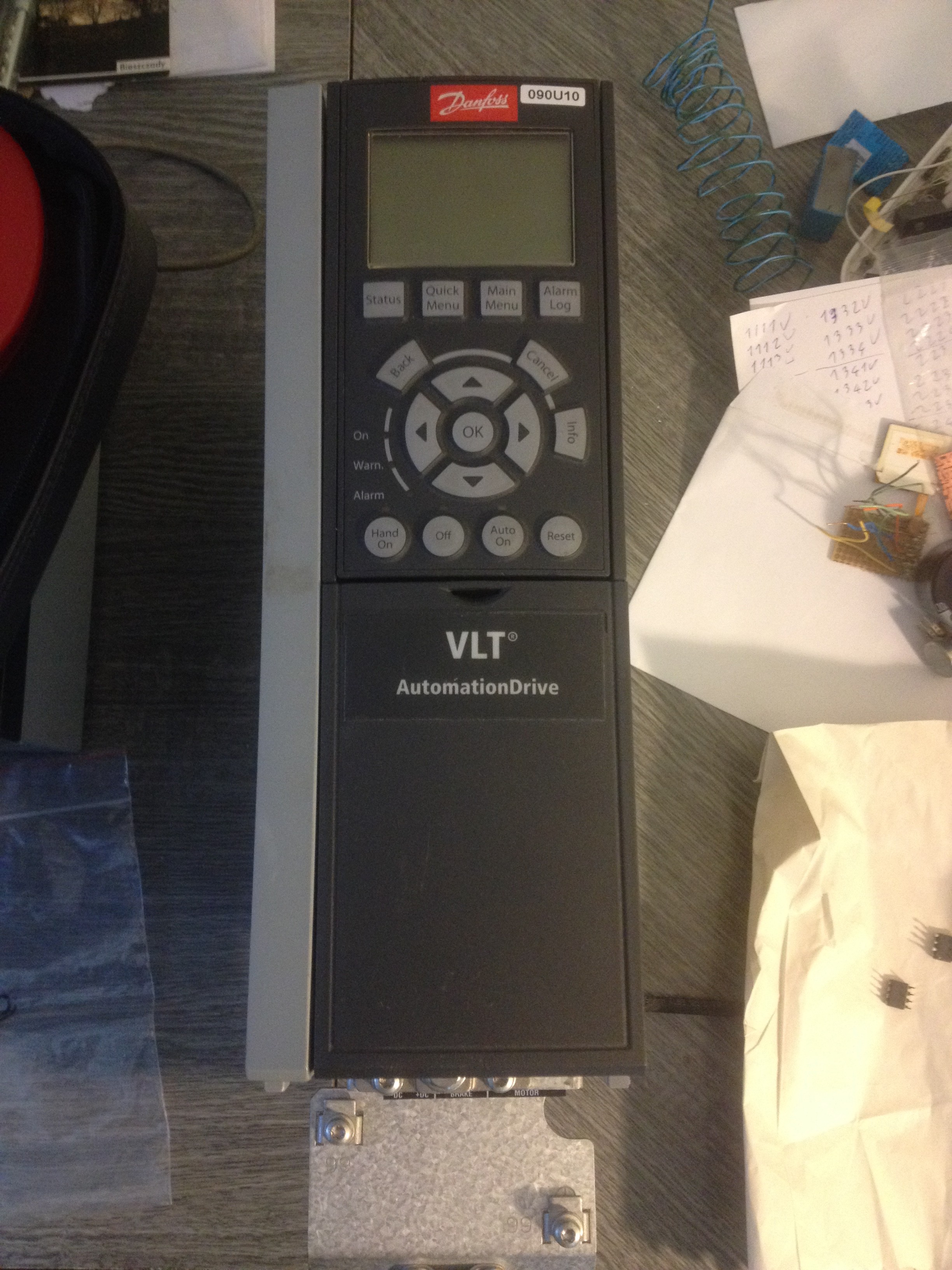
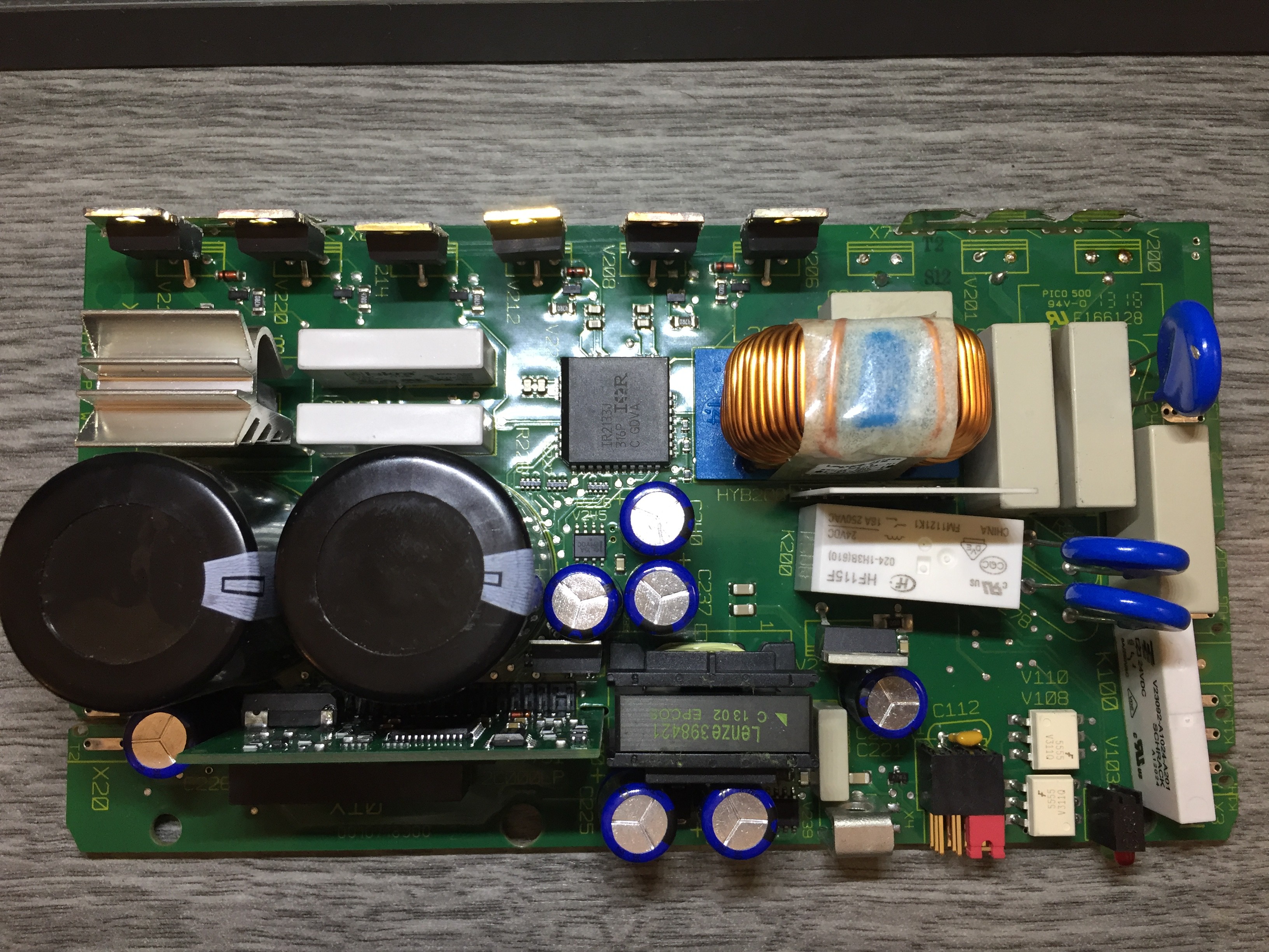
At the start it looked like this. This is a 2.2KW output power rated inverter, with 400V three phase input.
I knew it had a bad power section in it, but I would like to measure it. For the measurment you has to have a multimeter, with diode check function. At first I need the 3 phase input and the DC - bus lines for check, if the rectifier diodes are not shorted.
You can measure this, if you place one probe on the negative DC line first and then with the other probe you probe to the tree phase terminal. After the same with the positive DC line and the three phase terminal. If you did it right you shoud see the readings between 0,3V to 0,5V. If you see 0, you find a shorted diode, if nothing changed on the meter, you shoud reverse the probes or, that diode is also dead.
Often all diode good, but the IGBTs are bad, so now you have to check the IGBTs as well, before you can turn on the device.
The IGBTs have inside an antiparallel diode, so it helps with the measurments as well. Basically you can not check an IGBT inside the circuit, but what you can check is the antiparallel diode and it tells you a lot. Usually if the IGBT go bad, it go with the diode as well, so if you can not measure the diode, or you measure short, you get a bad IGBT as well.
You can measure the IGBTs with the same method then you measure the diode bridge on the input, so you put on a probe on the dc bus, with the other you check the output terminal on your drive.
Lets see an example how it is lookes like when your power modul get a short in it.
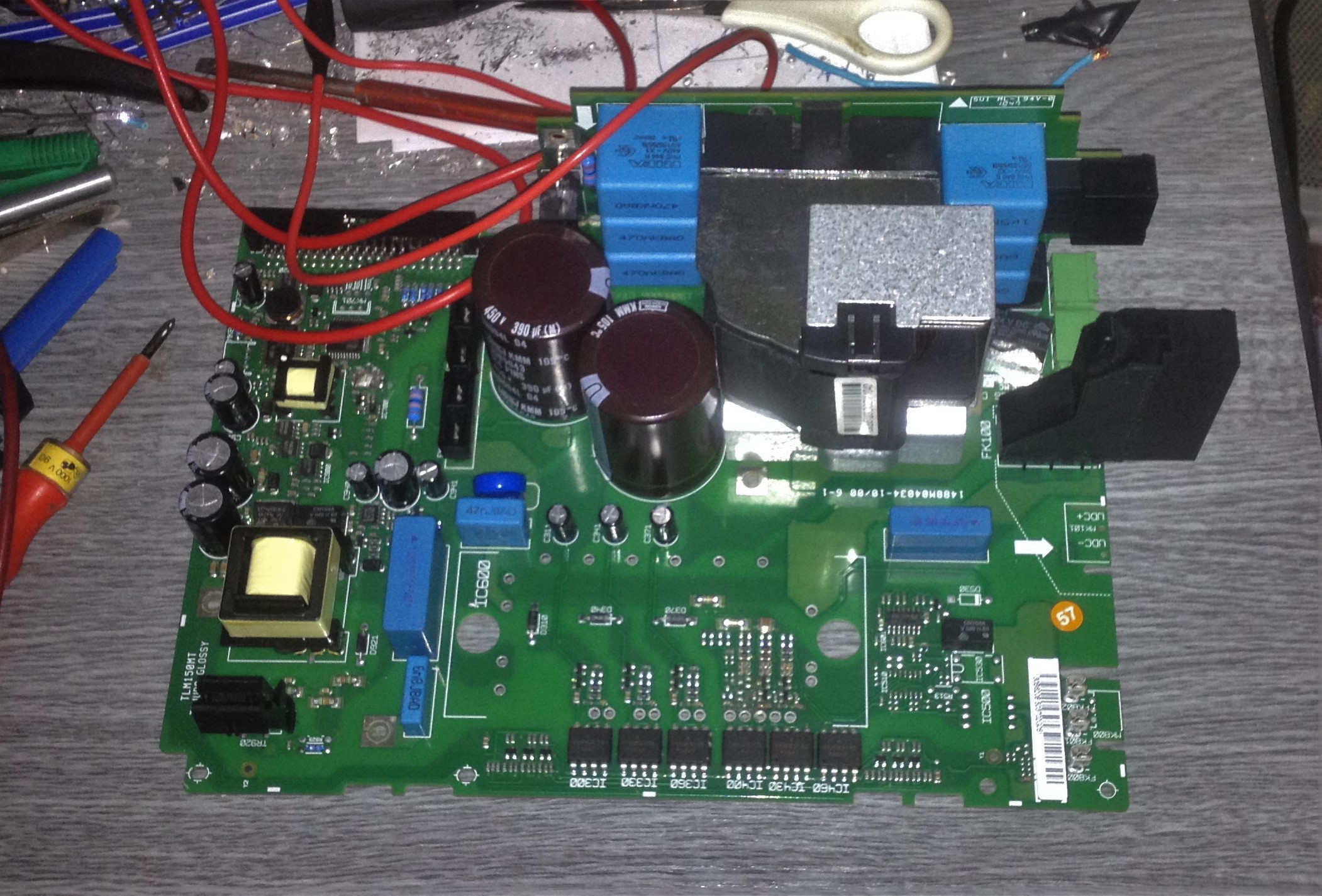
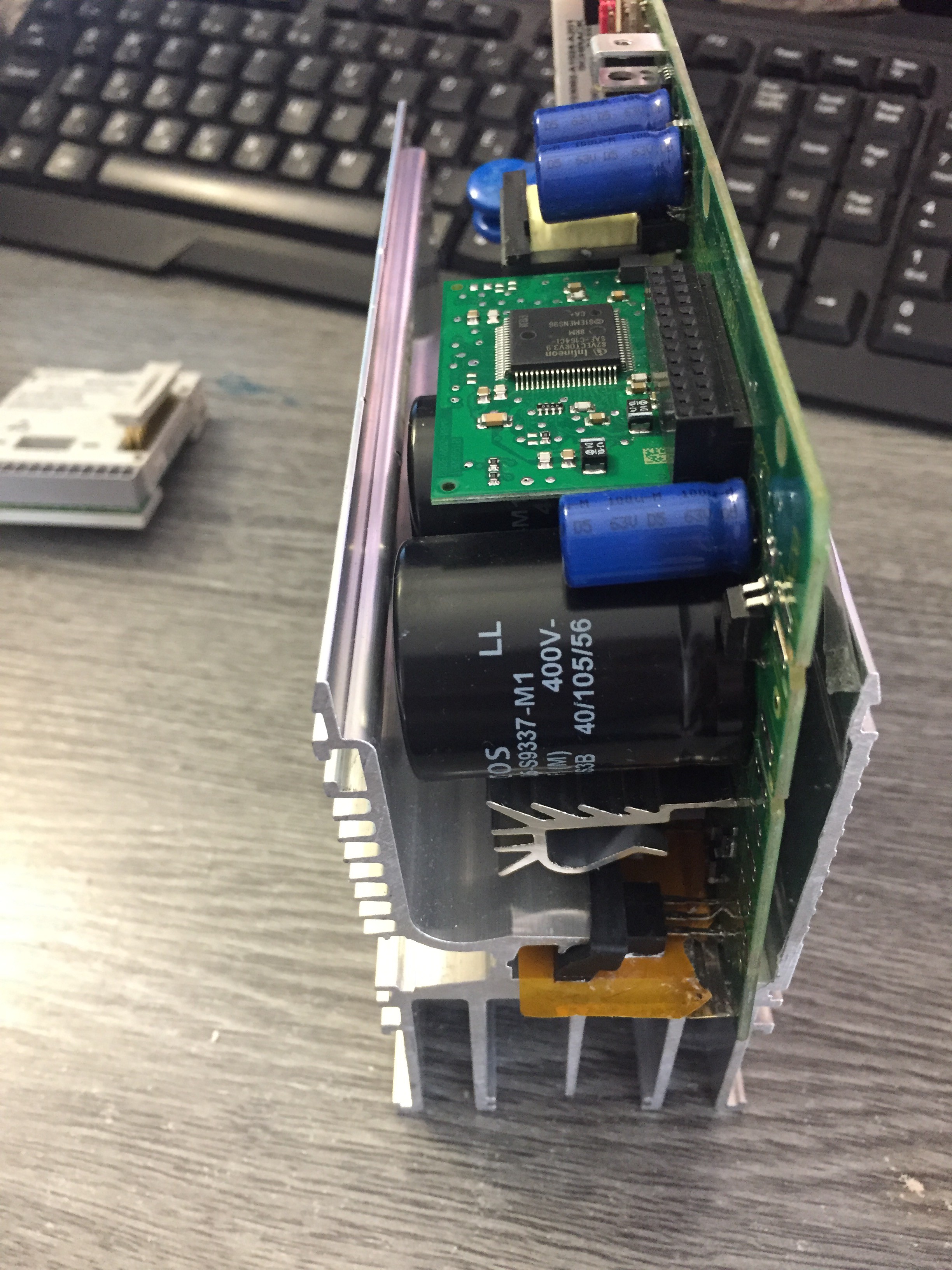
As I mentioned, sometimes you have to disassembly the entier device to measure the power section. It is the power section of the variable frequency drive that I repaired. Up there has the choke and the capacitators, on the left hase the switch mode power supply for the controller board and for the IGBT driver ICs.
The actual power modul already was soldered out from the pcb.
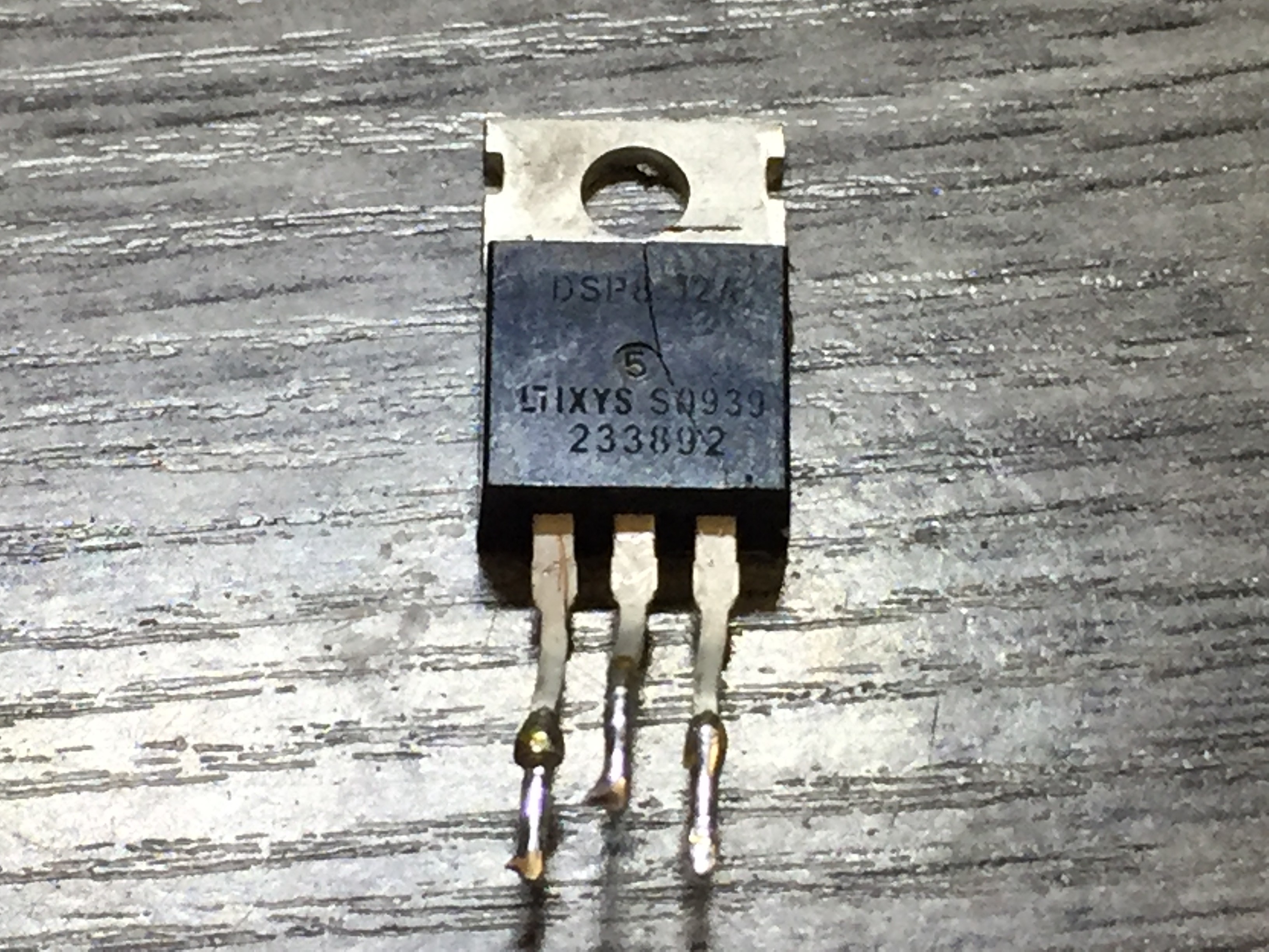
Here it is:
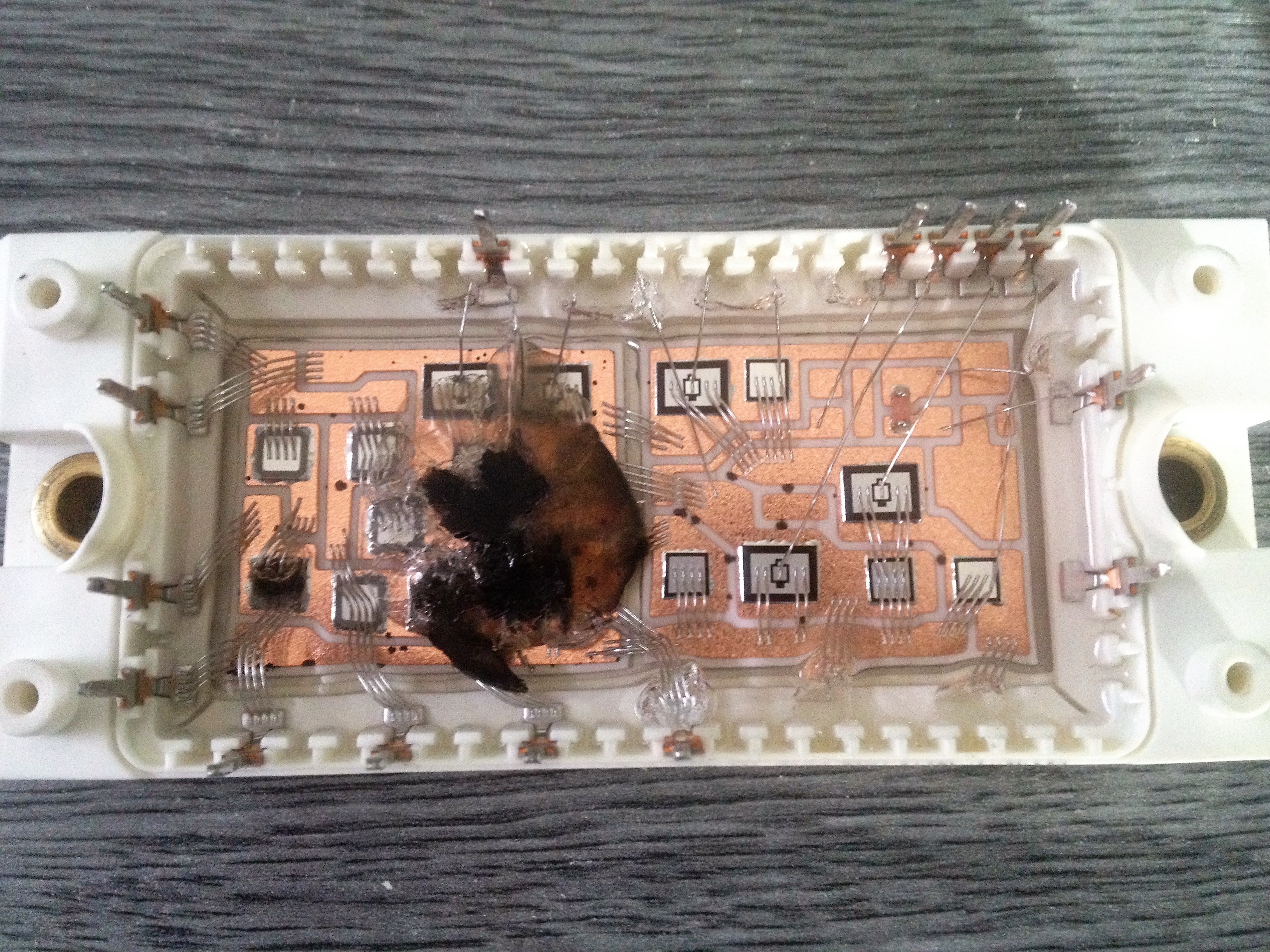 You can see it is an integrated power module, which has all the rectifier diodes and all the IGBTs in one package. This is a more effective way to save space in a drive, so it can be smaller.
These types of modules have some type of silicone that after the damage contains the smoke in it.
After I found the problem, I was seaching for an other power modul, which can substitute mine. I found one on the internet,...
Read more »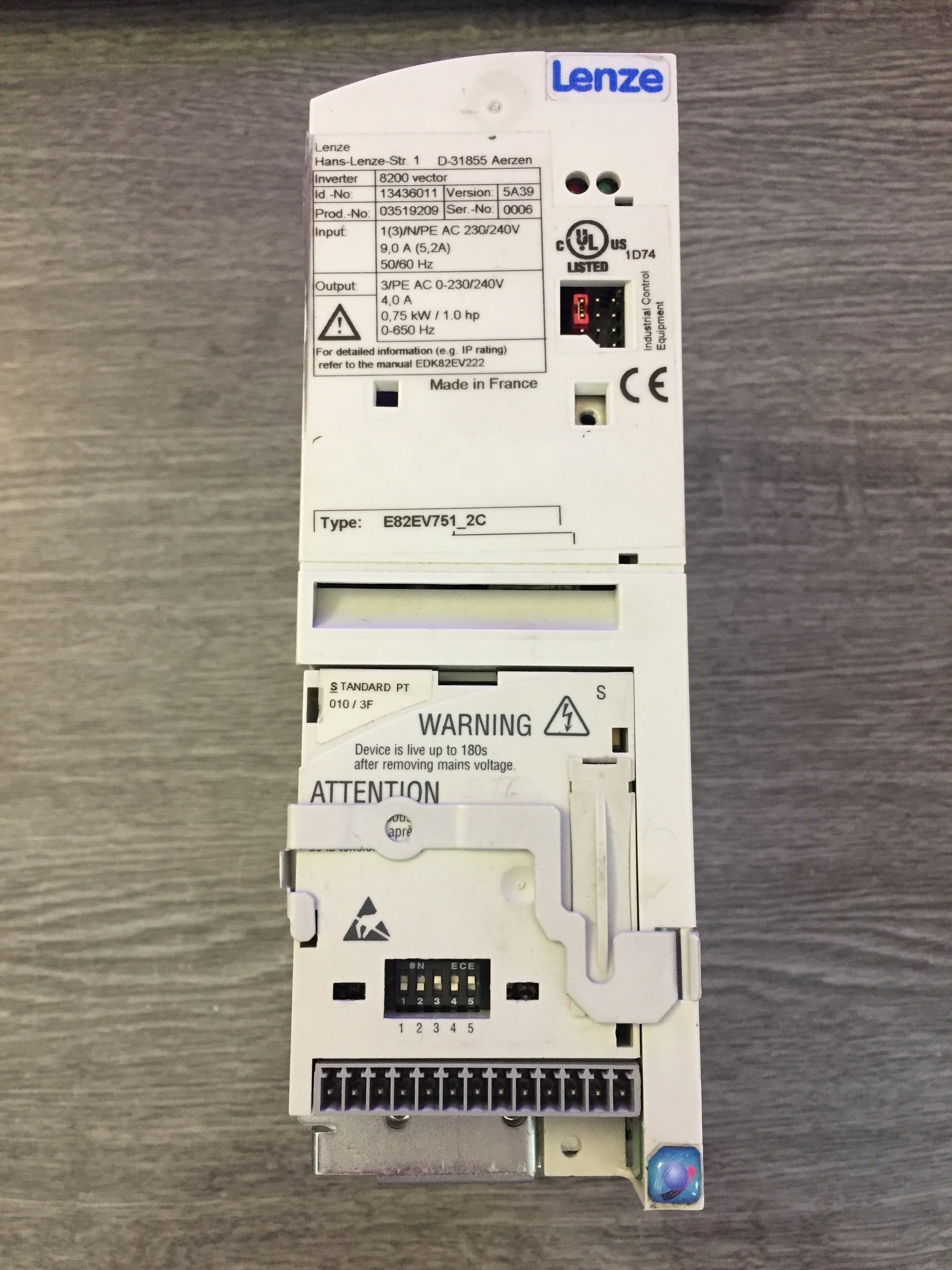


 Paul McClay
 Bud Bennett
 emuboy
hi. Thankyou for your shairing. I want to ask two questions.
1) my vfd gives constantly 540 V from break pins. Which section can I check?
2) My other VFD gives Over voltage fault. What do you think about its problem?
I will grateful if you response my questions.