Close
0%
0%

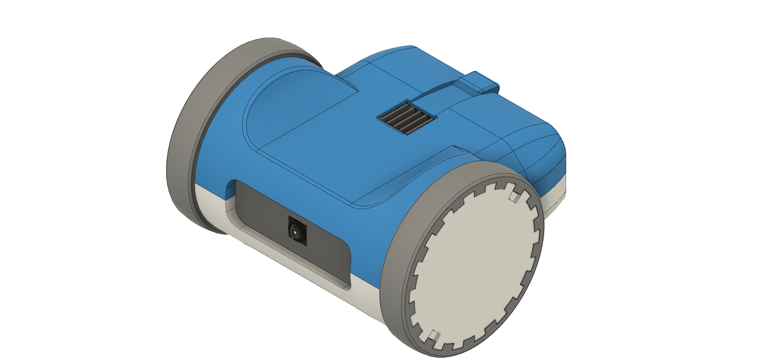
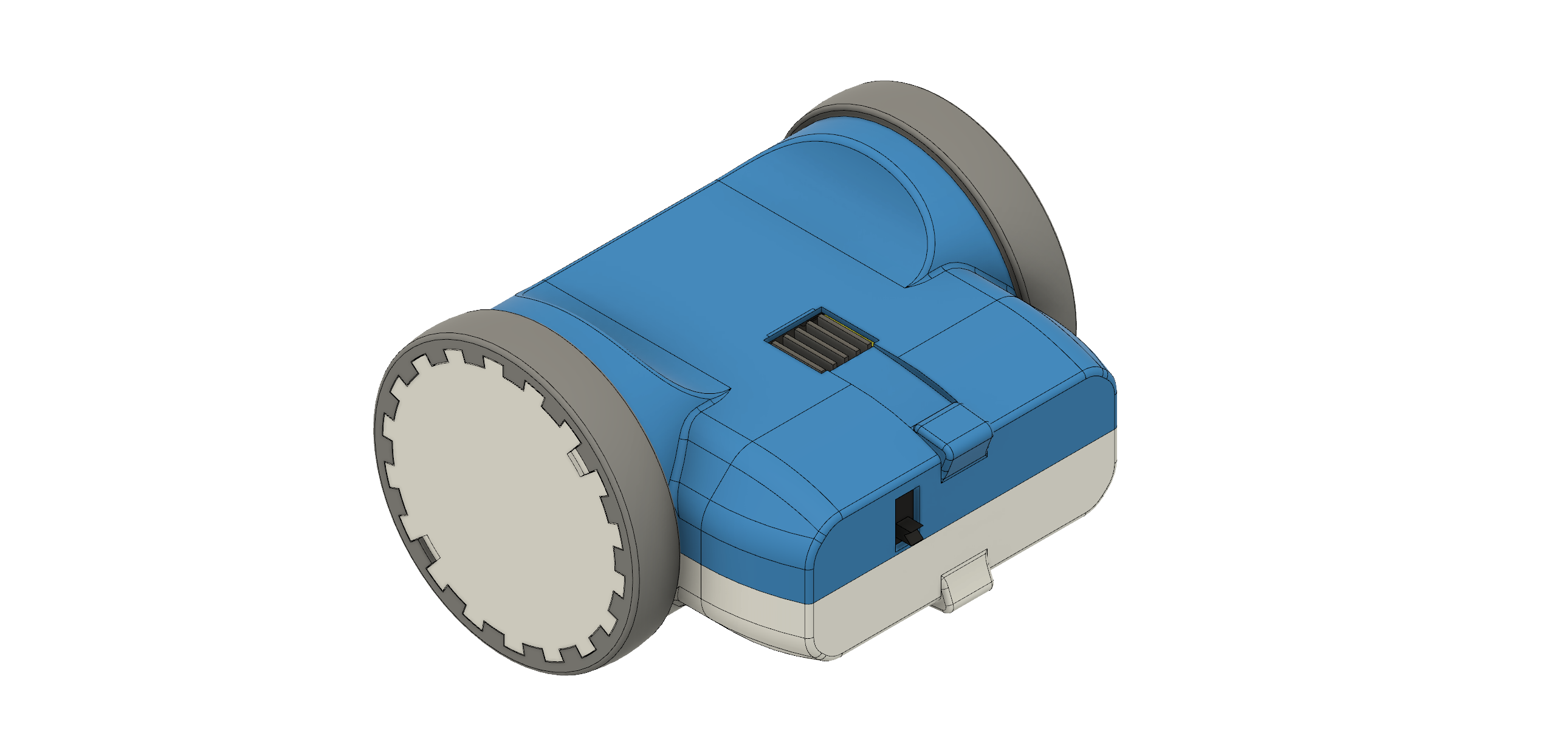
ZeroBot - Raspberry Pi Zero FPV Robot

Raspberry Pi Zero 3D Printed Video Streaming Robot

Similar projects worth following
ZeroBot is a Raspberry Pi Zero W based robot. It can be controlled using any computer or smartphone via a web browser. The integrated camera module makes for a low latency video stream. In addition the Raspberry Pi acts as a Wifi access point, so no router is required. The parts for the hull as well as the wheels can easily be printed on any regular 3D printer.

Some of the key features are:
- Compact CAD design with 3D printed components
- Analog control via a joystick (and multitouch)
- Simple battery solution using only a standard power bank
- Low latency streaming (~0.2s)
- Easy and cheap to build using widely available components

STL files on thingiverse: https://www.thingiverse.com/thing:2352440

View all 7 components

  • How to Get Started (Fall 2018)

    Max.K11/16/2018 at 22:01 5 comments

    For the Zerobot robot there are different instructions and files spread over Hackaday, Github and Thingiverse which may lead to some confusion. This project log is meant as a short guide on how to get started with building the robot. 

    Where do I start?

    1. Grab the STL-files from here: https://www.thingiverse.com/thing:2800717 and print them out following the instructions on Thingiverse
    2. Get the remaining parts: 
      - Raspberry Pi Zero W
      - 2x ICR18650 lithium cell 2600mAh
      - Raspberry camera module
      - Zero camera adapter cable
      - Mini DC dual motor controller
      - DC gear motors
      - ADS1115 ADC board
      - TP4056 USB charger
      - MT3608 boost converter
      - Raspberry CPU heatsink
      - Micro SD card (8GB or more)
      - 2x LED
      - BC337 transistor (or any other NPN) 
      - 11.5 x 6mm switch
      - 4x M3x10 screws and nuts
    3. Wire up the electronics according to this schematic: 
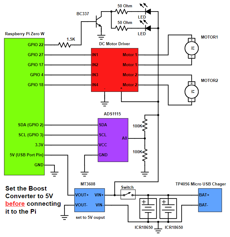
In case you are not familiar with this: The schematic is optimized for readability. You don't have to use this exact wiring (e.g. connection LEDs to ADS1115) as long as the electrical connections stay the same. For the wire gauges, use around 22 AWG wire for the signal connections and slightly thicker wire for the batteries and motors.
    4. The software comes preinstalled on an SD card image. Download it from here: https://drive.google.com/file/d/163jyooQXnsuQmMcEBInR_YCLP5lNt7ZE/view?usp=sharing, extract the files using 7-Zip and flash it to your 8GB micro SD card. Do not boot the Pi before entering your WiFi router name and password in the wpa_supplicant.conf file on the SD.
    5. After the SD card is inserted you can assemble the robot as seem on the pictures on the Hackaday project page. Make sure that all wires are properly isolated. Lithium batteries are very dangerous. If there is a short circuit between the batteries, they can catch fire. 
    6. Turn the robot on and wait for the Pi to connect to your WiFi. After that you can connect to it by accessing its IP followed by the port :3000 like this: 192.168.2.11:3000. If you don't know your Raspberry Pi's IP use a WiFi scanner like "Fing" on your smartphone to scan for devices.
    7. After that you are done! Have fun with your Zerobot! Below are some common questions/problems.

    The robot spins/ doesn't drive right

    The motors might be reversed. You can simply swap the two wires to fix this.

    I can't connect to the Zerobot in my browser

    The Raspberry Pi itself with the SD card image running on it is able to display the user interface in your browser. There is no additional hardware needed, so this can't be a hardware problem. Check if you are using the right IP and port and if you inserted the correct WiFi settings in the wpa_supplicant.conf file.

    I see the user interface but no camera stream

    Check if your camera is connected properly. Does it work on a regular Raspbian install?

    Zerobot and Zerobot Pro - What's the difference?

    The "pro" version is the second revision of the robot I built in 2017, which includes various hardware and software changes. Regardless of the hardware the "pro" software and SD-images are downwards compatible. I'd recommend building the latest version. New features like the voltage sensor and LEDs are of course optional.

    Can I install the software myself?

    If you don't want to use the provided SD image you can of course follow this guide to install the required software: https://hackaday.io/project/25092/instructions You should only do this if you are experienced with the Raspberry Pi. The most recent code is available on Github: https://github.com/CoretechR/ZeroBot

  • The new Zerobot Pro

    Max.K02/20/2018 at 22:02 28 comments

    All new features: More battery power, a charging port, battery voltage sensing, headlights, camera mode, safe shutdown, new UI

    The new software should work on all existing robots. 

    When I designed the ZeroBot last year, I wanted to have something that "just works". So after implementing the most basic features I put the parts on Thingiverse and wrote instructions here on Hackaday. Since then the robot has become quite popular on Thingiverse with 2800+ downloads and a few people already printed their own versions of it. Because I felt like there were some important features missing, I finally made a new version of the robot.

    The ZeroBot Pro has some useful, additional features:

    • Instead of a single battery with a power-bank circuit, the ZeroBot Pro is now powered by two 2600mAh batteries in parallel. Thanks to a cheap TP4056 Micro-USB charger the case does not have to be opened to recharge the batteries. 5V for the Pi and 6V (optional) for the motors are regulated by MT3608 boost converters.
    • Thanks to a ADS1115 ADC the Raspberry can measure the battery voltage and display it on the user interface
    • The entire user interface has been optimized for various screen sizes. There are now buttons for different functions:
      • A photo button for taking pictures in full resolution. This is not as easy as it appears. The stream has to be stopped to start the raspistill application and then restarts.
      • A toggle button to turn the LED headlights on and off. The LEDs are connected via a transistor to an IO pin. (I adopted this idea from franciscorps version of the ZeroBot: https://www.thingiverse.com/thing:2445551)
      • Finally there is a shutdown button that turns the Pi off safely after displaying a confirmation prompt. This should prevent the file system from corrupting
    • The 3D printed parts have been optimized as well to reduce warping and to fit the front panel more easily. 

    If you are interested in building the robot, you can head over here for the instructions: https://hackaday.io/project/25092/instructions 

    The 3D files are hosted on Thingiverse: https://www.thingiverse.com/thing:2800717

    Download the SD card image: https://drive.google.com/file/d/163jyooQXnsuQmMcEBInR_YCLP5lNt7ZE/view?usp=sharing

    After flashing the image to a 8GB SD card, open the file "wpa_supplicant.conf" with your PC and enter your WiFi settings.

  • Easy Setup using SD Image

    Max.K06/24/2017 at 13:07 17 comments

    After a few people ran into problems with the tutorial, I decided to create a less complicated solution. You can now download an SD card image for the robot, so there is no need for complicated installs and command line tinkering. The only thing left is getting the Pi into your network:

    1. Download the image file from here and unzip it to your PC: https://drive.google.com/uc?export=download&confirm=EUSf&id=0B4WbDsFout-NN1M1dzU0elR3NXc
    2. Flash the image to an 8GB or bigger micro SD card with the software of your choice (e.g. Etcher). Don't plug the SD into the Raspberry yet!
    3. In the boot partition of the SD, open the file wpa_supplicant.conf (e.g. using notepad). Change wifi ssid and password to your wifi name and password. The file will be automatically moved to its spot of the Pi's file system on boot. If you make a mistake, you just need to create the file again.
    4. After the Pi has booted up, find out its IP address using your routers interface or through an app like Fing. Connect to this address (e.g. 192.168.2.3) with any browser on your computer

    If you don't want the robot to be restricted to your home network, you can easily configure it to work as a wireless access point. This is described in the tutorial.

    EDIT 29.7. Even easier setup - the stream ip is selected automatically now

  • Introduction

    Max.K05/29/2017 at 20:53 1 comment

    The goal for this project was to build a small robot which could be controlled wirelessly with video feed being sent back to the user. Most of my previous projects involved Arduinos but while they are quite capable and easy to program, there are a lot of limitations with simple microcontrollers when it comes to processing power. Especially when a camera is involved, there is now way around a Raspberry Pi. The Raspberry Pi Zero W is the ideal hardware for a project like this: It is cheap, small, has built in Wifi and enough processing power and I/O ports.

    Because I had barely ever worked with a Raspberry, I first had to find out how to program it and what software/language to use. Fortunately the Raspberry can be set up to work without ever needing to plug in a keyboard or Monitor and instead using a VNC connection to a remote computer. For this, the files on the boot partition of the SD card need to be modified to allow SSH access and to connect to a Wifi network without further configuration.

    The next step was to get a local website running. This was surprisingly easy using Apache, which creates and hosts a sample page after installing it.

    To control the robot, data would have to be sent back from the user to the Raspberry. After some failed attempts with Python I decided to use Node.js, which features a socket.io library. With the library it is rather easy to create a web socket, where data can be sent to and from the Pi. In this case it would be two values for speed and direction going to the Raspberry and some basic telemetry being sent back to the user to monitor e.g. the CPU temperature.

    For the user interface I wanted to have a screen with just the camera image in the center and an analog control stick at the side of it. While searching the web I found this great javascript example by Seb Lee-Delisle: http://seb.ly/2011/04/multi-touch-game-controller-in-javascripthtml5-for-ipad/ which even works for multitouch devices. I modified it to work with a mouse as well and integrated the socket communication.

    I first thought about using an Arduino for communicating with the motor controller, but this would have ruined the simplicity of the project. In fact, there is a nice Node.js library for accessing the I/O pins: https://www.npmjs.com/package/pigpio. I soldered four pins to the PWM motor controller by using the library, the motors would already turn from the javascript input.

    After I finally got a camera adapter cable for the Pi Zero W, I started working on the stream. I used this tutorial to get the mjpg streamer running: https://www.youtube.com/watch?v=ix0ishA585o. The latency is surprisingly low at just 0.2-0.3s with a resolution of 640x480 pixels. The stream was then included in the existing HTML page.

    With most of the software work done, I decided to make a quick prototype using an Asuro robot. This is a ancient robot kit from a time before the Arduino existed. I hooked up the motors to the controller and secured the rest of the parts with painters tape on the robot's chassis:

    After the successful prototype I arranged the components in Fusion 360 to find a nice shape for the design. From my previous project (http://coretechrobotics.blogspot.com/2015/12/attiny-canbot.html) I knew that I would use a half-shell design again and make 3D printed parts.

    The parts were printed in regular PLA on my Prusa i3 Hephestos. The wheels are designed to have tires made with flexible filament (in my case Ninjaflex) for better grip. For printing the shells, support materia is necessary. Simplify3D worked well with this and made the supports easy to remove.

    After printing the parts and doing some minor reworking, I assembled the robot. Most components are glued inside the housing. This may no be professional approach, but I wanted to avoid screws and tight tolerances. Only the two shells are connected with four hex socket screws. The corresponding nuts are glued in on the opposing shell. This makes it easily to access the internals of the robot.

    For...

    Read more »

View all 4 project logs

  • 1
    Installing The Latest Raspbian Image

    DISCLAIMER: This is not a comprehensive step-by-step tutorial. Some previous experience with electronics / Raspberry Pi is required. I am not responsible for any damage done to your hardware.

    I am also providing an easier alternative to this setup process using a SD card image: https://hackaday.io/project/25092/log/62102-easy-setup-using-sd-image

    https://www.raspberrypi.org/documentation/installation/installing-images/

    This tutorial is based on Raspbian Jessie 4/2017

    Personally I used the Win32DiskImage for Windows to write the image to the SD card. You can also use this program for backing up the SD to a .img file.

    IMPORTANT: Do not boot the Raspberry Pi yet!

  • 2
    Headless Setup

    Access the Raspberry via your Wifi network with VNC:

    Put an empty file named "SSH" in the boot partiton on the SD.

    Create a new file "wpa_supplicant.conf" with the following content and move it to the boot partition as well:

    ctrl_interface=DIR=/var/run/wpa_supplicant GROUP=netdev
    update_config=1
    network={
        ssid="wifi name"
        psk="wifi password"
    }

    Only during the first boot this file is automatically moved to its place in the Raspberry's file system.

    After booting, you have to find the Raspberry's IP address using the routers menu or a wifi scanner app.

    Use Putty or a similar program to connect to this address with your PC.

    After logging in with the default details you can run

    sudo raspi-config

    In the interfacing options enable Camera and VNC

    In the advanced options expant the file system and set the resolution to something like 1280x720p.

    Now you can connect to the Raspberry's GUI via a VNC viewer: https://www.realvnc.com/download/viewer/

    Use the same IP and login as for Putty and you should be good to go.

  • 3
    Installing the required software (update 2018)
    sudo apt-get update
    sudo apt-get upgrade
    sudo apt-get install apache2 node.js npm
    git clone https://github.com/CoretechR/ZeroBot Desktop/touchUI
    cd Desktop/touchUI
    sudo npm install express
    sudo npm install socket.io
    sudo npm install pi-gpio
    sudo npm install pigpio
    

    Run the app.js script using:

    cd Desktop/touchUI
    sudo node app.js

    You can make the node.js script start on boot by adding these lines to /etc/rc.local before "exit 0":

    cd /home/pi/Desktop/touchUI
    sudo node app.js&
    cd

    The HTML file can easily be edited while the node script is running, because it is sent out when a host (re)connects.

View all 7 instructions

Enjoy this project?

Share

Discussions

F. Javier wrote 10/25/2019 at 19:12 point

Hi.
I am finishing mounting the ZeroBot Pro, but I have 2 problems:
The first is that when I'm going to move it, so that it moves forward, in the interface, I have to do it to the left, back, to the right, it's as if it was changed.
And the second problem is the LEDs (5mm white) of the headlights, I connect it according to the diagram (or I think), ADS1115 with 100k resistance to the positive of the driver motor and that same cable to a negative of a led (another cable will join the negative poles of the 2 leds). The positives of the LEDs with 50ohm resistors, join and go to the collector pin of the BC337 transistor, the emitter pin of the BC337 to the battery negative and the base pin with a resistance of 1.5k to the gpio22 of the Raspberry.
I do not find where the problem is in the assembly, to see if you can help me.
Thank you.

  Are you sure? yes | no

Max.K wrote 10/27/2019 at 13:33 point

You need to swap the motor wires to change the direction. Alternatively you can change this in software by modifying the app.js file that's on the TouchUI folder on the desktop of the Raspberry pi (access it through VNC viewer for example).

The ADS1115 is for measuring the battery voltage, it has nothing to do with the LEDs. The two 100k resistors form a voltage divider to reduce the voltage that the ADS1115 sees.

The description of your wiring seems alright. If you have a multimeter you can check if gpio22 is being toggled by the led button. Maybe you selected the wrong pin.

  Are you sure? yes | no

F. Javier wrote 10/27/2019 at 15:08 point

Thanks for your reply Max.

I have measured with a multimeter the gpio22 when I activate the LEDs from the TouchUI, current arrives, so the gpio is correct. But I still can't find a way for the LEDs to connect. The positive poles go with diodes to the BC337 pin collector. The negative poles of the LED where they connect? I think the fault may be there.
I have connected via VNC, in the app.js file what would be the line to modify? When I give it to the left it goes forward and when I give it to the right it goes backwards, it would be to turn the screen 90º to the right hahaha
Thanks for everything.

  Are you sure? yes | no

Max.K wrote 10/27/2019 at 16:32 point

If the robots goes forward when you want to turn right that problably means your left motor is turning in the wrong direction. Try swapping the motor pins by swapping A1 and A2 or B1 and B2:

A1 = new Gpio(27, {mode: Gpio.OUTPUT}),
A2 = new Gpio(17, {mode: Gpio.OUTPUT}),
B1 = new Gpio( 4, {mode: Gpio.OUTPUT}),
B2 = new Gpio(18, {mode: Gpio.OUTPUT});

As for the leds, I'm not sure what the problem is. The led anode is connected to the positive terminal of the battery. If you follow the wiring image it should work.

  Are you sure? yes | no

F. Javier wrote 10/29/2019 at 11:16 point

Thanks for your help Max.

I changed the direction of the motor cables and it already works correctly.
The LEDs of the lights also work, the polarity of the led was incorrectly connected.
Thanks for everything

  Are you sure? yes | no

The Chase Lemon wrote 09/10/2019 at 05:25 point

Hey Max,

Your parts list seems a little out of date. Been trying to find the parts on my own, but as I am somewhat new to the whole electronics game, I am uncertain if the items I am finding on my own are the same items required for the project. Just to be clear, I am making the Twitch Drone version of your bot.

Will these parts work?

https://www.amazon.ca/Electric-Magnetic-Gearbox-Vibration-Products/dp/B07DPNQMXS/ref=sr_1_fkmr0_2?keywords=DC+3V+-+6V+Dual+Axis+Gear+Motor+TT+Motor+For+Arduino+Smart+Chassis+Car&qid=1568091061&s=gateway&sr=8-2-fkmr0

https://www.amazon.ca/Stepper-Controller-Arduino-Mega2560-Duemilanove/dp/B0786L5YPP/ref=sr_1_3?keywords=l298n&qid=1568092762&s=gateway&sr=8-3

and I can't find an appropriate power bank. Cheers mate and love the work you have done.

  Are you sure? yes | no

Max.K wrote 09/10/2019 at 16:48 point

Hi, the motors you found are correct. But the driver is definitely too big for the chassis. The drivers that I'm using are on Amazon.ca as well:

 https://www.amazon.ca/Driver-Module-H-Bridge-Replace-Stepper/dp/B075S368Y2/ref=sr_1_28?keywords=l298n&qid=1568111449&s=gateway&sr=8-28

About the battery: You can either use a single 18650 battery and solder leads to it or buy a cheap power bank that has one in it. If you don't want to use the charging circuit from the power bank you will need a tp4056 USB modul or something similar. You can of course also use any other LiPo battery that fits the chassis. The 18650 cells are just an easily available format.

  Are you sure? yes | no

The Chase Lemon wrote 09/10/2019 at 16:54 point

Appreciate the information

  Are you sure? yes | no

The Chase Lemon wrote 09/23/2019 at 07:04 point

Just realized, you don't actually use the power bank, you take the componants out of the encasing, so with realizing that, would this work? https://www.amazon.ca/Poweradd-Portable-Ultra-Compact-External-compatible/dp/B0142JHOEO/ref=pd_ybh_a_7?_encoding=UTF8&psc=1&refRID=TKXY063E9SQFCYR9SFT5

  Are you sure? yes | no

Max.K wrote 09/25/2019 at 18:59 point

Most of the small, cylindrical power banks should contain a 18650 cell and the necessary electronics to output 5V at a high enough current. As I said you can also use any 3.7V lipo pouch cell and a 5V boost module like this: https://www.adafruit.com/product/2465

  Are you sure? yes | no

The Chase Lemon wrote 10/02/2019 at 00:51 point

So I bought a power bank and tore out the innards, battery and the chip attached to it, could I not just go micro usb to micro usb from the chip attached to the battery to the pi zero? Also, is the motor driver suppose to be wired to the chip attached to the battery as well? cause I do not see a 3.7v output, as shown in your schematics?

  Are you sure? yes | no

Max.K wrote 10/03/2019 at 16:57 point

What I did for the first version of the robot was to attach the motor driver directly to the terminals of the battery (3.7V). The Raspberry Pi is connected to the 5V output (USB A) of the power bank. This was done to get some decoupling between the motors and the Pi. 

  Are you sure? yes | no

Amirulmukmin wrote 07/23/2019 at 16:30 point

hey Max .

I already flash the images on SD card and make a file for ssid and password. just like in instruction. 

But the problem is, my raspberry pi is blinking after booting and i wait for it to apprear on my wifi by using Fing apps..

but i didnt found the ip for my raspberry pi zero w.

can you help me out , Max ? i really need this robot comes alive for my younger sister.

Thanks in advance,

Amirul.

  Are you sure? yes | no

Max.K wrote 07/23/2019 at 18:24 point

Maybe try flashing it again. The wpa_supplicant.conf file should be there already, you only have to enter your WIFI ssid and password. Double check those as well. 

  Are you sure? yes | no

Amirulmukmin wrote 07/23/2019 at 18:27 point

already did that wpa_supplicant.conf .. nevermind. i'm trying to download again your images and flash it using etcher programme.. btw can i flash the new images directly into the same SD card ? cause i see the partition is split up.

  Are you sure? yes | no

Max.K wrote 07/23/2019 at 18:49 point

You should format it again to be safe.

  Are you sure? yes | no

Craig Hissett wrote 07/04/2019 at 00:36 point

Hey Max!

Im looking to use your awesome software to run on a slightly different chassis (a dfrobot Devastator) and use a USB webcam as the source for web feed.

Would there be much to change in the software to use a webcam instead of the Pi cam?

Thanks mate :)

Craig

  Are you sure? yes | no

Max.K wrote 07/04/2019 at 16:31 point

Hi, that's definitely possible and shouldn't be too much work.

You need to change the command to run the mjpg-streamer. Right now the input looks  like this: -i "input_raspicam.so -vf -hf -fps 15 -q 50 -x 640 -y 480"

You will have to specify the plugin "input_uvc.so" for a USB cam.

I don't have a webcam to test but there are lots of forum posts about using the mjpg streamer with a USB webcam.

  Are you sure? yes | no

Craig Hissett wrote 07/04/2019 at 16:34 point

hero - thanks matey!

I'll have a look at this over the weekend. I'm excited! :)

  Are you sure? yes | no

Craig Hissett wrote 07/10/2019 at 15:58 point

I've just got a Pi Camera for quite cheap :-)

Going to try this image again; I've written it to two Micro SD cards so far and it seems to have killed them (can no longer format). I think that's just bad luck on the Card front ha ha.

I'm tempted to use a 3B for the build, as I think the USB ports will come in handy on a chassis that size. I'd love to add more to the platform once I've got it tearing around the office, blinking some red eyes :-)

  Are you sure? yes | no

Werner wrote 07/05/2019 at 15:14 point

That's a pretty cool chassis indeed!

  Are you sure? yes | no

Craig Hissett wrote 07/05/2019 at 16:21 point

It's an awesome chassis; plenty of space and amounting points to make something brilliant.

I'm looking forward to tinkering with the software over the weekend :)

  Are you sure? yes | no

Werner wrote 06/30/2019 at 18:14 point

@Max.K, found this to be an interesting alternative for the TP4056 & MT3608 because it integrates both in a nice board w/ a holder for 2x 18650 batteries. I will order a couple these, and work the ZeroBot enclosure to fit it in. It can deliver 5V up to 3A (Max) output current. Very sleek indeed.

https://www.ebay.com/itm/3V-5V-18650-Battery-Shield-V8-Mobile-Power-Bank-for-Arduino-ESP32-ESP8266-Wifi/312439652582

  Are you sure? yes | no

Max.K wrote 07/04/2019 at 16:23 point

Very nice indeed, good find!

  Are you sure? yes | no

Craig Hissett wrote 07/10/2019 at 16:01 point

This looks pretty awesome! My devastator platform is rocking 6v motors, so going to look for something similar to this which will give a regulated 5v and also  a raw output too.

  Are you sure? yes | no

Amirulmukmin wrote 06/19/2019 at 12:43 point

im so confused with instruction  after setup the ssh wifi. they said this

Only during the first boot this file is automatically moved to its place in the Raspberry's file system.

After booting, you have to find the Raspberry's IP address using the routers menu or a wifi scanner app.

Use Putty or a similar program to connect to this address with your PC.

After logging in with the default details you can run

can you guys help me with this ?

Thanks in advance :)

  Are you sure? yes | no

Max.K wrote 06/19/2019 at 14:05 point

Have you tried using the SD card image? It is super easy compared to the manual install process.

  Are you sure? yes | no

Amirulmukmin wrote 06/19/2019 at 14:45 point

already done flash images to the SD card and done change the ssh wifi and password using notepad.. next what should i do ? put the sd card into raspberry pi ? and then turn on the robot ? and one more thing. can i use the circuit that have the LED infront as the headlight with out the LED? 

Thanks for replying me

  Are you sure? yes | no

Max.K wrote 06/19/2019 at 15:32 point

Sorry, I thought you were trying the manual install.

Here is an updated tutorial for the SD card method: https://hackaday.io/project/25092-zerobot-raspberry-pi-zero-fpv-robot/log/156016-how-to-get-started-fall-2018

After you have inserted the sd and turned on the raspberry pi it will try to connect to your wifi network. You then have to find out its IP address. You can install Fing on your smartphone and scan the wifi for ip addresses. It will show the Raspberry Pi if it successfully connected.

  Are you sure? yes | no

Amirulmukmin wrote 06/19/2019 at 15:50 point

alright.. i got all the image flashed in SD card .

Then , i make the changes in the ssh wifi name . i edit with notepad to change the ssh wifi to my home wifi network. 

then what should i do ? put the SD card on my robot and boot it up right away ? and i should do anythings with this ? ( see below )

<<<<

Access the Raspberry via your Wifi network with VNC:

Put an empty file named "SSH" in the boot partiton on the SD.

Create a new file "wpa_supplicant.conf" with the following content and move it to the boot partition as well:

>>>>

sorry cause i trouble you sir.

  Are you sure? yes | no

Max.K wrote 06/19/2019 at 16:12 point

No problem. If the wpa_supplicant.conf and the empty ssh file is on there, you can just boot it up. If you made a mistake you can always simply flash the image again.

  Are you sure? yes | no

EdwardChew wrote 05/22/2019 at 07:55 point

Hi bro. Like to let you know that the image works on the Raspberry Pi 3 Model B V1.2! Streaming, voltage & temperature display, light control. Yes!
So im designing a cool rover to fit the bigger board.
Can i parallel extra 1 more LED to each of the 2 LEDs? any value i need to change? * update yes can

I saw your reply to someone bout changing the resolution, i tried sudo nano /etc/rc.local and start.stream.sh but no parameter bout the resolution there though

  Are you sure? yes | no

Max.K wrote 05/25/2019 at 16:41 point

Good to know that it works. I am pretty sure the resolution is set in the start_stream.sh script on the desktop (it's 640x480):

https://github.com/CoretechR/ZeroBot/blob/master/start_stream.sh

  Are you sure? yes | no

EdwardChew wrote 05/27/2019 at 02:31 point

ok bro. what do i type to get in ya? not familiar with raspberry coding. i tried sudo nano start_stream.sh but nothing there. or anything i missed?

  Are you sure? yes | no

Max.K wrote 05/27/2019 at 19:04 point

If you are on the desktop via CNV viewer, just open the TouchUI folder and right click the file to open it with a text editor. Sudo nano works too, you just have to navigate to the folder using "cd" to change the directory like "cd Desktop" and "cd TouchUI".

  Are you sure? yes | no

EdwardChew wrote 06/10/2019 at 09:04 point

ok what works for me was cd Desktop > cd touchUI > sudo nano start_stream.sh

And since i run RP3 with it so i designed a new body. Posted here with link back to your project here.
https://www.thingiverse.com/thing:3671909

Thanks man 

  Are you sure? yes | no

EdwardChew wrote 06/04/2019 at 08:58 point

Hi bro. For both cd Desktop and cd TouchUI, it says no such file or directory.  :-(

  Are you sure? yes | no

Max.K wrote 06/05/2019 at 15:47 point

You don't need that console commands if you are using VNC viewer. Have you tried it?

  Are you sure? yes | no

raedrik wrote 03/11/2019 at 23:35 point

Got everything wired up per the pro schematic and am using the supplied image. My right  motor will not run in reverse or run in reverse when turning right; it runs forward correctly when selecting forward or left on the touch/mouse controls. Any ideas of what could cause this issue? Tried swapping the motors with same result.

  Are you sure? yes | no

Max.K wrote 03/16/2019 at 10:21 point

Try swapping the wires that run between the Rapi and the motor driver. If the motor still only goes forward, the driver might be broken. If not, you might be using the wrong output pin on the Raspi.

  Are you sure? yes | no

[deleted]

[this comment has been deleted]

Max.K wrote 03/03/2019 at 18:03 point

I know that the image doesn't work on the 3B+, it will probably be the same for the A+ as it was introduced even later. You can try to do the manual setup though.

  Are you sure? yes | no

Olivier Michel wrote 01/31/2019 at 17:54 point

Would it be possible/easy to use a Raspberry Pi 3 Model A+ instead of the Raspberry Pi Zero W? I guess I would only need to move the screw holes to accommodate for the size of the Pi 3, right?

  Are you sure? yes | no

David Wilson wrote 01/28/2019 at 18:14 point

Sorry if this has been discussed previously, I could not find any mention of the following three topics:

1. Video recording capabilities 

2. Mobile Hotspot (on-board plug-and-play internet source)

3. camera tilt actuator for panning the camera.

I saw this and I immediately thought....Police tossing this into a building prior to the swat team moving in. I work for a local government and would love to make one of these for our local police department. 

any advice is helpful!

  Are you sure? yes | no

Max.K wrote 01/29/2019 at 09:51 point

1. It should be possible to record the stream from the Raspberry Pi itself: https://github.com/cncjs/cncjs/wiki/Setup-Guide:-Raspberry-Pi-%7C-MJPEG-Streamer-Install-&-Setup-&-FFMpeg-Recording

2. The Raspberry can run in AP mode, but this has to be configured first: https://howtoraspberrypi.com/create-a-wi-fi-hotspot-in-less-than-10-minutes-with-pi-raspberry/

3. You could use a cheap hobby servo to pan the camera. In the User interface you can add a second joystick. I was asked about this before and shared the code for it: https://hackaday.io/project/25092-zerobot-raspberry-pi-zero-fpv-robot/discussion-108786

Using the robot for the Police sound very cool, I wouldn't recommend throwing it though. :)

  Are you sure? yes | no

chadk5utc wrote 01/23/2019 at 00:27 point

Hi Max 

 I have been reading and researching more of the code and understanding more of it however still unable to make it work with Sabertooth2x32. You mentioned changing two lines of code to make it work? I wondered if you would point them out? On another note would this work as well on Pi3?  my cats and dogs not sure what to think of the little Zerobot pro following them about the house. Thanks 

  Are you sure? yes | no

Max.K wrote 01/23/2019 at 10:49 point

I just had a look at the sabertooth 2x32 manual and I have a solution: You can set the dip switches in a way that the S1/S2 analog inputs control the motor speed and A1/A2 control the direction. According to the manual you need to set the dip switches to "independent mode" and "single direction mode". Then you need to modify the code like this:

var Gpio = require('pigpio').Gpio,
  S1 = new Gpio(27, {mode: Gpio.OUTPUT}),
  A1 = new Gpio(17, {mode: Gpio.OUTPUT}),
  S2 = new Gpio( 4, {mode: Gpio.OUTPUT}),
  A2 = new Gpio(18, {mode: Gpio.OUTPUT});
  LED = new Gpio(22, {mode: Gpio.OUTPUT});

io.on('connection', function(socket){
  console.log('A user connected');
  
  socket.on('pos', function (msx, msy) {
    msx = Math.min(Math.max(parseInt(msx), -255), 255);
    msy = Math.min(Math.max(parseInt(msy), -255), 255);
    //S1 and S2 set the speed, A1 and A2 set the direction
    S1.pwmWrite(Math.abs(msx));
    if(msx > 0) A1.digitalWrite(1);
    else A1.digitalWrite(0);
      
    S2.pwmWrite(Math.abs(msy));
    if(msy > 0) A2.digitalWrite(1);
    else A2.digitalWrite(0);

  });

Here's why: Usually you would have four analog inputs on simple dual motor controllers. One for each direction of each motor. That's why in my original code spinning forward means "MA1 = 255, MA2 = 0" and backwards is "MA1 = 0, MA2 = 255". The sabertooth does not work like that. Instead the inputs can be configured so that S1 and S2 control the speed with analog PWM values and A1 and A2 control the direction. In the code the only change needed is to make sure the S1/S2 output is a positive value and A1/A2 is 0 or 1 depending on the direction.

You could also use the bidirectional mode where you don't need A1/A2 at all, so forward is "S1 = 255" and backward is "S1 = 0". The problem is that the motors only stop if the PWM value is exactly in the middle at "S1 = 127,5" or 2.5V which is difficult to archive. If the Raspberry is off that also means the motors might spin uncontrollably. So it's best to use the "single direction mode".

  Are you sure? yes | no

Christer007 wrote 01/21/2019 at 06:25 point

Can you teach me how to use a wifi module for this? I want to control it for up to 100 meters. And also I want to add a thermal camera module for it. I will also replace the default camera with toggle-able IR cut so that it will change when dark and a thermal camera as a backup.

  Are you sure? yes | no

[deleted]

[this comment has been deleted]

chadk5utc wrote 01/06/2019 at 19:01 point

The Pro version uses LED's as headlights and few new addons

  Are you sure? yes | no

jmpv1247 wrote 12/24/2018 at 06:34 point

where to buy

  Are you sure? yes | no

chadk5utc wrote 12/24/2018 at 20:59 point

while I haven't seen this one for sale anywhere there are a number of small inexpensive tank like or car kits one could easily use for a base platform and could easily hold pi zero and batteries. 

  Are you sure? yes | no

Elliot Williams wrote 12/20/2018 at 18:31 point

I _soooo_ need to build this.  I'm adding it to my resolutions for 2019.  (Might as well make them fun, right?)

  Are you sure? yes | no

chadk5utc wrote 12/16/2018 at 20:27 point

I have built and tested this for days and love the project! I do now have questions as I have a similar project currently using r/c receiver connected to my motor controller on a heavier model. Its currently configured to use PWM however I see in yours there are 4 inputs to the motor driver where I only need 2? Left and Right channel  Im not sure I understand the code fully but it appears only 2 wires are used? motor driver Im using is sabertooth 2x32

  Are you sure? yes | no

Max.K wrote 12/20/2018 at 17:06 point

It looks like your motor driver is "smarter" and only needs one PWM input per motor. The driver I'm using has two separate inputs for rotating left or right. You would have to change two lines of code to make the Raspberry Pi work with the sabertooth driver. Is this what you are trying to do or are you going to use an RC receiver instead?

  Are you sure? yes | no

chadk5utc wrote 12/21/2018 at 16:29 point

Hi thanks for the reply , I can currently use R/C on it and Yes I am trying only to modify this to work with sabertooth. I believe changes need to be made withing the following just not sure how:

var Gpio = require('pigpio').Gpio,
  A1 = new Gpio(27, {mode: Gpio.OUTPUT}),
  //A2 = new Gpio(17, {mode: Gpio.OUTPUT}),
  B1 = new Gpio( 4, {mode: Gpio.OUTPUT}),
  //B2 = new Gpio(18, {mode: Gpio.OUTPUT});
  LED = new Gpio(22, {mode: Gpio.OUTPUT});

app.get('/', function(req, res){
  res.sendfile('Touch.html');
  console.log('HTML sent to client');
});

child = exec("sudo bash start_stream.sh", function(error, stdout, stderr){});

//Whenever someone connects this gets executed
io.on('connection', function(socket){
  console.log('A user connected');
  
  socket.on('pos', function (msx, msy) {
    //console.log('X:' + msx + ' Y: ' + msy);
    //io.emit('posBack', msx, msy);

    msx = Math.min(Math.max(parseInt(msx), -255), 255);
    msy = Math.min(Math.max(parseInt(msy), -255), 255);

    if(msx > 0){
      A1.pwmWrite(msx);
     // A2.pwmWrite(0);
    } else {
     // A1.pwmWrite(0);
      A2.pwmWrite(Math.abs(msx));
    }

    if(msy > 0){
      B1.pwmWrite(msy);
     // B2.pwmWrite(0);
    } else {
     // B1.pwmWrite(0);
      B2.pwmWrite(Math.abs(msy));
    }

  });

Wondering if this would get it? may have to try and see

  Are you sure? yes | no

yann R wrote 11/18/2018 at 13:53 point

 Heyyy Max, thank for your sharing. I adapt your project on a lego, as i do not have a printer 3d. i open ports on router its very fun. The next step, makean inductive chargning station for run 24h/24 and modify web page to put the password http://www.instagram.com/p/BqUueMrnLPv/?utm_source=ig_share_sheet&igshid=44scyx7mx4gd

  Are you sure? yes | no

lpaganoo wrote 11/14/2018 at 10:47 point

Hello Max. Your project is really great! I embarked on its construction and I have an error message at the line: "sudo npm install pigpio".
Here it is: "npm WARN engine pigpio@1.1.4: wanted: {" node ":"> = 4.0.0 "} (current: {" node ":" 0.10.29 "," npm ":" 1.4.21 "})

could you help me ?
Thank you

  Are you sure? yes | no

Max.K wrote 11/16/2018 at 20:24 point

Hi, is there a reason you are doing the manual install? There are fully finished and tested SD-card images that are very easy to use: https://hackaday.io/project/25092-zerobot-raspberry-pi-zero-fpv-robot/log/97988-the-new-zerobot-pro

  Are you sure? yes | no

lpaganoo wrote 11/17/2018 at 20:46 point

Hi Max, thank you for your answer and for your work with this robot. In fact I am a total beginner in the field of Rpi and I wish, by this construction, to train me. Your explanations are very detailed and what gives me the information to learn ;-) I will still test the version "turnkey" because I can't wait to test the editing.
Thanks again

  Are you sure? yes | no

grobi_schalenelli wrote 11/06/2018 at 14:57 point

339/5000

Hello, a great project. My ZeroBot works wonderfully. However, I have no housing, but looks good too.
I control the ZeroBot on the way normally over the Browser. You just have to establish a VPN connection to the home router. Works wonderfully. Or only the camera stream on the port release of port 9000.

  Are you sure? yes | no

Similar Projects

Does this project spark your interest?

Become a member to follow this project and never miss any updates