 Bud Bennett
[Edit 2019-11-15: This is becoming the never-ending project. I have been prodded by several people that want to extend the design to work with a stack of supercapacitors. I had no need for that, so I did not put any effort to insure the functionality of a stack, other than allowing for it by programming some component values on the PCB. But since the capability is there it should function correctly. I'll be trying to implement the dual supercapacitor functionality over the next few days/weeks.]
I have 3 Raspberry Pi computers running 24/7 in headless mode scattered around my residence. One of them is an old Pi1B that manages my heating system and monitors my water well. I consider it a mission critical piece of hardware. Invariably, when I leave for a trip in the winter the power will fail, so I need a means to automagically and gracefully shutdown all of the headless Pi’s.
I built a working UPS using a stack of two 400F supercapacitors about three years ago: https://www.raspberrypi.org/forums/viewtopic.php?f=37&t=50470&hilit=controlled+shutdown&start=25. It was a relatively simple solution that did not make very efficient use of the supercaps, but now with more power hungry versions of the Raspberry Pi I decided it was time to build a new one with higher load capacity (and re-purpose the supercaps).
The energy that you can get from a capacitor is simply
where V1 is the initial voltage across the capacitor and V2 is the final voltage across the capacitor. The output energy is in Joules (Watt-seconds). It is evident from this equation that you can get much more energy out of the capacitor if you can get a lot of voltage across it and take more voltage from it. The problem is that affordable supercaps don’t exist with voltage ratings above 3V (typically 2.7VDC).
So just stack them like batteries then. What’s the big deal? When you stack two identical capacitors in series you get half the capacitance value. This is actually not as bad as it sounds since your energy capacity goes up with the square of the applied voltage. So if we had a stack of 4 supercaps that we could put 10V across would produce 4X more energy than a single supercap with 2.5V across it. Or conversely, you could use smaller supercaps to get the same energy output. The basic problem with this thinking is that the prices of supercaps don’t scale linearly with size — a 400F is $12 while a 100F is $8-$12, so 4 of them will cost a lot more. Another issue with stacked supercaps is one of balancing. The capacitor voltages need to be kept in balance to avoid exceeding the rated voltage. This requires extra circuitry, cost and complexity in the charging circuitry.
My heating system only needs backup power long enough to shutdown the system — a last gasp.
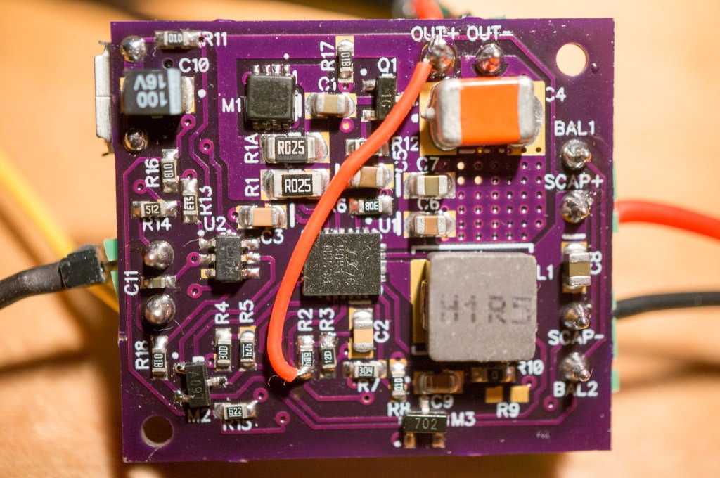
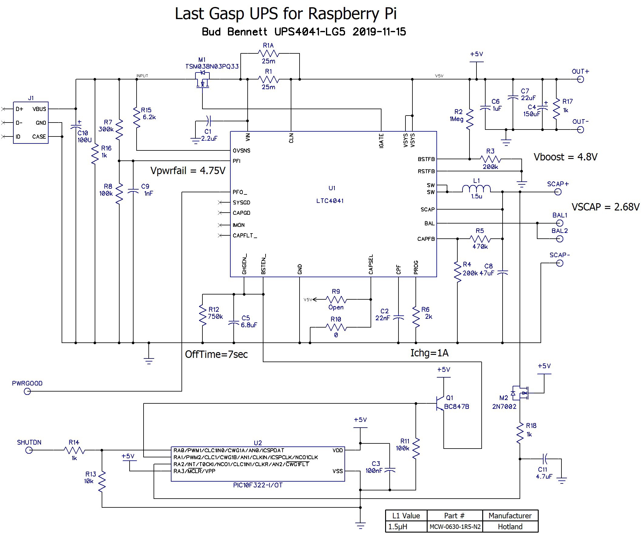
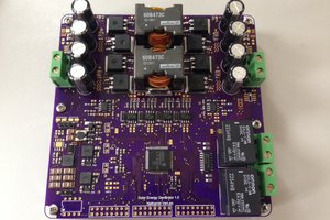
The current design:
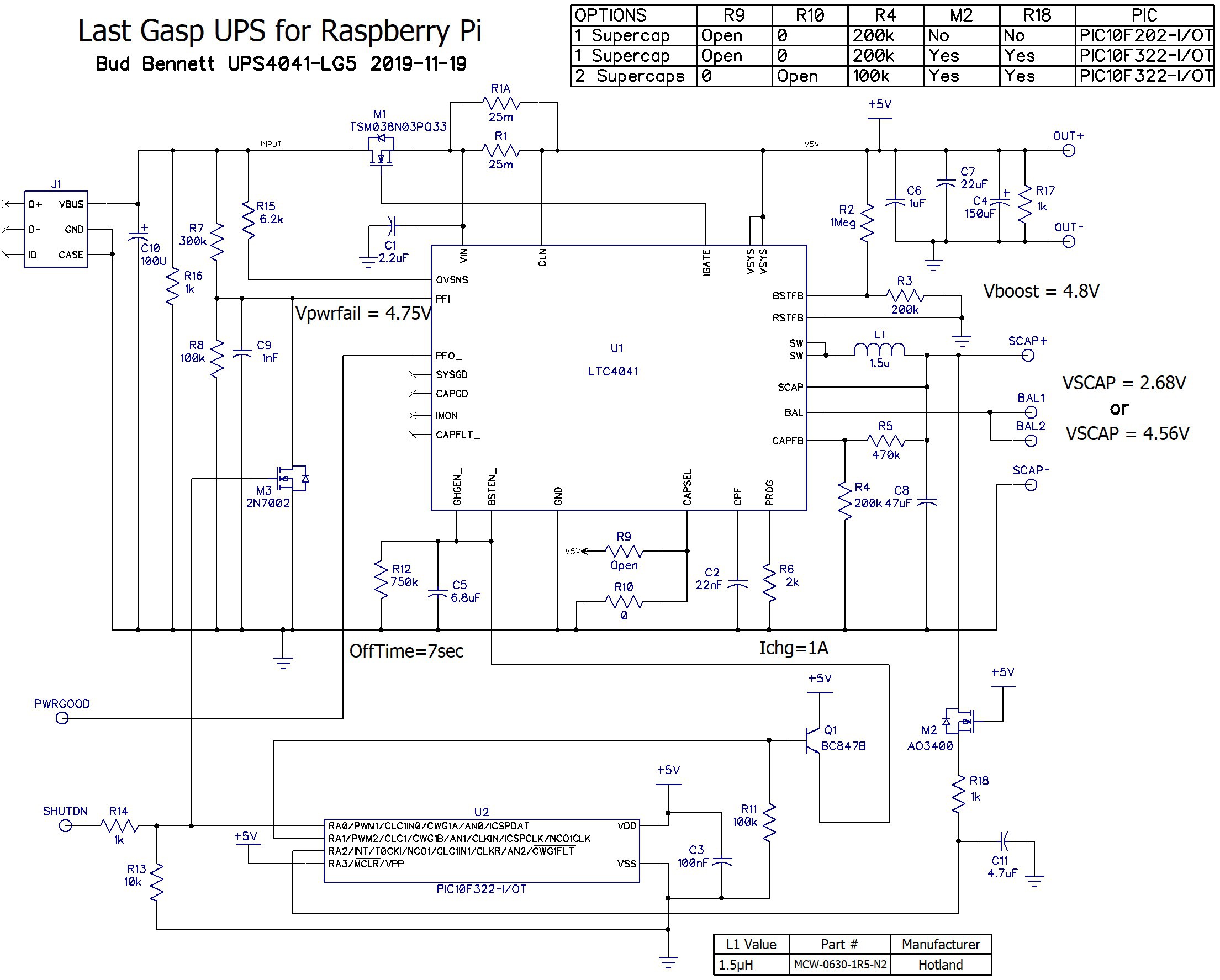
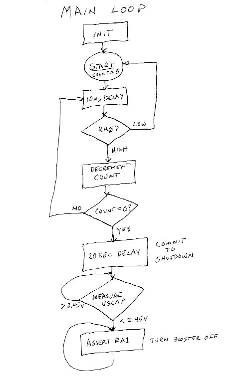
Analog Devices recently (as of 2018-10-1) released the LTC4041, a supercapacitor backup IC. It takes care of the charging of the supercapacitor and the balancing, if there are two of them. It also manages the switchover from powering the load from an AC source to powering the load from the supercapacitor backup. What it doesn't manage is the timers required for the interval when the Raspberry Pi is committed to shutting down and the power-off interval which resets the Raspberry Pi and allows it to reboot when AC power becomes available again. This is the required functionality of the design:
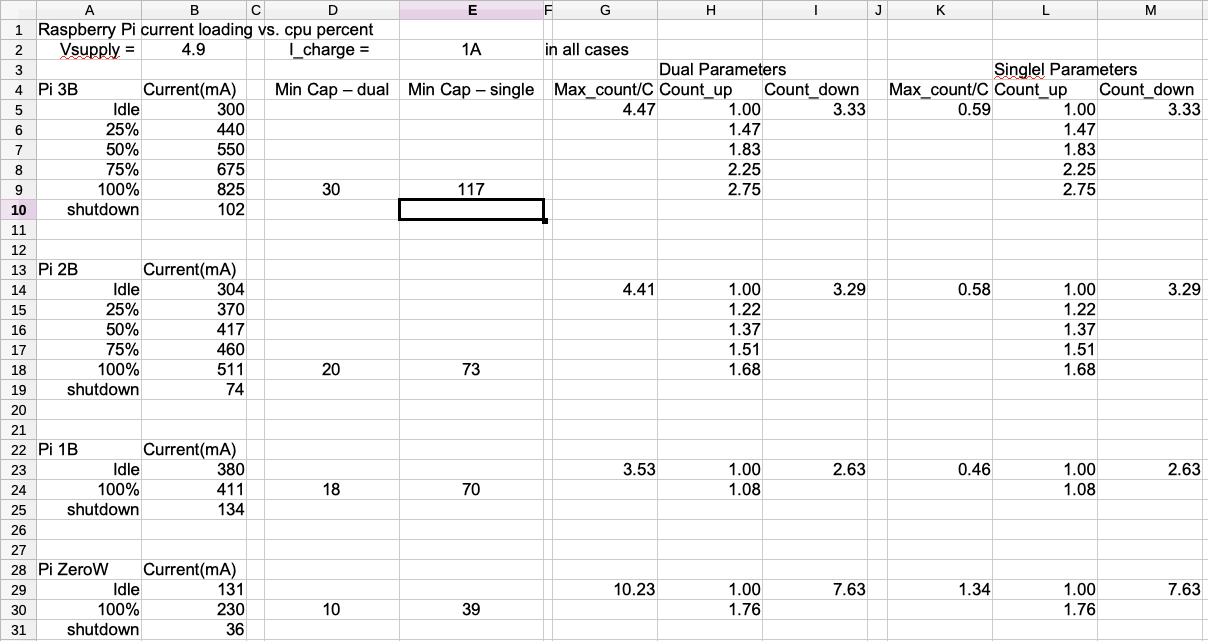
- Provide 5V±0.25V power to the RPi @ 500mA to 2A max.
- If the power fails, continue to provide 5V from a single (or dual) SuperCap charged to 2.7V (or 5V). And indicate the power failure to the RPi.
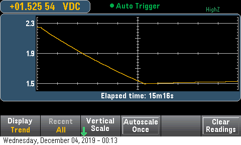
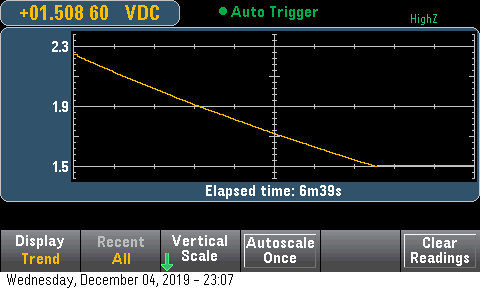
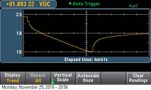
- Backup power must be provided for a minimum of 35 seconds. The current load will be high until the RPi shuts down into a low current state that only draws about 50-80mA. It takes about 10-20 seconds to enter the shutdown state.
- The RPi will assert a SHUTDN input to indicate to the UPS that it has committed to the shutdown sequence. The UPS must provide backup power for 15-20 seconds after the SHUTDN...


 Nathaniel VerLee
 Patrick Van Oosterwijck
 alcor6502
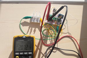
Hello Bud,
Hopefully, final last question from me.
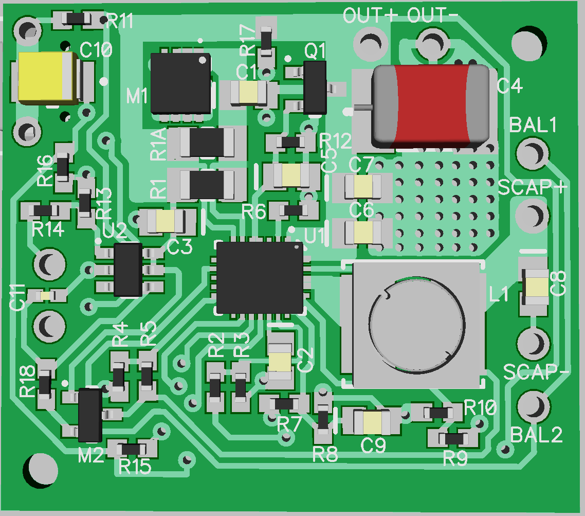
I have finally built one unit, plan to build 3. Although difficult to do with micro smd components but I managed to do a reasonable job first time paste soldering this small of components. Im not sure how to tell if the chips are soldered correctly but that leads me onto the, hopefully, final question.
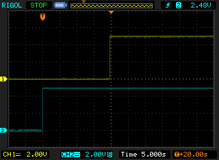
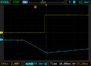
1) What is the best way of testing the board. Presuming to leave the supercap off first, just power it up and test various voltages?
Any ideas appreciated.
Thanks,
Rob