 Bud Bennett
I received a junk email from Analog Devices (they absorbed Linear Technology a short while ago) with a teaser about a new super capacitor backup IC -- the LTC4041 -- claiming to provide a 2.5A backup booster and buck-mode super capacitor charger for a single or dual super capacitor stack. I was intrigued. After downloading the data sheet, and understanding it somewhat, I decided to try to implement the Last Gasp UPS using the LTC4041 as the main ingredient.
I spent a couple of days ruminating about how to make it work as a Last Gasp UPS for the Raspberry Pi. The schematic below is my first attempt. If it works out, I'll build a couple PCB prototype boards to test the concept.
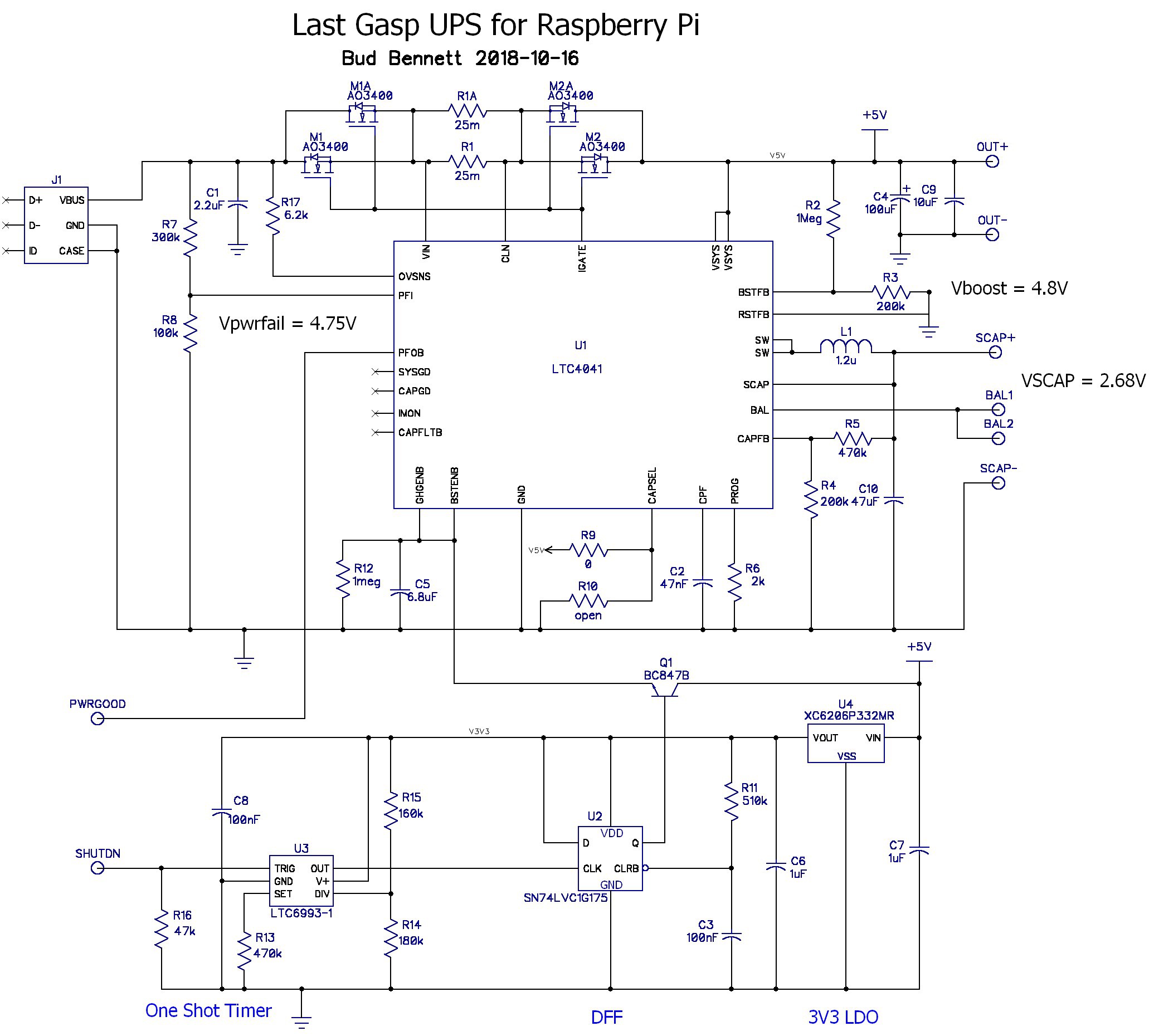
The circuit above (see this project details for the latest schematic) reflects what I have in my current inventory. I'm using AO3400 NCH FETs as the input switches because they are already in my inventory and really cheap at about $0.03/each. R1 is split into two components because I don't have a 12.5mΩ power sense resistor, but I do have 25mΩ 1206 sense resistors. The inductor, L1, is the same as what I bought before -- a CoilCraft MLC1260-122ML -- which is bigger than what Analog Devices recommends, but I can't get it because Digikey doesn't stock it.
Circuit Operation:
Normally, the input power is connected to the load by the two inputs switches, M1-M2. The super capacitor backup source is charged to either 2.7V (single SCAP) or 5V( dual SCAPs). The final voltage on the supercap(s) is determined by R4-R5. The CAPSEL pin selects programs the LTC4041 for either one or two supercaps. If there are two supercaps the charger automatically balances the voltage across them. The charge current is set to 1A by R6. If the sum of the charger and load currents exceeds 2A, set by R1, then the charge current is reduced until the sum of load plus charge currents is 2A. This is to avoid overloading the input power source.
The LTC4041 detects when the input voltage drops below 4.75V, set by R7-R8, and then disconnects the input switches (M1-M2) from the load. It also activates the boost converter to provide 4.8V to the load, using the stored energy on the super capacitor(s). The output voltage is set by R2-R3. If the input power becomes available again the LTC4041 automatically disables the booster and reconnects the load to the input. Without any intervention the boost converter would try to keep the load voltage at the programmed setting until the voltage on the super capacitors(s) was too low, then eventually drop the load voltage as the super capacitor backup voltage decreased to a point where it couldn't sustain the output power.
The added circuitry communicates the loss of power to the Raspberry Pi (the load), and then initiates a shutdown sequence after the Raspberry Pi indicates that it is committed to a shutdown sequence by asserting the SHUTDN input. The SHUTDN input triggers a oneshot timer that keeps power applied to the load for about 15-20 seconds (while the RPI shuts down its running processes). At the end of the one shot interval the DFF is clocked to a high state, which pulls the BSTENB and CHGENB pins to about 2.8V via the emitter of Q1. The LTC4041 goes into a shutdown state at this point and disconnects the input switches, M1-M2, and disables the booster letting the output voltage fall to zero. The voltage on the BSTENB and CHGENB pins floats slowly back down with a time-constant determined by R12-C5. When the voltage drops below 1.4V the LTC4041 is re-enabled to resume normal operation. If the voltage at SCAP is below 2.5V and the input voltage is low then the LTC4041 remains in a shutdown state until the input voltage rises above 4.75V.
When input power becomes available again the load is reconnected and the Raspberry Pi reboots. Then the cycle repeats.
A few things to worry about:
- This project is billed as "A single supercapacitor ...", but this chip has all of the equipage to handle one or two super capacitors. So why not? I left options to use 2 supercaps in the circuit. If 2 supercaps are used, then make sure that the voltage on the SCAP pin has discharged below 2.5V when the one-shot timer expires or else the booster could be re-enabled and reboot the Raspberry Pi even if there is no input power applied. Whether that is a bad thing or not is up to you.
- There is a race condition when the LTC4041 is disabled at the end of the one-shot interval. Q1 is attempting to pull CHGENB and BSTENB to 2.8V while the booster is disabled and the output voltage is going toward zero volts. I don't think that this will be much of an issue because the Raspberry Pi is not much of a load at this point and the output voltage should fall relatively slowly. But you never know for certain.
- I'm a bit worried about the state of the one-shot and the DFF upon application of power (the POR condition). The LTC6993-1 is supposed to remain in a reset condition for 8ms or so and not respond to TRIG inputs. The DFF is held in a reset state by R11-C3 for about 50ms. Hopefully these circuits will ride through the POR condition predictably.
The Layout:
I got in touch with the designer of the LTC4041 regarding some areas of operation that needed clarification. His answers reassured me that I was on the right track so I spent some time (& money) making a PCB for the design.
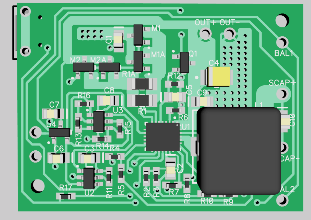

The PCB is 1.188in x 1.625in. It will be fabbed by OSH Park in 2-layer 2 oz. copper and I'll get them around the first week in November. I'm not really happy with the PCB layout -- the NE and NW corners are pretty much empty, so it's not very efficient use of space. But it's 33% smaller than my other circuit so I can't complain too much.
I'll check in again after I get the PDBs and can test it out.
Discussions
Become a Hackaday.io Member
Create an account to leave a comment. Already have an account? Log In.