 Joe Menard
If you are designing anything with a SMPS (Switch Mode Power Supply), battery circuits, solar panel-based power/battery system design, or even linear power supplies, you need to consider how you are going to test that supply/circuit versus desired specifications. A couple years ago I bought a DC Electronic Load to do this testing, and here is why.
For “switchMo” (the new name for this Wall Switch project), the supply design that was chosen is capable of suppling 5VDC at 1A. For the Particle Photon, the desired input voltage range is 3.6-5.5V, and the Photon has its own switcher to get down to 3.3VDC. So, the permissible input range is pretty wide.
The major 5VDC power consumers on the PCB, are the Photon, the relay, and the cap touch switch/display. The Photon is spec’d to require 80-100mA, but in worst case peak burst-mode conditions (heavy Wi-Fi), could draw 430mA. The 5VDC coil relay consumes 450mW, and is spec’d at 91mA coil current. The LED in the cap touch display consumes 20mA when on. So, typical current is 80-210mA (80-100mA plus 90 mA plus 20mA) up to worst case of 540mA.
The equivalent resistance for the peak load at 5VDC (540mA) then is a bit more than 9 ohms, at a power rating of about 2.7 Watts. Nominal power draw would be 1.05 Watts, a nominal load resistance of 25 ohms.
How to test this? You could just use a few power resistors, using a 5 Ohm, 10W model to test 1 amp, and a 10 ohm, 5 Watt resistor for the peak current load of 540mA.
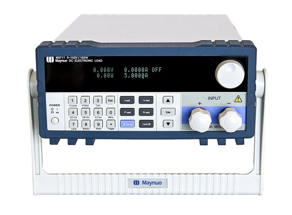
Since I have designed a few SMPS’s, a lithium battery charging circuit, a solar-panel to 5VDC supply and simple linear 78xx supplies, I use a programmable DC electronic load. These can be pricey but the convenience they provide is huge. I bought the Maynuo M9711, on Amazon for $474. It appears to be a clone of a similar B&K instrument ($1195). It works up to 150V, up to 30 amps, at a maximum of 150 watts. It is a static load – you control it manually from the front panel to a specific level.
With this instrument, I could easily and quickly test switchMo’s 5VDC supply. I started at 1000 ohms, dropping down through 500, 100, 50, 25, 15, 10 and finally 5 ohms. The voltage output started at 5.08VDC, and at 5 ohms (almost 1A) had sagged to 4.85VDC. Good enough for the Photon.
Because there is a 560uF electrolytic on switchMo’s 5VDC, it is assumed peak surges from 100mA to 500mA can be met though no calculations were made though. In practice, the Photon worked reliably.
Again, you can cheaply just use power resistors, and this is an instrument I use only a few times a year so is a definitely a bit of a luxury, and a low priority for budget conscious makers (Scope, DMMs and power supplies are way more important). But I found it a great addition to my bench.
Discussions
Become a Hackaday.io Member
Create an account to leave a comment. Already have an account? Log In.