 Stephen Harrison
Design Considerations:
The starting point of this project was the case, I wanted something that a bottle of FormLabs resin could sit on (about 100mm diameter), or be dropped into when not in use to act as both storage and measurement system.
It had to accommodate a load cell and NFC reader to identity of the bottle, ideally be cylindrical to match a bottle. I wanted the bottle to have a NFC label stuck to the underneath, that makes it easy to align the tag with the reader, without having to rotate the bottle to align the tag.
The case also needs to support either a battery or a power connection of some kind.
The initial designed idea allowed for a NeoPixel ring to be embedded in the top half to show the user a clock style usage gauge however these are power hungry and blocked when the bottle is on the scales, so these have not been use further.
The scales are internet connected and no interaction is needed for normal operation other than placing the bottle on them and removing at an appropriate time. The user does not need to know the measured weight so no display is needed and only a single LED and buzzer are used to give feedback which greatly simplifies the case design.
The final design consideration was to make it drip proof. The top should either be a solid print or support a coating of epoxy to seal in any electronics, mounting hardware and anything else.
The load cell was easy, the type found on eBay rated at 5Kg are smaller than the bottle diameter so would fit without too many problems. The NFC readers on the other hand were more problematic. Their are a number on the market similar in design to the AdaFruit PN532 NFC Controller breakout board where the aerial is an extension of the PCB. To use these we would need to extend the top case to accommodate an oversized PCB sticking out the back, this starts to make the design look ugly and clumsy as well as difficult to seal.
Initially I tried the RC522 type readers from eBay, however these don't appear to support the NFC tag type (NTAG2) that is used by the stick on NFC tags (or at-least the ones I was able to buy easily). Fortunately I found that the PN532 NFC readers sold on eBay were a perfect size (less than 45mm x 45mm) so they would fit nicely underneath a bottle and they are also able to read the NTAG2 tags. As an added bonus they use the same controller as the AdaFruit board so I was able to use the driver developed by AdaFruit. More on the NFC side of things later.
Battery wise I planned on using a 3000mAh LiPol cell that comes with the Particle Photon power module and the Electron as I have a few of these to hand, again this would fit nicely to one side of the load cell within a diameter that worked for the bottle.
With the NFC board being smaller than the diameter of the design it would be easy to finish the print with a coat of epoxy resin to provide a drip proof top case.
Design Software:
Being a programmer I use OpenSCAD for most of my 3D designs, generally it works well for simple designs like this one and allows for parametric designs. OpenSCAD is open source, licensed under GPL 2.0.
The stl files are provided and are directly printable by most 3D printers so you don't need OpenSCAD to make the case.
Case Design:
Initially I went with a cylindrical design with a square section on the bottom half sticking out backwards to house the electronics. However as with nearly every design things change as you try them out and either don't work or present nicer ways to achieve the end result.
With the initial design it required 7 wires for the NFC reader and another 4 for the load cell, this very quickly got messy when trying to assemble the scales and was noticeable that those cables would exert strain on the upper half that may effect reliable measurements, additionally with the load cell and NFC being permanently connected to the top half, it made opening the case troublesome and risks the connections of the delicate load cell wires.
Typically when designing a 3D printed case you will look to have the two halves joining snugly, however the nature of the load cell is that it flexes very slightly with load being placed on it, likewise there will also be a small amount of movement with the 3D printed case so the design needed to allow space between the top and bottom to prevent these two contacting and effecting the measured weight.
I also wanted to protect the bottom half of the case with electronics inside it from drips of liquid when the bottles were being weight, so I elected for a skirt on the top half of the case, this fans outwards from the top and has a good clearance around the bottom half. Any drips from the bottle will flow down the skirt and onto the bench below.
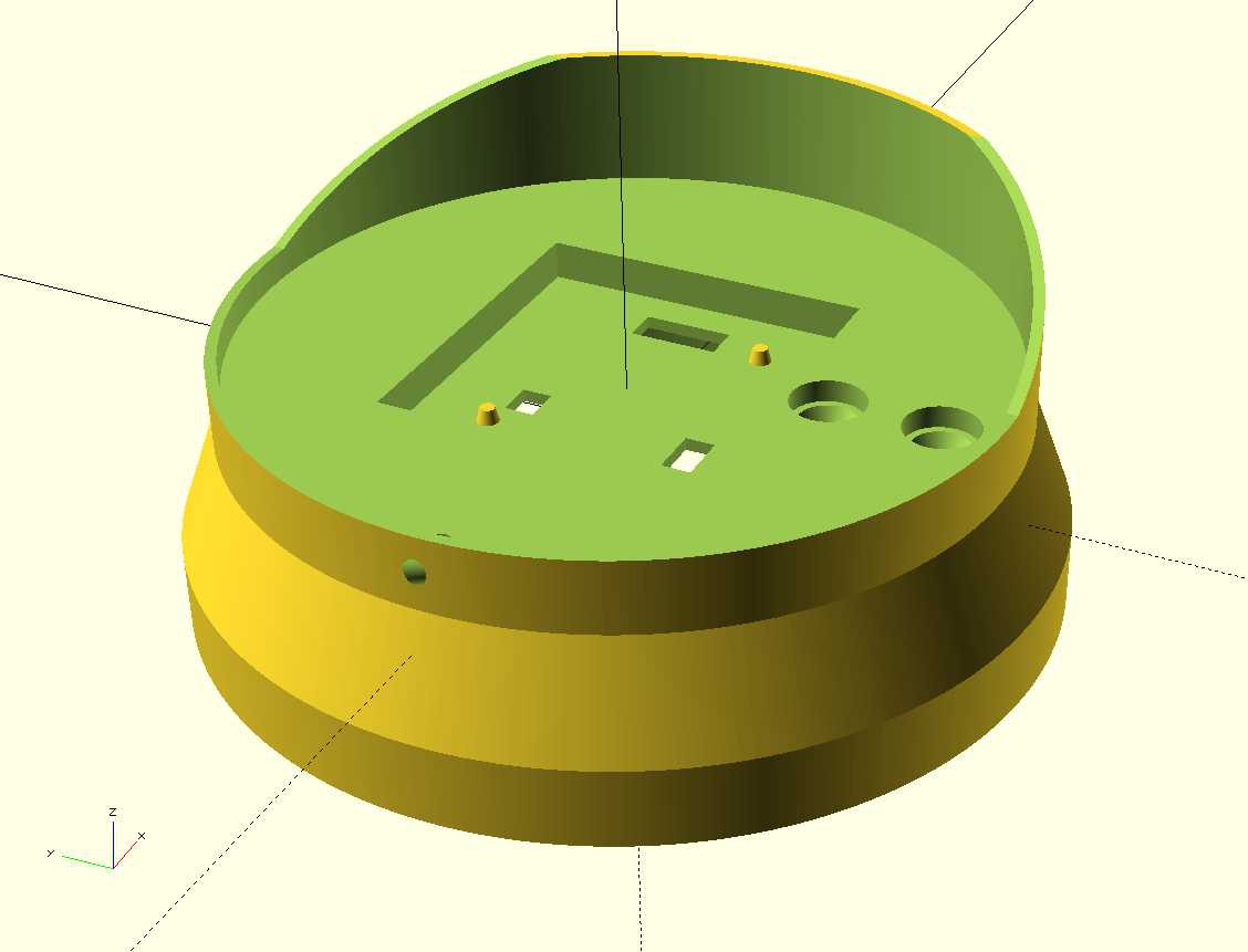
Trying to create a skirt that went around a half square and half round base and looked nice didn't work so well which re-enforced the idea of a purely cylindrical design, this combined with the wiring issues pushed me down the route of a custom PCB that would allow the electronics to be mounted in the top half of the case, the NFC reader could then be connected by pins through the print to the PCB. The load cell would be mounted by 2 M4 machine screws to the top half, these are then covered in epoxy resin so the load cell is permanently attached to the top half. The PCB design was simple at this stage as a prof of concept and sent of for fabrication.
The PCB and electronics will be details in another log, but for now the design was a circular PCB just smaller than the diameter of the scales with a cutout for the load cell in the middle. Initially the load cell amplified PCB was still separate but it included the micro-controller (a Particle Photon), power input, connections for a possible NeoPixel ring, 4 pins for the NFC I2C and Power, the others are done by flying wires onto test pads to make alignment easier.
The top case then needed pads on the underneath to support the PCB.
The top side of the top half is designed with a cutout for the NFC PCB with 3 openings to the underside to connect to the PCB, two recessed M4 countersunk screws for the load cell, a border around the outside to allow this area to be filled with epoxy to make a nice level drip proof top, and then a raised back (or an all round cylinder) to finish it off nicely and help with bottle placement.
Whilst it would be possible to alter the design to print the top half up-side-down to give a nice finish on the top surface it would mean that we would have no lip for the epoxy poor and no back to the design, or we would end up with support material markings on the top surface which would look ugly in the most noticeable place.
Printing the top the correct way up means we need a lot of support material to fill the inside of the skirt until we get to the main body, however all of this will be hidden from sight and with a little clean-up doesn't effect the part, but it does waste a lot of filament and time.
For prototype designs or where most of the system is not visible it is possible to print without the skirt which drastically decreases the print time and makes it easier to get test wires in and out of the system.
Top Half:
The file BottleBuddyTop.scad is the design for the upper half, the design can be customized with the following settings:
* bottleDiameter: Default of 100 (mm). This can be increased for larger bottles. However care should be taken not to make it too large as the forces on the load cell connection may make it wobbly or fragile. Also the LED alignment hole with the PCB will start to be in the wrong place.
* sliceTop: Default true. This creates the slice through the top of the cylinder that extends upwards and creates the small back raised section. With the is set to false a full (hollow) cylinder is used to contain the bottle which might be preferable if used as storage for the bottle as well.
* epoxyDepth: Default 4 (mm). This governs how deep the outer ridge is on the top to allow an epoxy coating to be poured on.
* skirtOption: Default 2. This generates version 2 of the skirt (a cylindrical skirt). Set this to 0 for no skirt for a quicker print, or 3 for a polygon style skirt. Version 1 no longer exists.
If you make changes, use OpenSCAD's Render option to create a full render and then export as .stl
Print using Cura:
I use most of the default options for Fast or Normal print with infill increased and support enabled.
- Layer Height: 0.15mm or 0.1mm
- Wall Thickness: 1.05mm
- Top/Bottom Thickness: 0.8mm
- Infill Density: 40%
- Print Speed 60mm/s
- Support: Enabled
- Build Plate Adhesion: Skirt
Bottom Half:
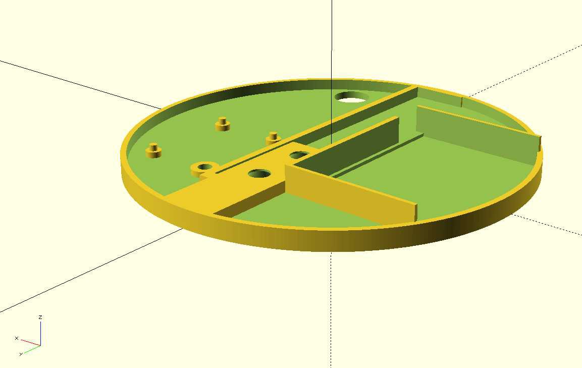
This is still work in progress and includes a mounting point for the load cell amplified PCB that will be removed with the next version of the main PCB, it also includes a battery compartment that is also unfinished.
Underneath it has 4 slightly raised sections for rubber feet to be attached, slightly recessed countersunk holes for M5 screws for the load cell and a hole for the power cable to exit (again a temporary measure for testing).
The file BottleBuddyBottom.scad is the design for the lower half, the design can be customized with the following settings:
wallHeight: Default 5 (mm). This is how height the outer wall is, it only needs to be tall enough to sit inside the top half skirt to hide the contents.
bottleDiameter: Default 100 (mm): Same option as is used for the top half. If you need a slightly larger design increase this. The load cell placement will not move so it will still align with the top half.
Print using Cura:
Again, I use most of the default options for Fast or Normal print with infill increased but support disabled for this half.
- Layer Height: 0.15mm or 0.1mm
- Wall Thickness: 1.05mm
- Top/Bottom Thickness: 0.8mm
- Infill Density: 40%
- Print Speed 60mm/s
- Support: Disabled
- Build Plate Adhesion: Skirt (You may prefer Brim if you get warping)
Discussions
Become a Hackaday.io Member
Create an account to leave a comment. Already have an account? Log In.