0%
0%
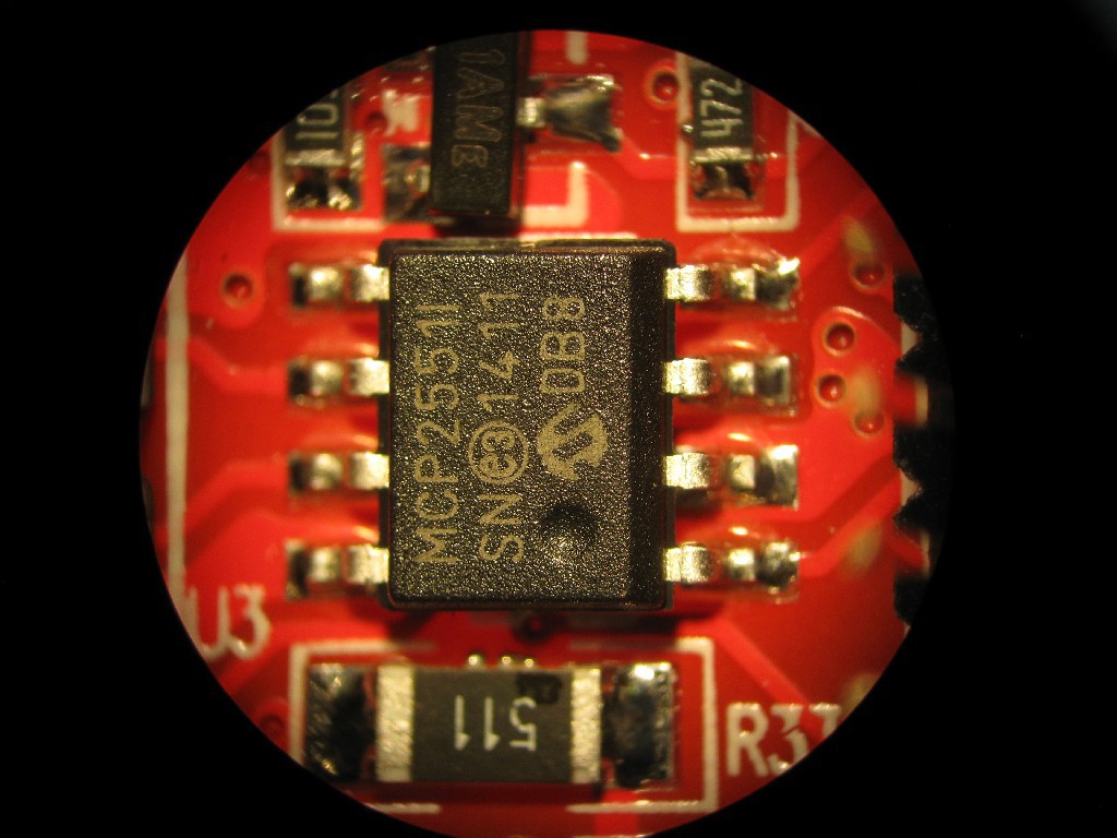
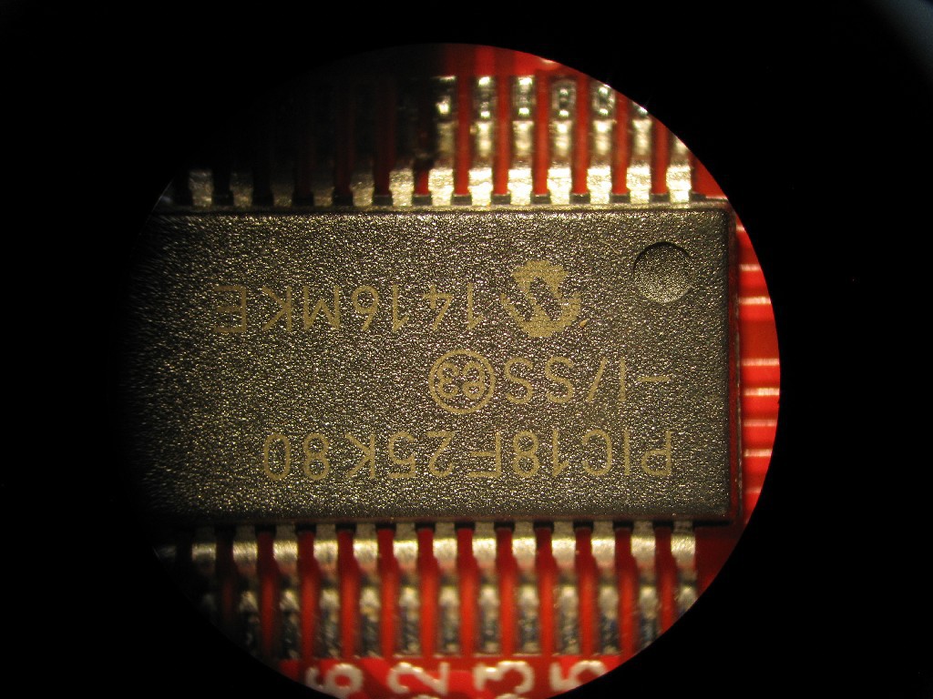
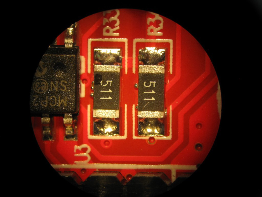
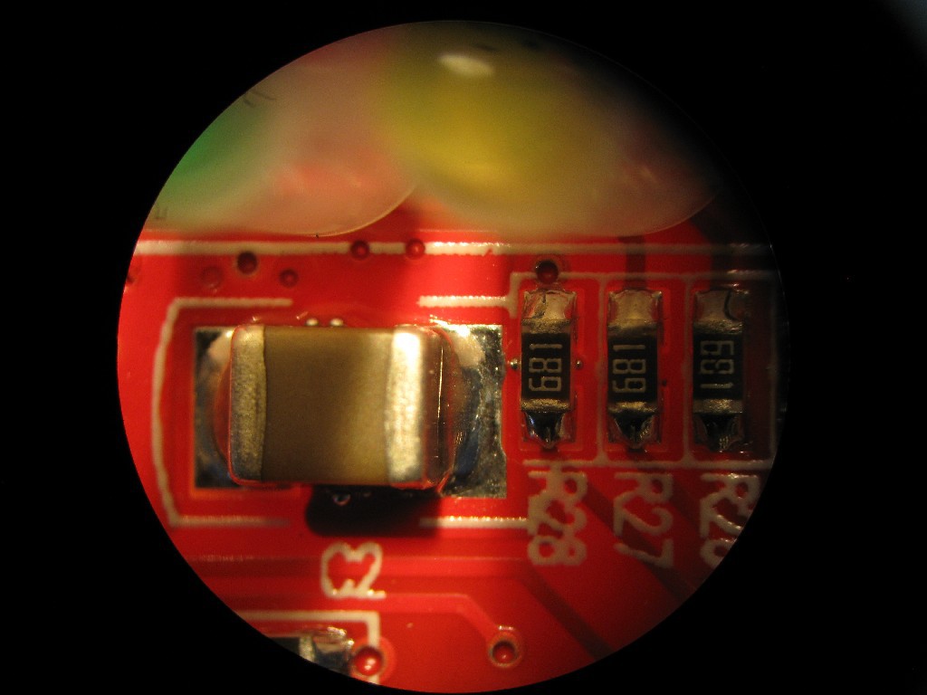
DBPOWER ELM327 Wi-Fi Interface (OBD II) "review"
just out of interest I bought one of these to play with
 rawe
raweBecome a Hackaday.io member
Already have an account? Log in.
Just one more thing
To make the experience fit your profile, pick a username and tell us what interests you.
Pick an awesome username
hackaday.io/
Your profile's URL: hackaday.io/username. Max 25 alphanumeric characters.
Pick a few interests
Projects that share your interests
People that share your interests


 h4rdc0der
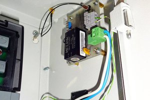
 Ruslan
 Blecky
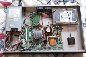
 Remi Serriere
Hi Rawe great info>
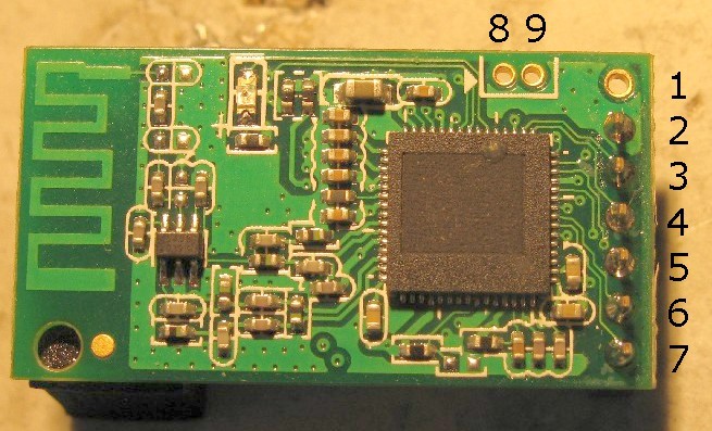
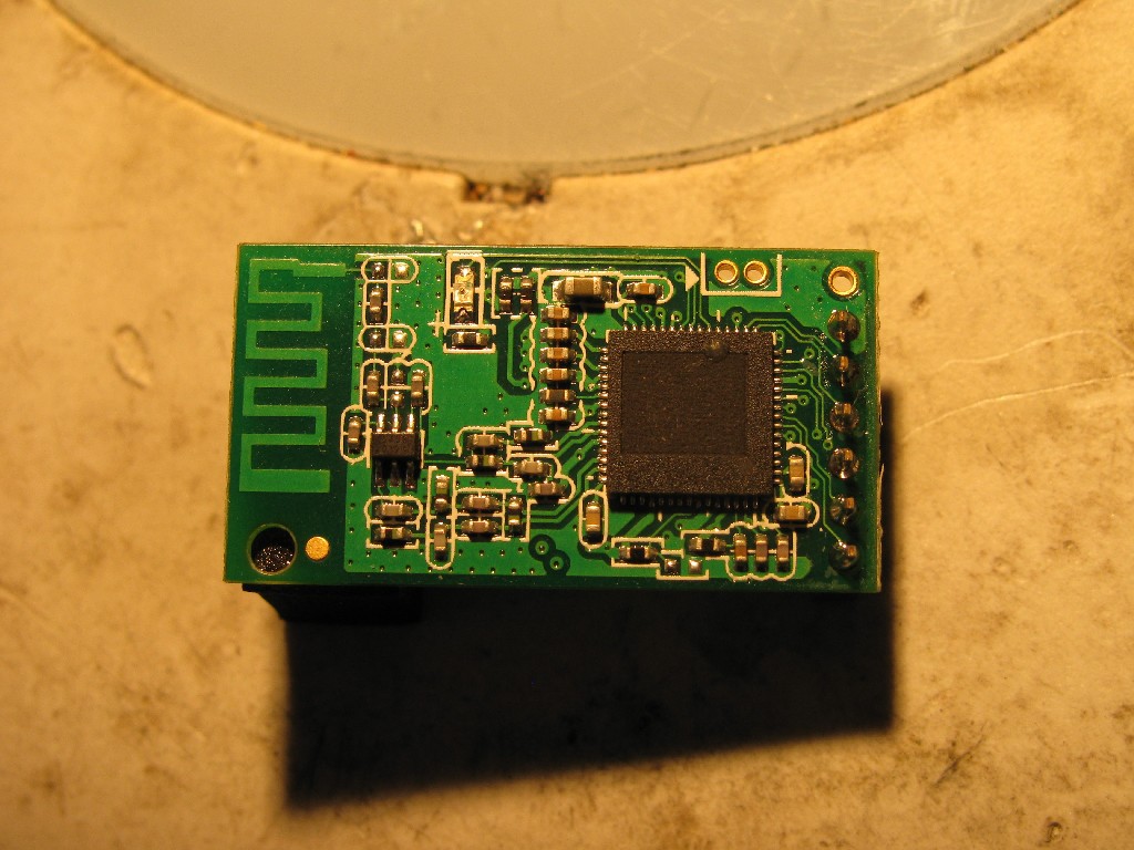
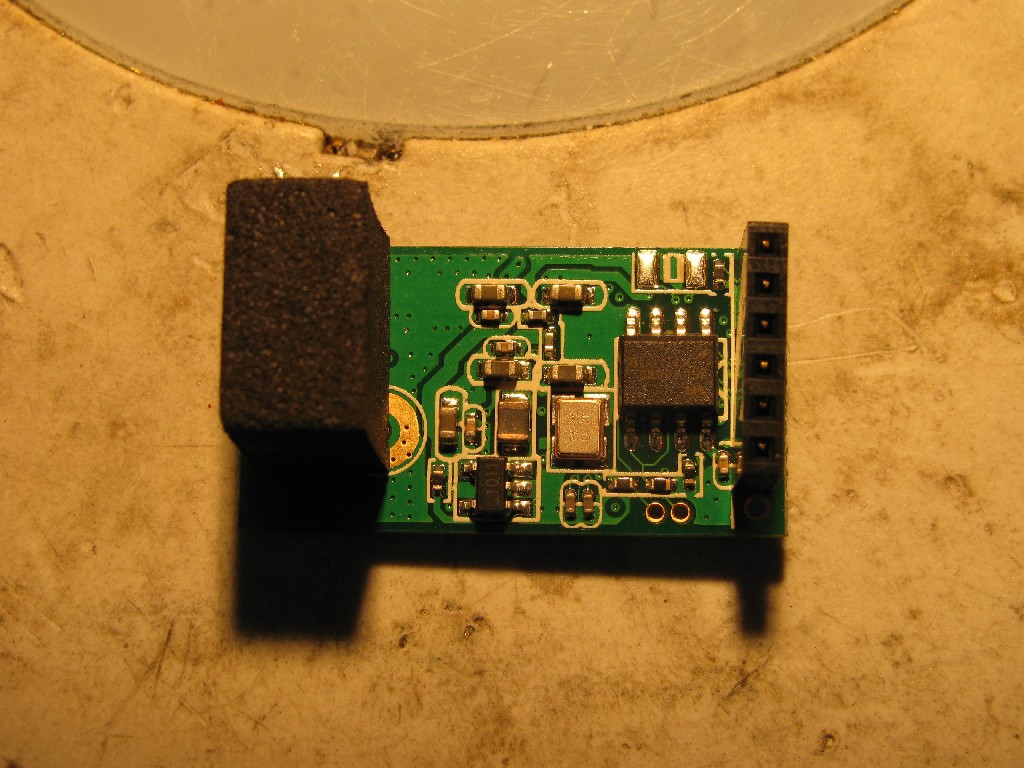
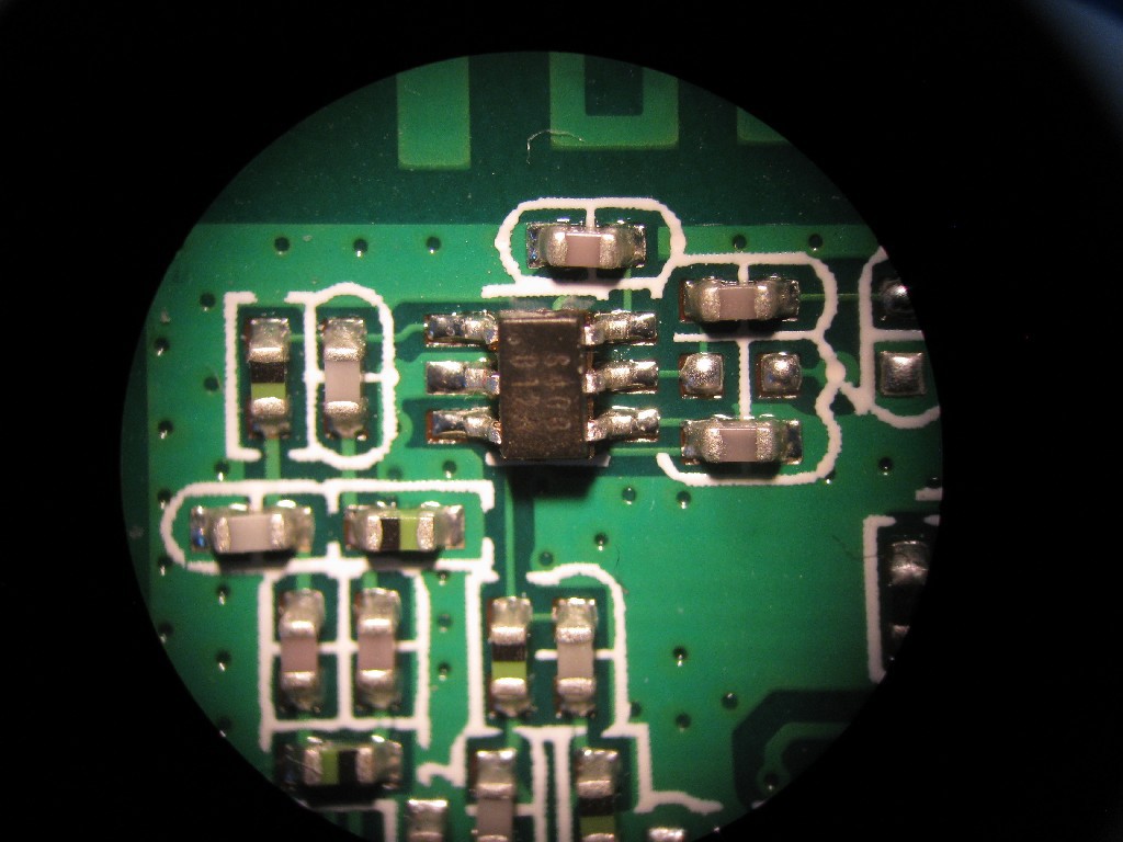
I put mine AP mode it got stuck at HEX 10 digit password instead of ASCII WPA2PSK which the AP kicks it off i tried hours and different combination i came to the conclusion that I need a serial header connection or some sort of factory reset of the WiFi chip< is there anything I can do? its the older version with the PCB separate from the WiFi module .
I tried shorting GND to RST on the WiFi module UARTO , for 30 seconds, and 30 seconds while powering it up.
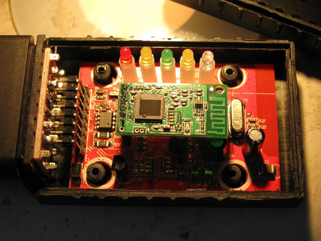
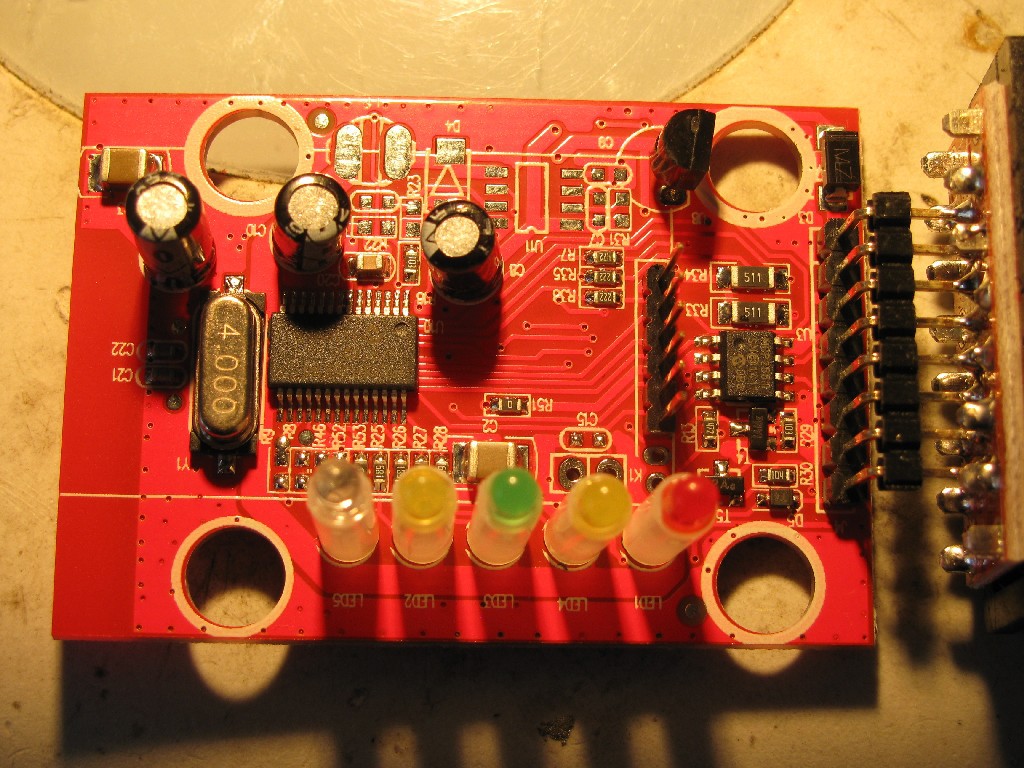
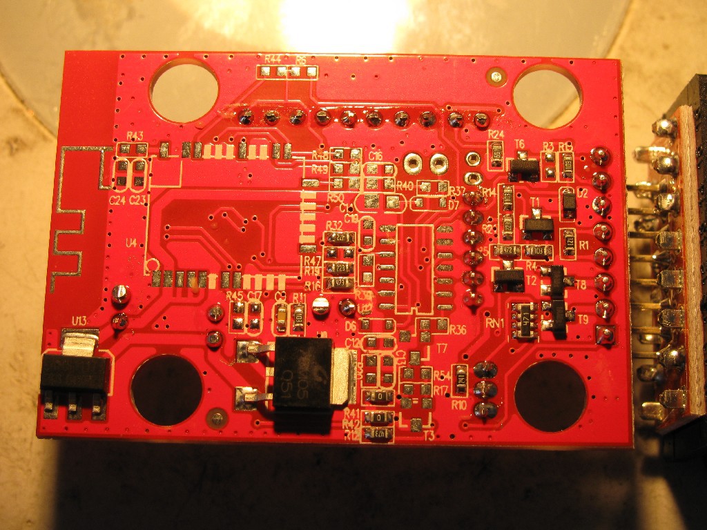
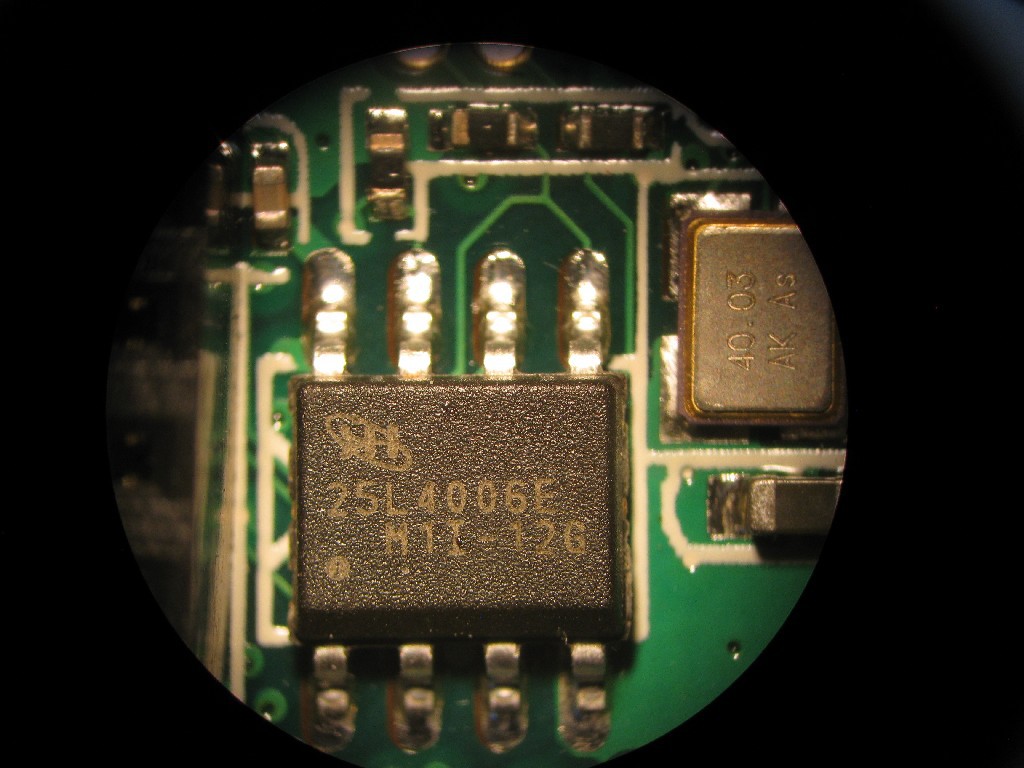
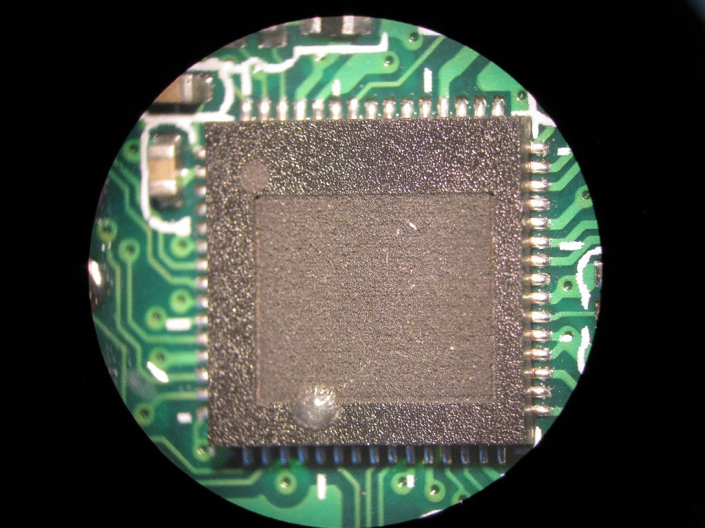
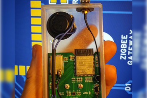
here are more pictures of the unit
https://forum.allaboutcircuits.com/threads/how-do-i-reset-this-wi-fi-pcb-module.177225/