 polyfractal
Did you see this update coming? I did. Nothing ever works r̶i̶g̶h̶t̶ ̶t̶h̶e̶ ̶f̶i̶r̶s̶t̶ ̶t̶i̶m̶e̶ ever. :)
The Good
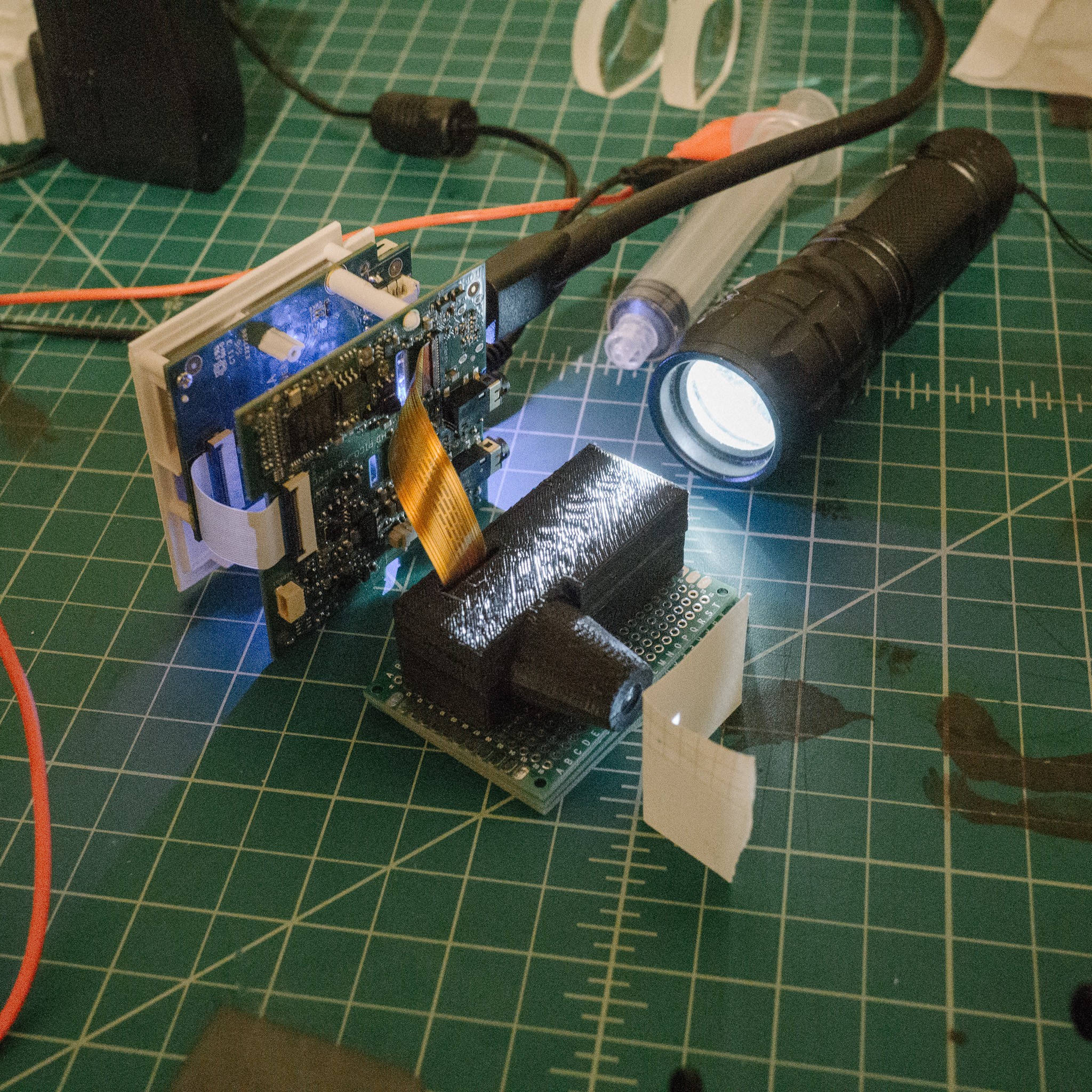
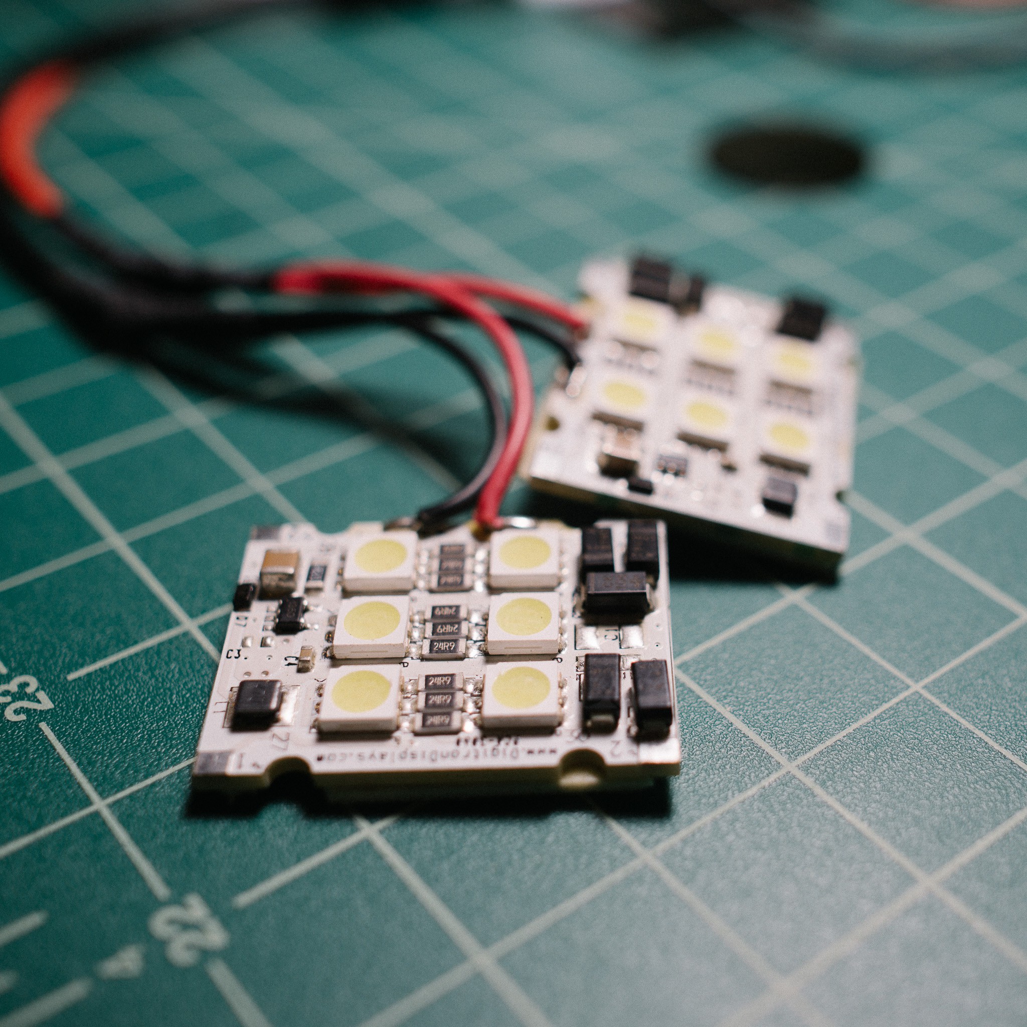
So good news first. Generally, roughly, mostly, the optical enclosure works. It assembles well, the components are held firmly and generally in the correct position, etc. And most importantly, the LCoS didn't die during the disassembly and we can still project an image.
Using white light, we can display a test subject on a piece of paper. It even looks pretty good (apologies for the angle/distortion/focus, it was really hard to photograph this):
The Bad
Ok, time for the list of things that went wrong :) The first and most obvious issue is that not quite everything was aligned correctly. And there were several occlusions in the light path (usually the corner of a component holder slot).
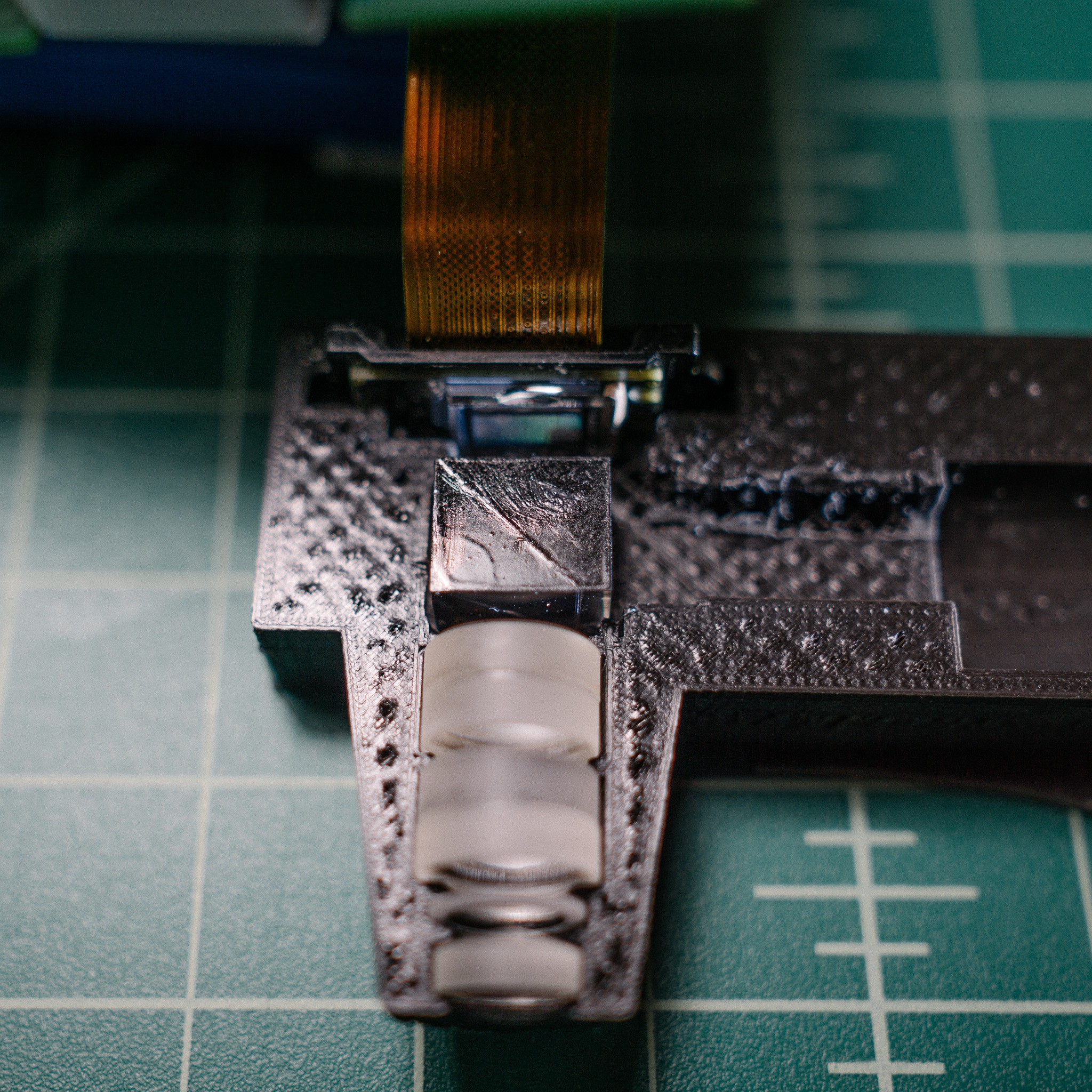
The worst, unfortunately, was the beam splitter. If you look at the photo above, you can see a smear of diffuse white light to the left of the test image. That's caused by misalignment of the splitter.
It took me ages to figure out why though. The cube looked well centered and aligned, but was obviously the culprit. Eventually I noticed the problem. Can you spot it?
Here are some annotations to help:
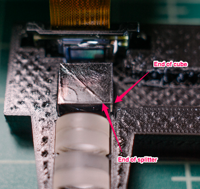
Yepppp... the splitter is not centered within the cube. Or rather, the cube is not a cube, it's a rectangular solid. The splitter cuts across at a 45° angle, but the whole prism extends a bit further. Why? I have no idea. Maybe it provides an easy place to anchor the PBS to the assembly.
Whatever the reason, it totally screwed up my alignment. I did some field surgery on the printed assembly (yay PLA) and manually centered the PBS, which helped considerably.
Phew! Problems solved!
Bad news, Part II
Hah, yeah, not quite. Once I had the components working relatively well with white light (because it is easy to manually confirm focus), I moved on to the 405nm laser light.
Which did not work at all.
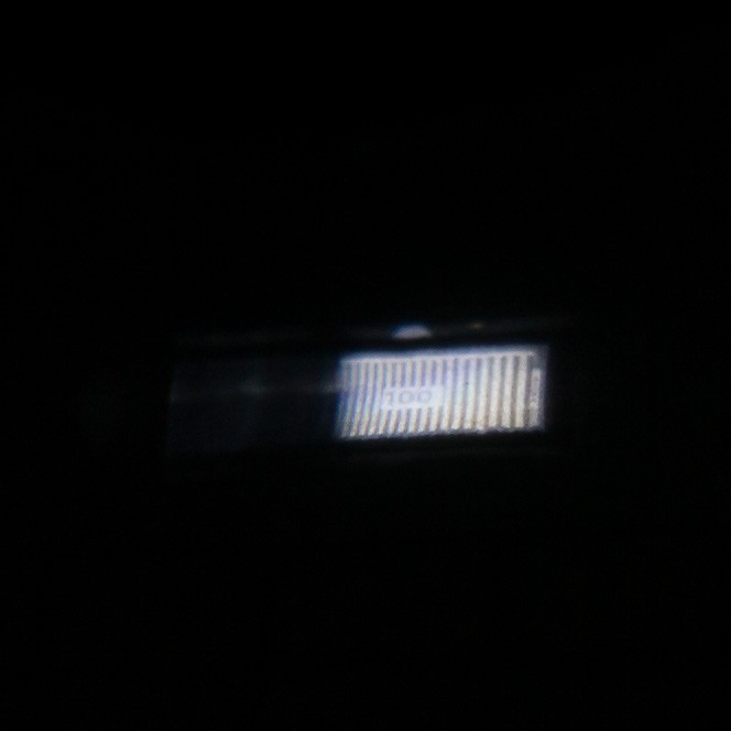
Here is a projection of the same test pattern. I pulled the paper away a bit to enlarge the projection so it would be easier to see (annotated to help identify the test pattern):
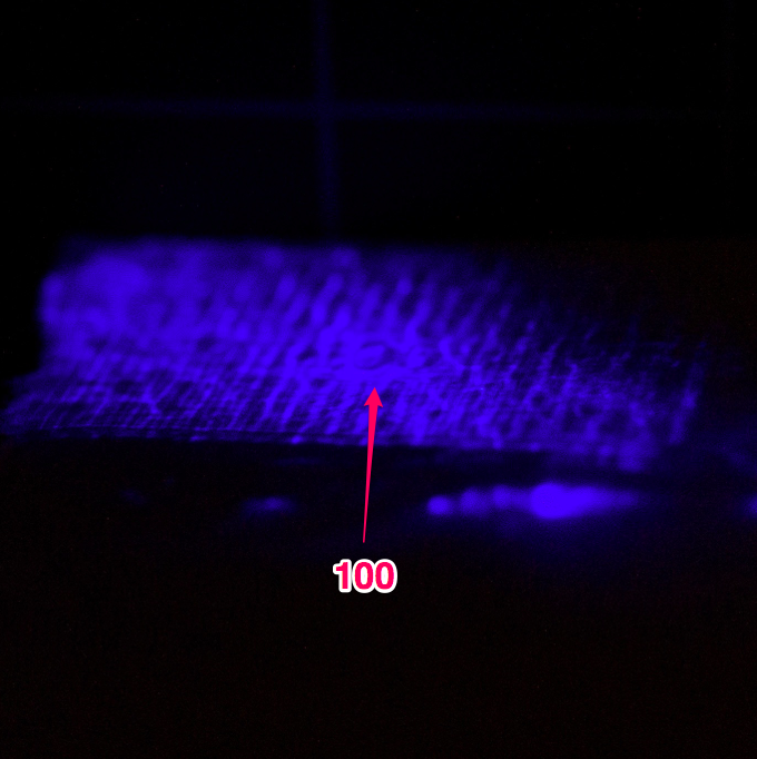
Frankly, I really don't know. But I do have some guesses:
- The polarized beam splitter is not rated for near-UV light. While technically still in the visible range (400+), it's pretty deep-visible. Perhaps the polarizer just doesn't work with these wavelengths. If you look closely at the "mirrored" section of the splitter, you can see a wavy texture that is similar to the noise in that above image
- Something is amiss with polarization states. Since the splitter relies on S and P linear polarization states to work correctly, it's possible my laser is not playing nicely. I did try to rotate the laser to see if that would help (e.g. maybe it was emitting S when I needed P, so rotating 90° would fix that) but to no avail. So perhaps my laser is emitting circularly polarized light?
- Interference patterns of some sort. Maybe the light is interfering with itself somewhere in the light path (similar to an interferometer) and causing those standing wave patterns?
I honestly don't know. The plot is made thicker because I discovered the plastic "reflector" from last post is, in fact, a polarizer. Rotating it in front of the laser goes from 100% to 0% transmission. The "quarter-wave plate" seems to have no effect whatsoever. So who knows.
I'll keep fiddling with the laser as time permits, but I think I'm going to go for a brute force solution for now:
Discussions
Become a Hackaday.io Member
Create an account to leave a comment. Already have an account? Log In.
Your project is amazing! I've just bought exactly the same pico projector for a lcos hack after seeing your teardown. May I know how you feed the image to LCoS after the disassembling? (see the picture in "the good" section) Because i am afraid that the image may be totally un-recognizable when light engine is disassembled. Thank you very much!!
Are you sure? yes | no