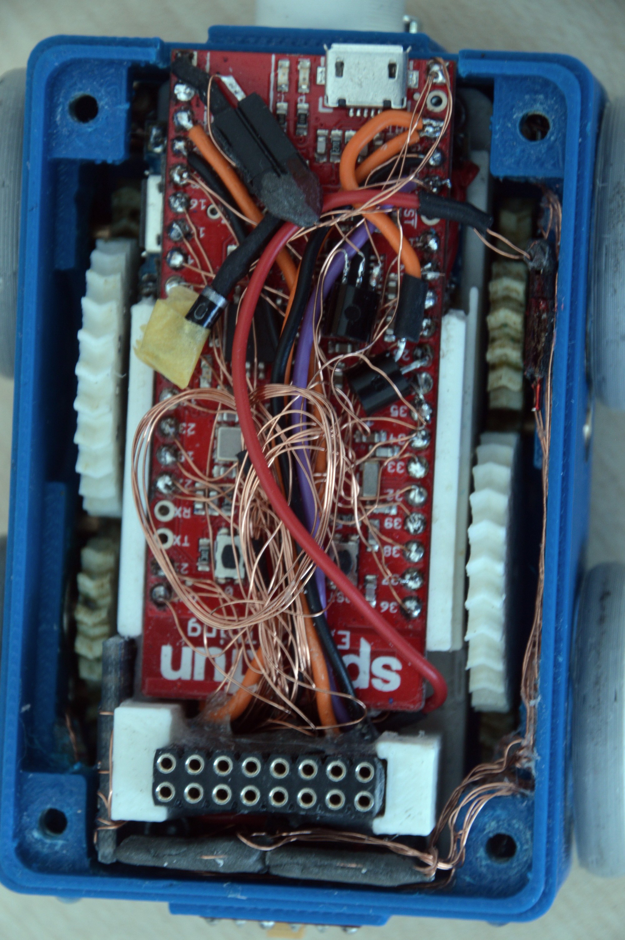
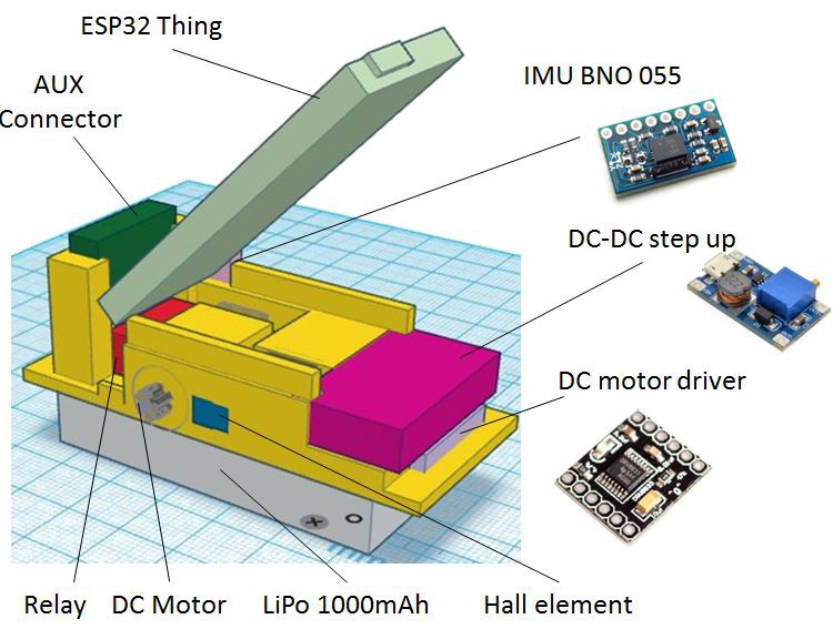
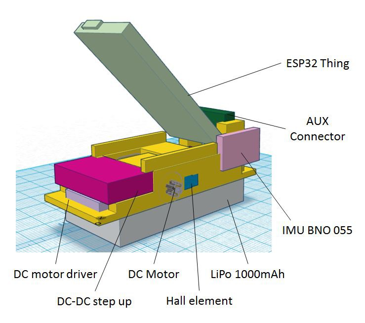
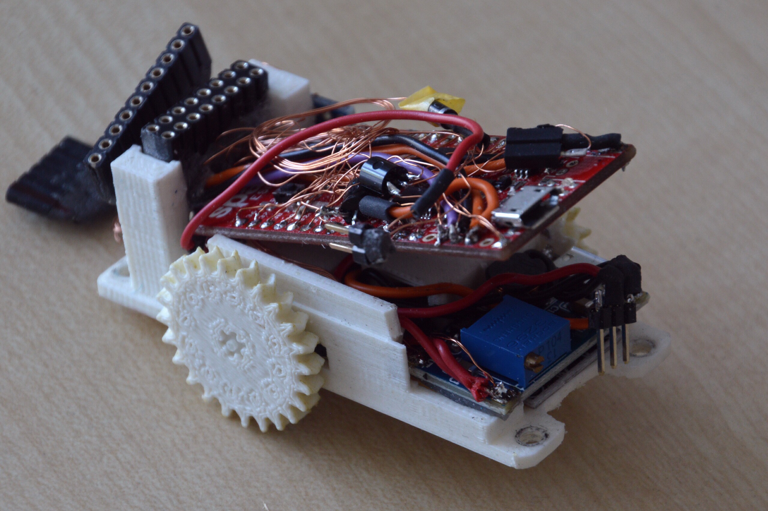
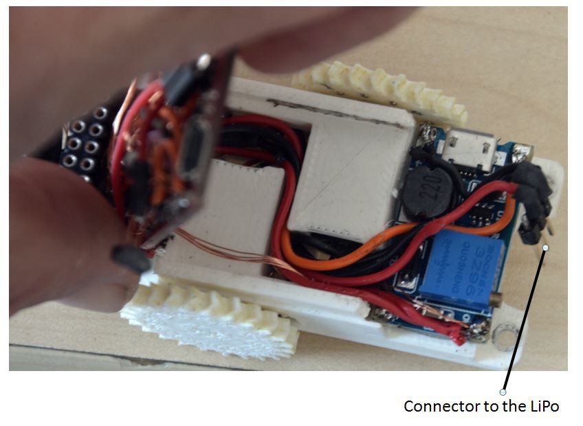
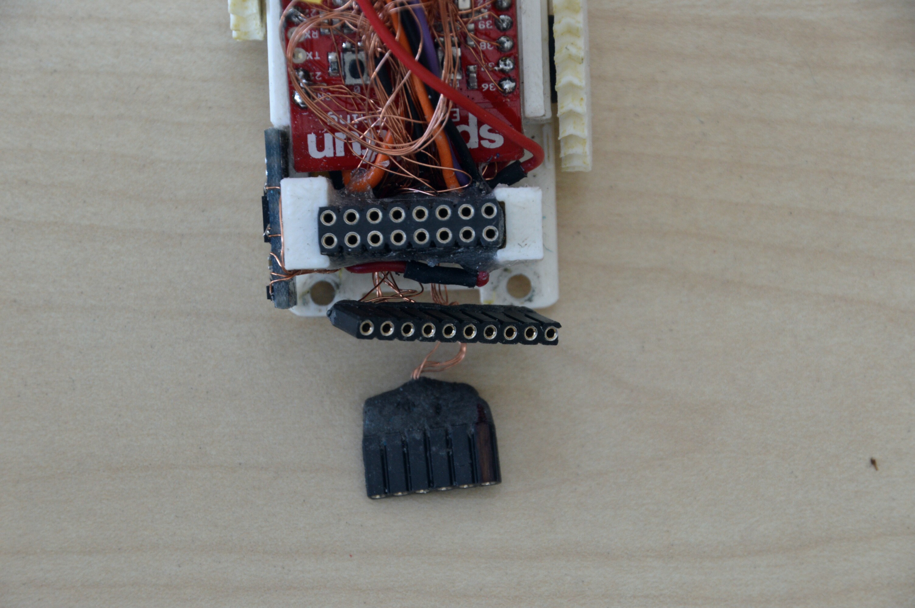
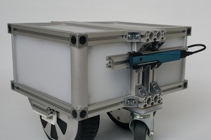
The general idea is a LiPo battery on which a driver & a controller module sits, this includes all basic internal sensors. It is screwed into a housing which hosts the sensors needs to “see the surroundings” (proximity) and hold the wheels. On the front, the rear and top are electrical connections and nuts to attach further sensors or actors. Between controller module and housing all connections are plugged which allows the robot to disassemble if it is required.
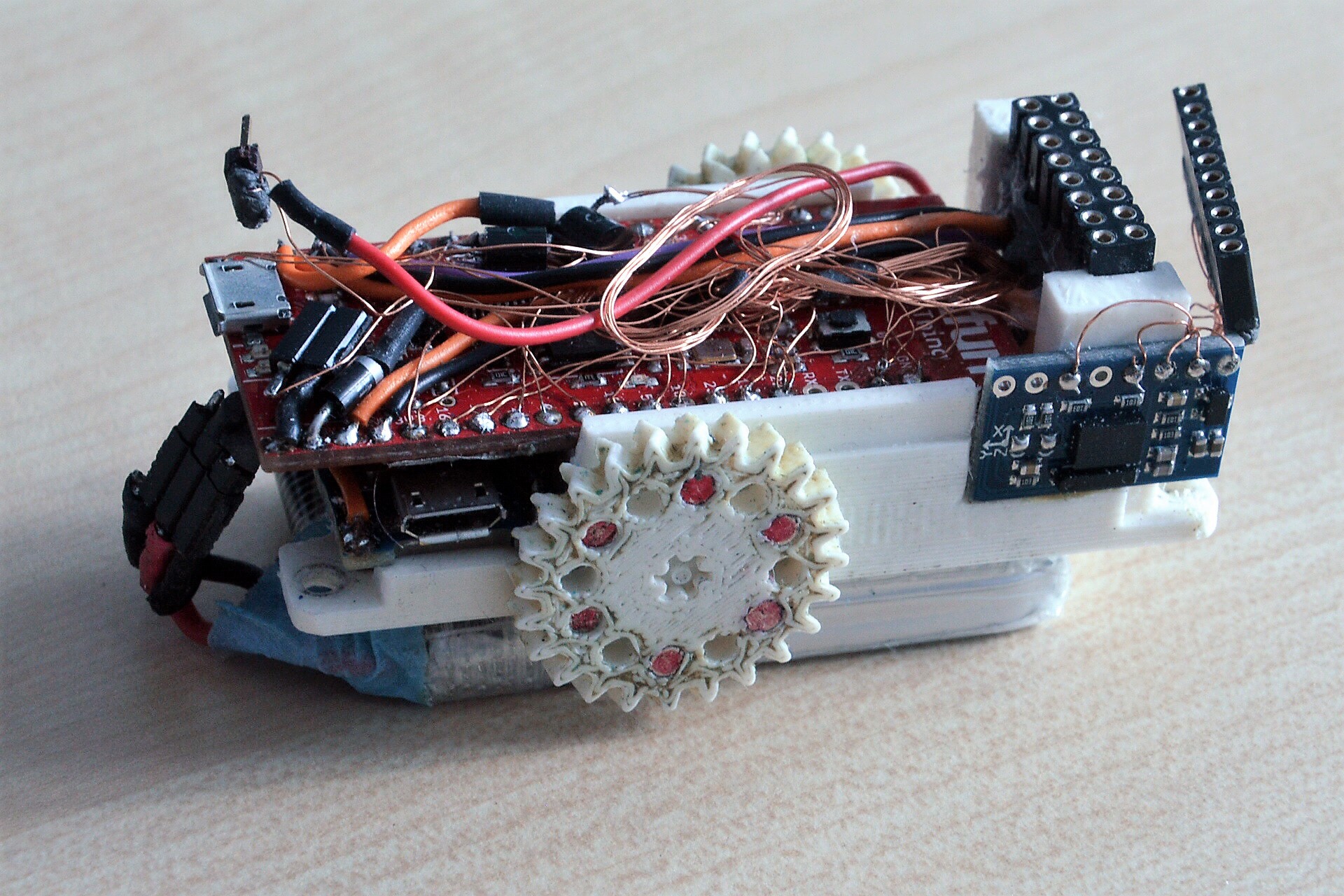
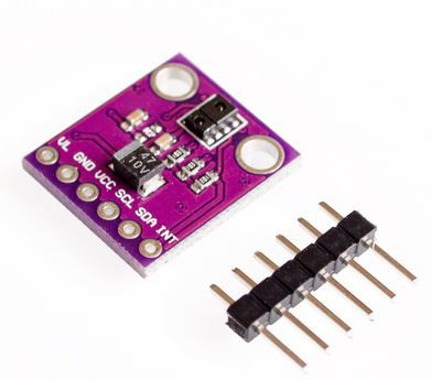
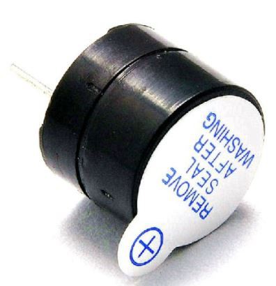
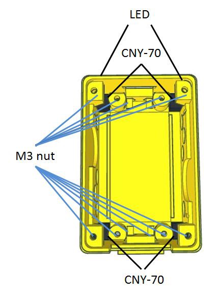
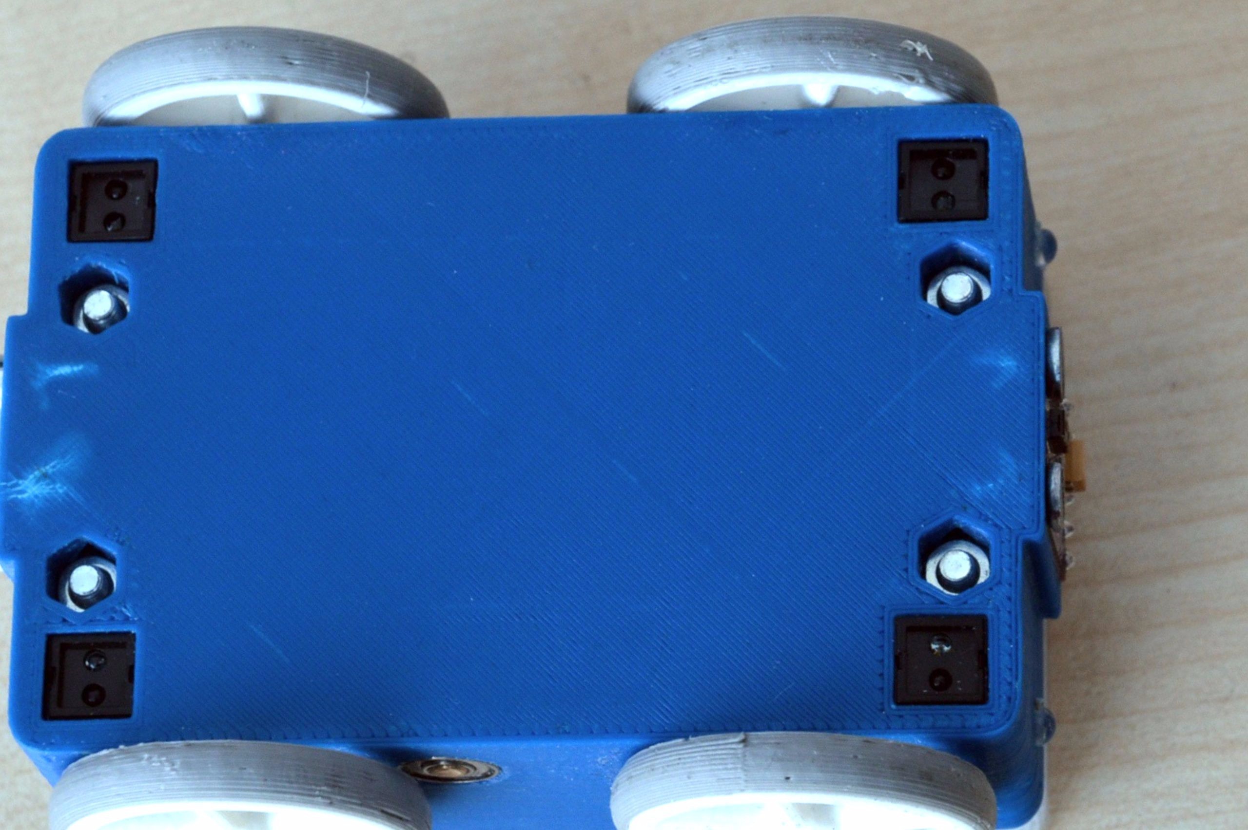
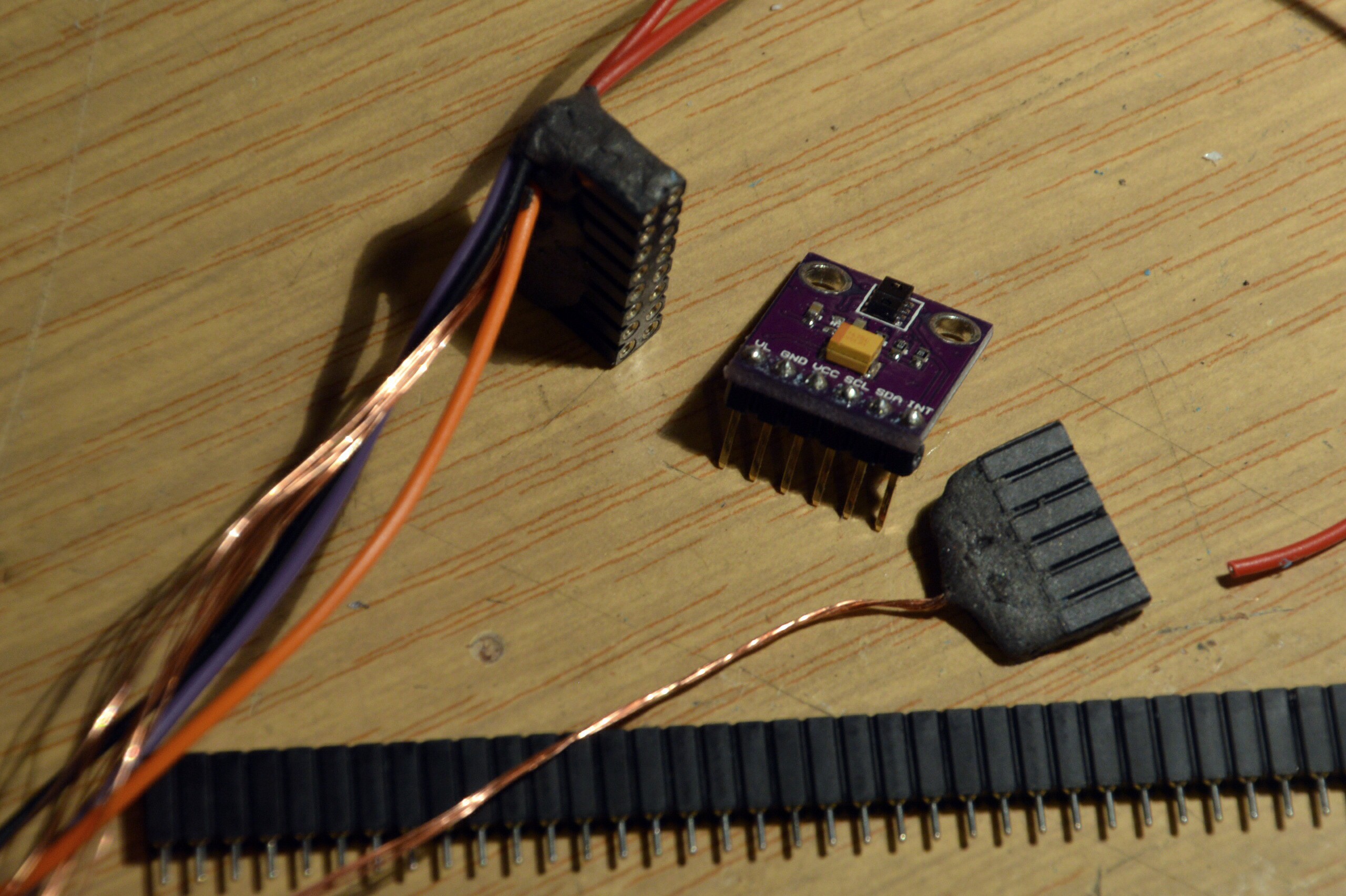
As controller board an ESP32 Thing board is used this can be programmed by the Arduino IDE and allows even OTA updates. It isn’t the cheapest but offers a compact size and includes a LiPo charging capability (Which I managed to blow off by attaching the LiPo in reverse polarity L). As sensors the robot contain a BN0 055 absolute orientation sensor, a rotation encoder for both sides, four proximity sensors in the bottom (line follower, gap detection) and an APDS-9930 proximity sensor in the front to “see” obstacles. Of course a beeper and 2 head light LED’s are not missed either.
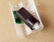
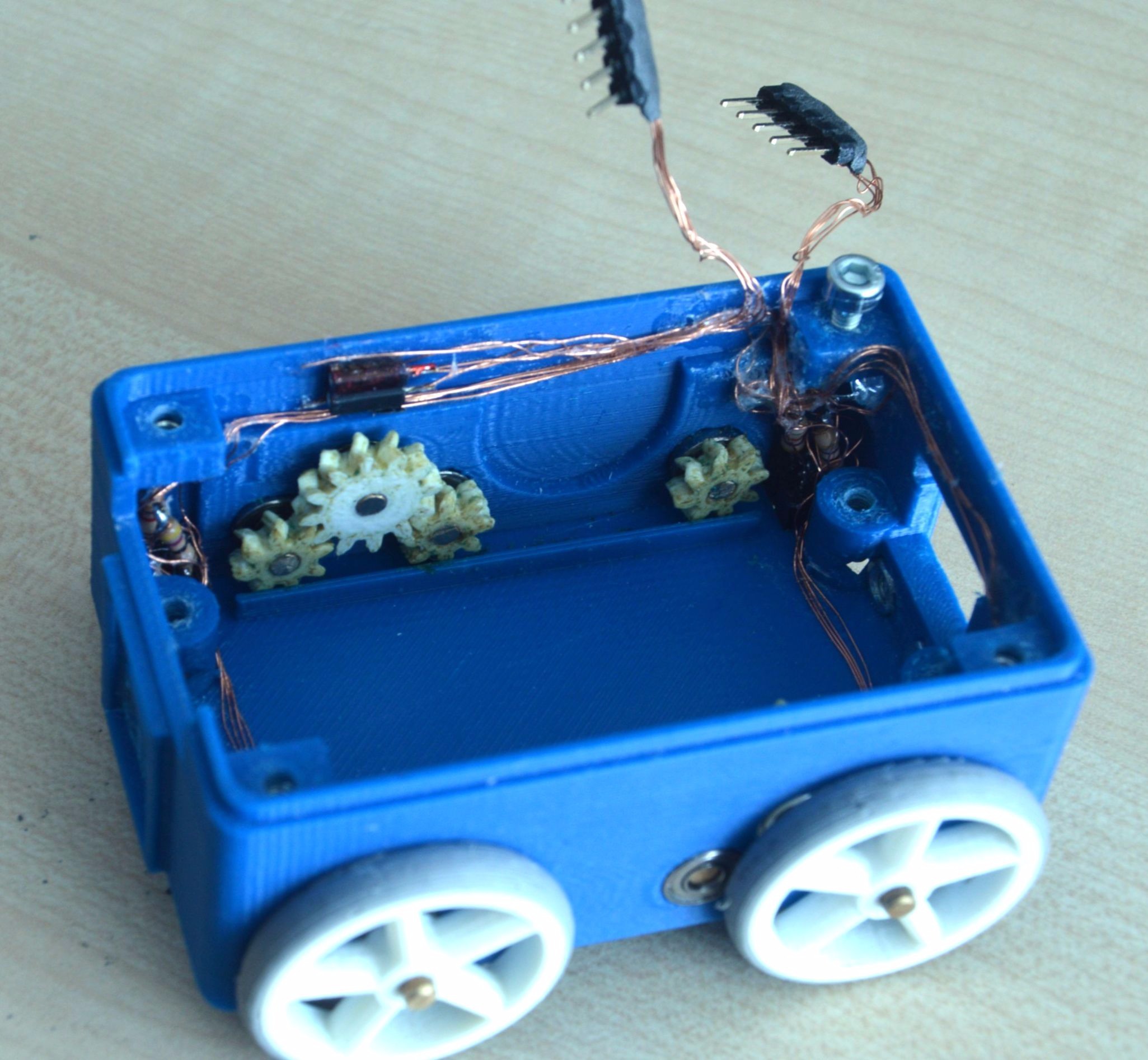
As engines two 714 hollow cup coreless motors with a planetary gear are deployed. With a diameter of 10mm and a length of about 21mm they are small but pretty powerful. They do @ 6V about 300 RMP and provide with a 3:1 transition a reasonable speed to the robot. As the LiPo provides only 3.7V a DC-DC step up converter is also part of the robot in order to enable the motors for its full power.


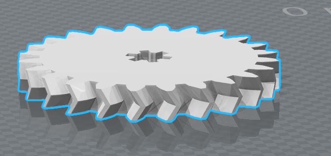
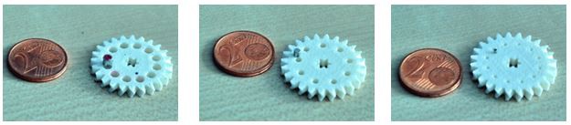
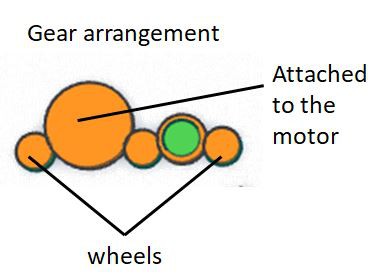 A 3mm brass rod can be used for this and will stick well in to the gears. The axle length for the 12 teeth and 2 of the 8 teeth gears is about 10mm while other 4 axles (were the wheels are placed) needs to be about 18mm in length.
 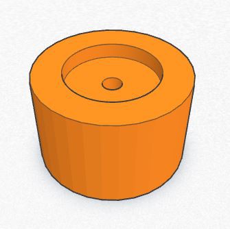 As mentioned the dimensions allows just pressing them into the gears and wheels without any further fixations. But as it’s possible to press them under an angle into the wheels a simple gauge should be used.
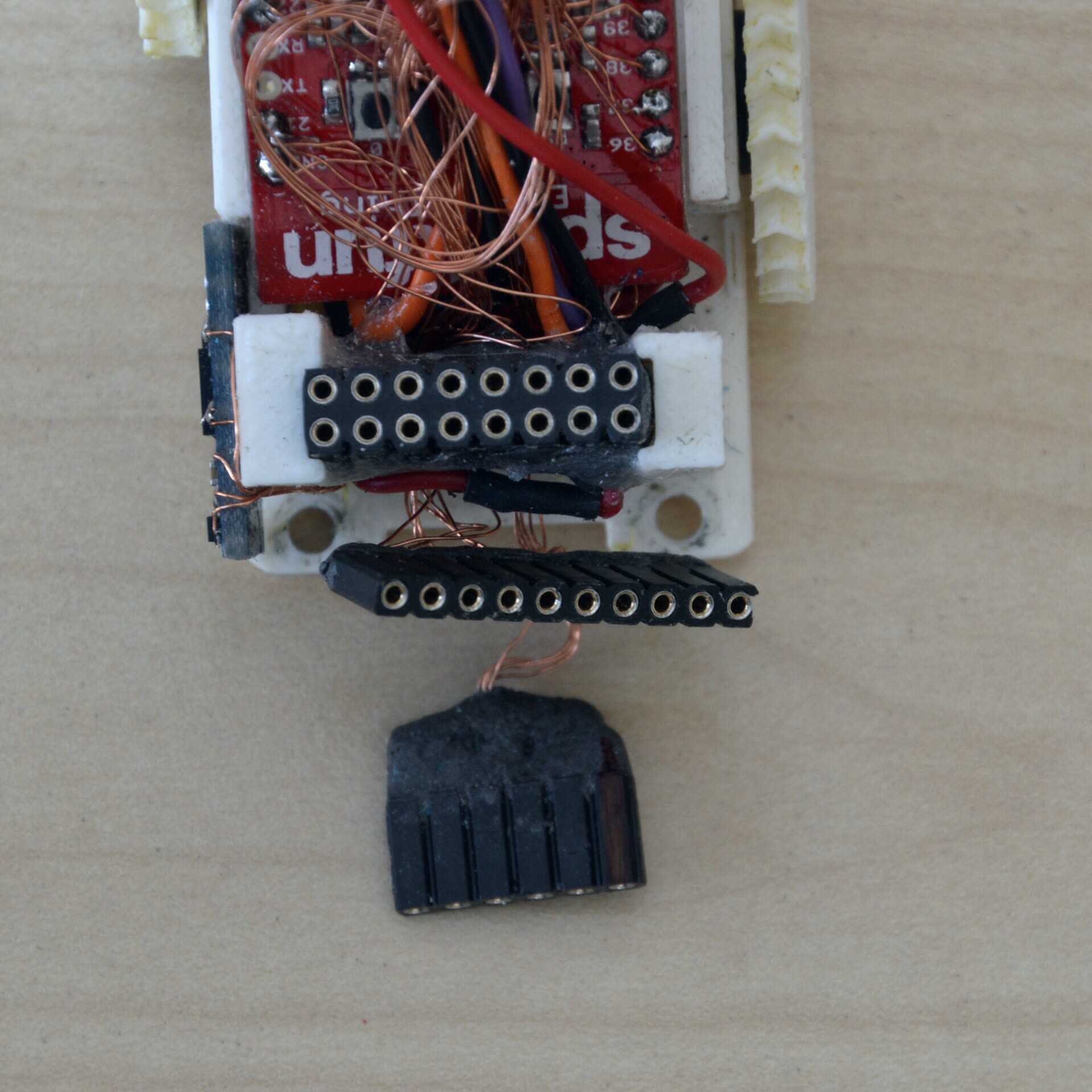

 Roald Lemmens
 Mike Rigsby
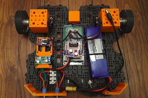
 matop
matop
 NotBlackMagic
where did you buy the motors?