 Evan Stanford
How it works
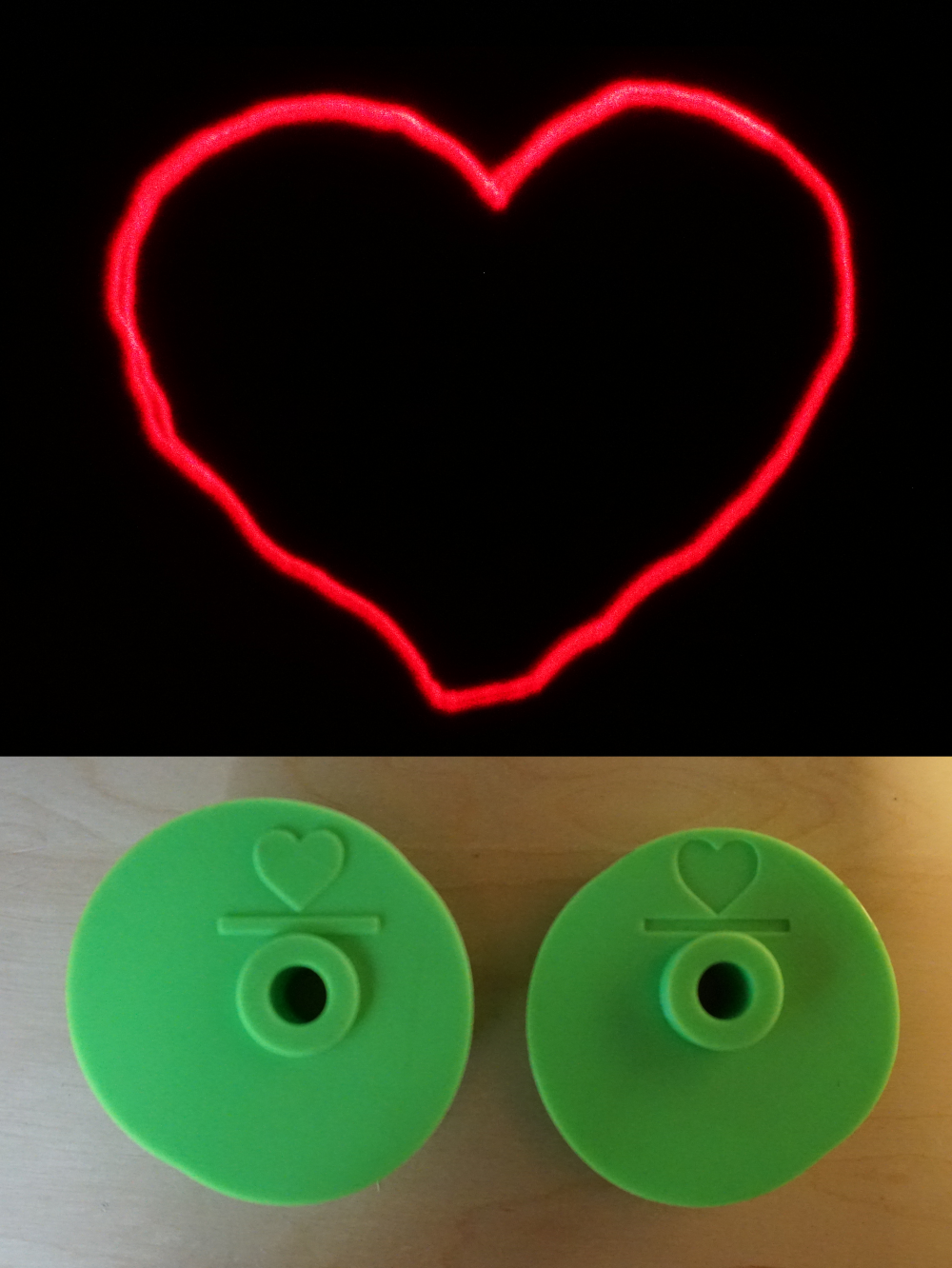
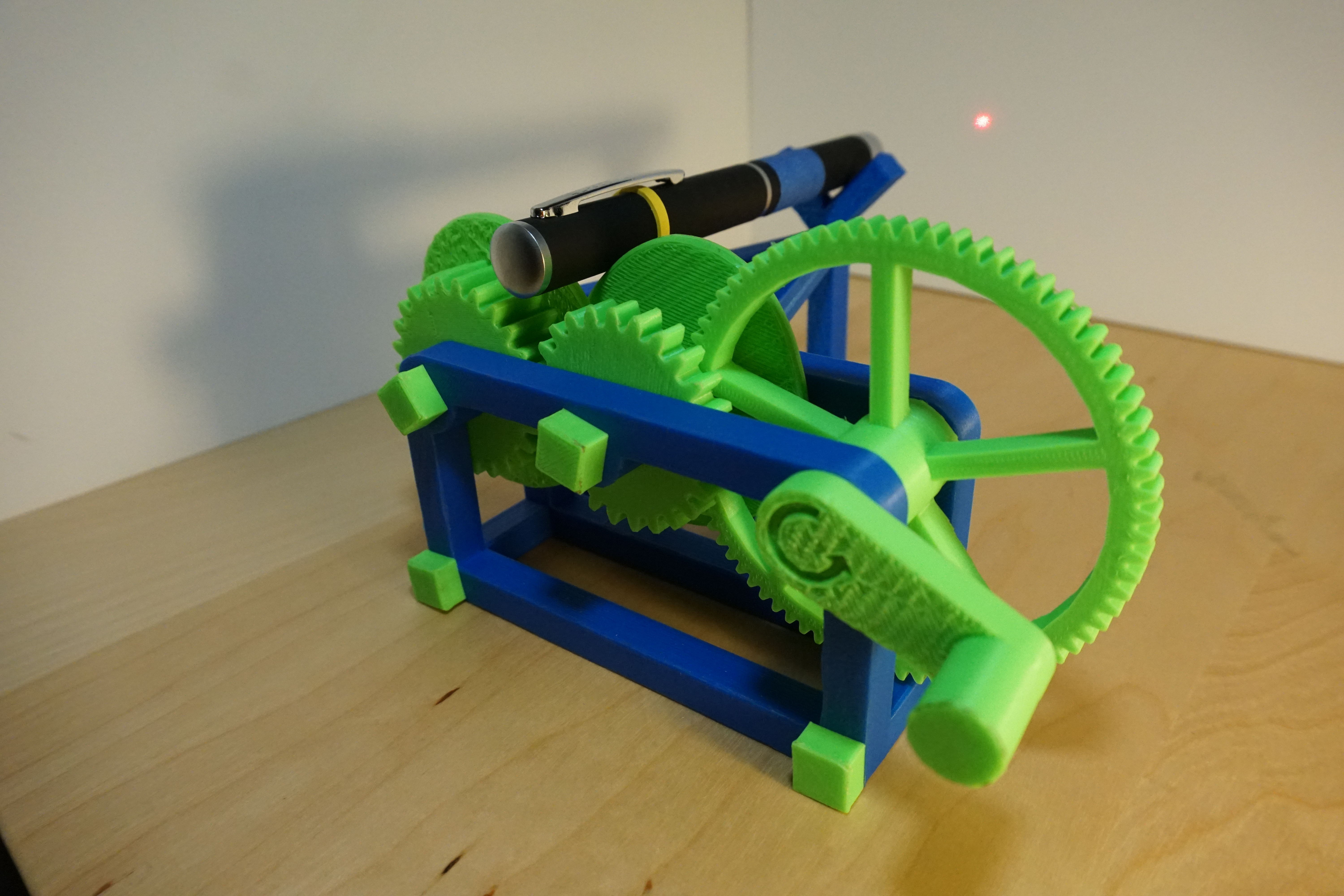
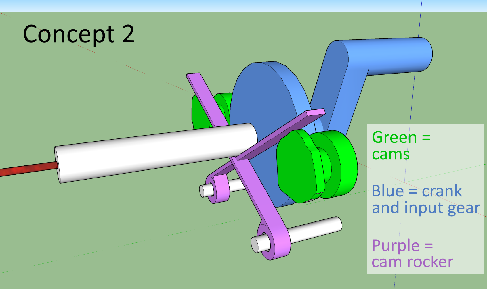
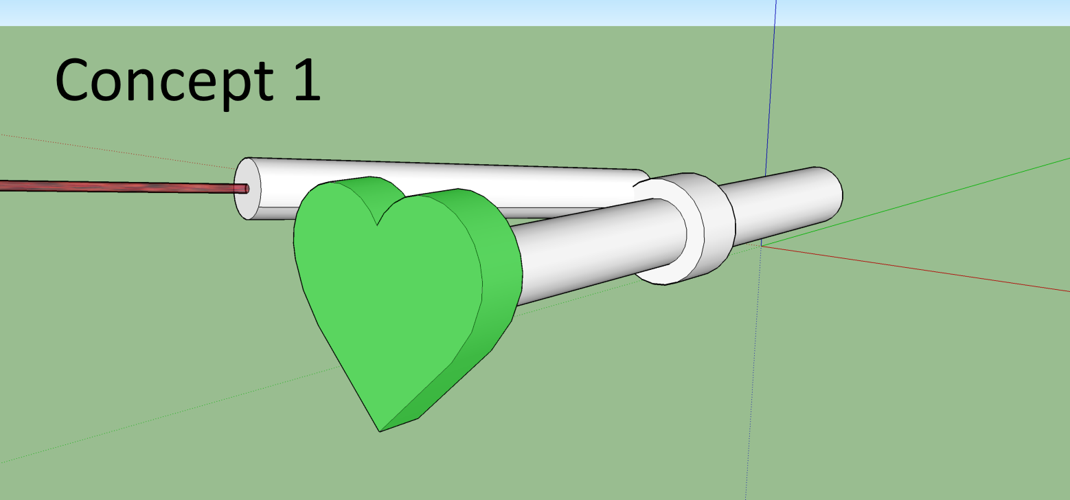
When you turn the input crank, the cams turn at a 5:1 ratio. Every time the cams rotate, the laser traces the path once. Using 2 cams allows the laser to move with 2 degrees of freedom. Basically one actuates in the X axis and one in the Y axis.
Cam profile design
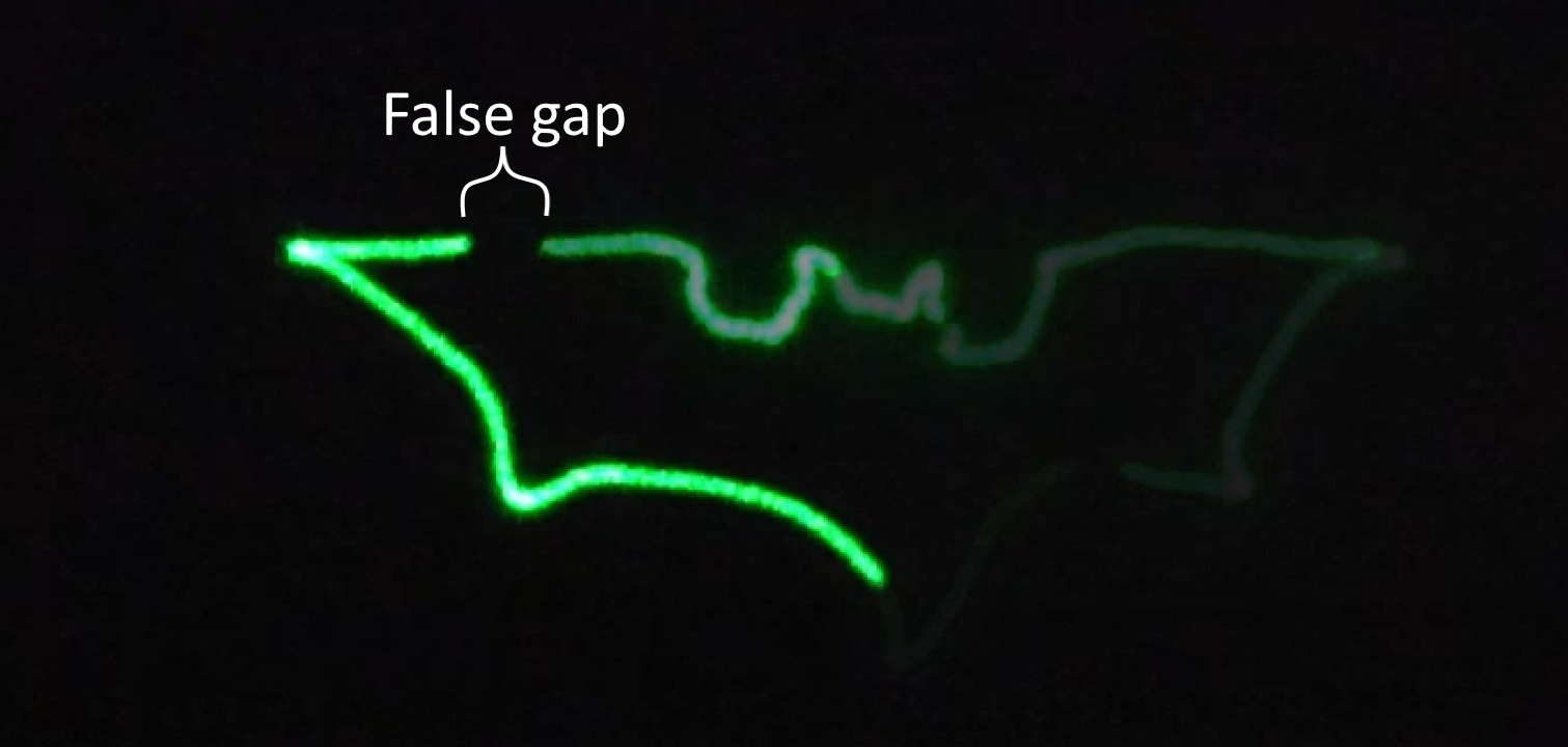
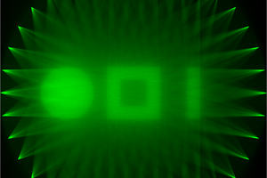
The most complicated part of the project was designing the cam profiles. To do that, I wrote a simple Go program. It takes the target path as input and outputs the 2 cam profiles. The target path is a series of points that the laser will travel to sequentially.
Here is the code (look at ConvertCoord function)
https://github.com/EvanStanford/cams/blob/master/profiler/cams.go
For more on how the math works, watch the video above.
Optimizing Mechanical Variables:
Whenever you create a physical machine, there are many factors that can be tuned to achieve the goals. Specifically, tuning all of these variables would result in a more precise output pattern and less required input power
- crank gear ratio
- too high (> 5:1)- human has too small of a mechanical advantage
- too low (< 5:1)- laser moves too slow
- rubber band force
- too much- difficult to turn, too much friction
- too little- "valve float" pen jumps off cams slightly
- Coefficient of friction between laser and cam- should be minimized
- Rotational inertia of laser pen
- If I had a very heavy laser, it would take more force to move.
- In order to minimize inertia, I flipped the pen around from my original design so the lighter nose is actuated. (The butt contains the batteries and is much heavier).


 Ted Yapo
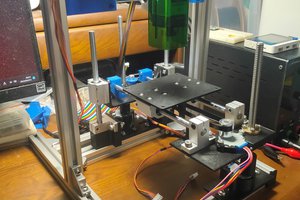
 Satoshi Tanaka
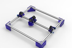
 Jason Cho
Now that is cool , well done :-)