 Bruce Land
Introduction
There are two target boards which were created by Sean Carroll:
---
The first is large and intended to be used for the lab exercise part of the course.
---
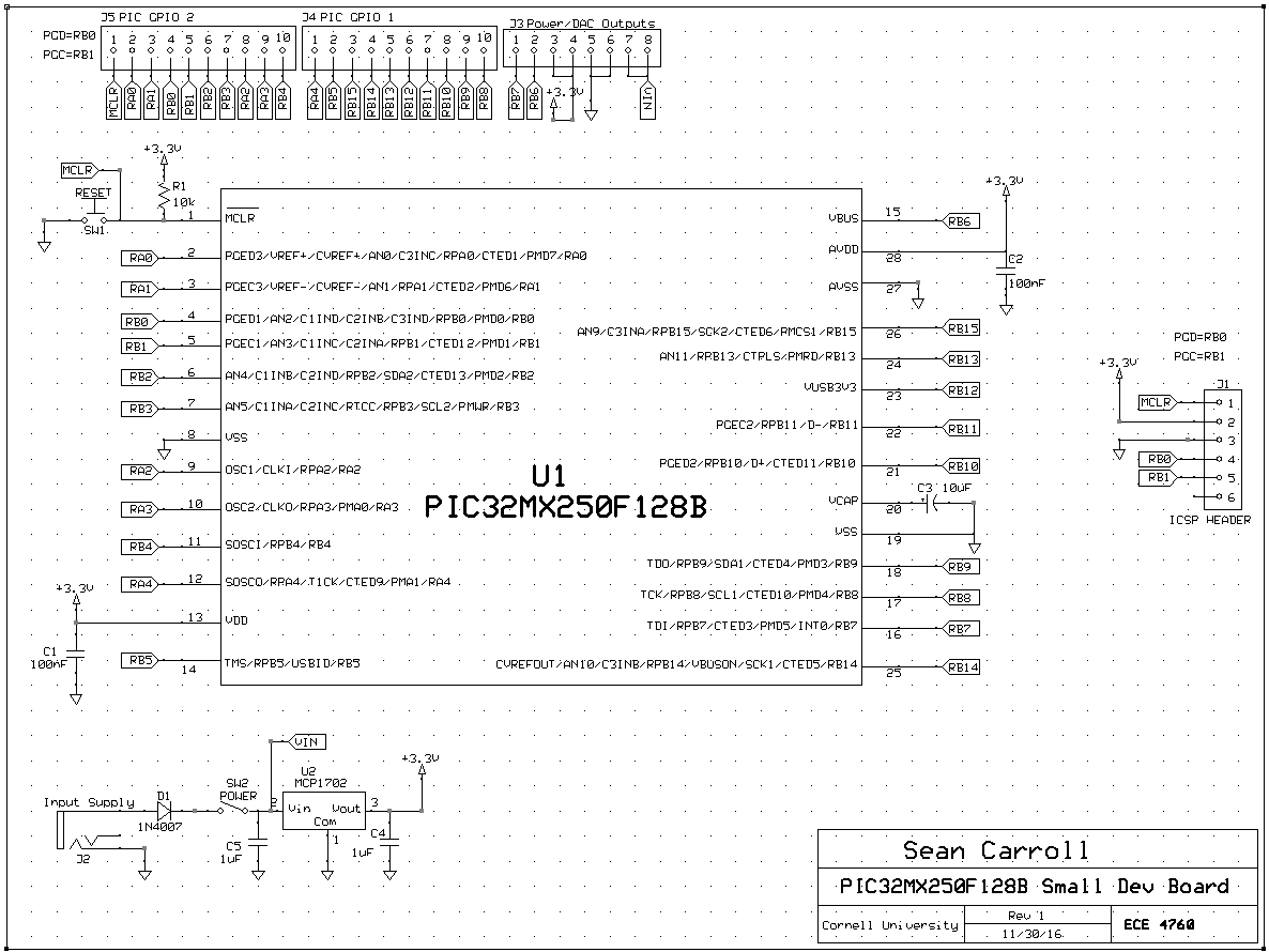
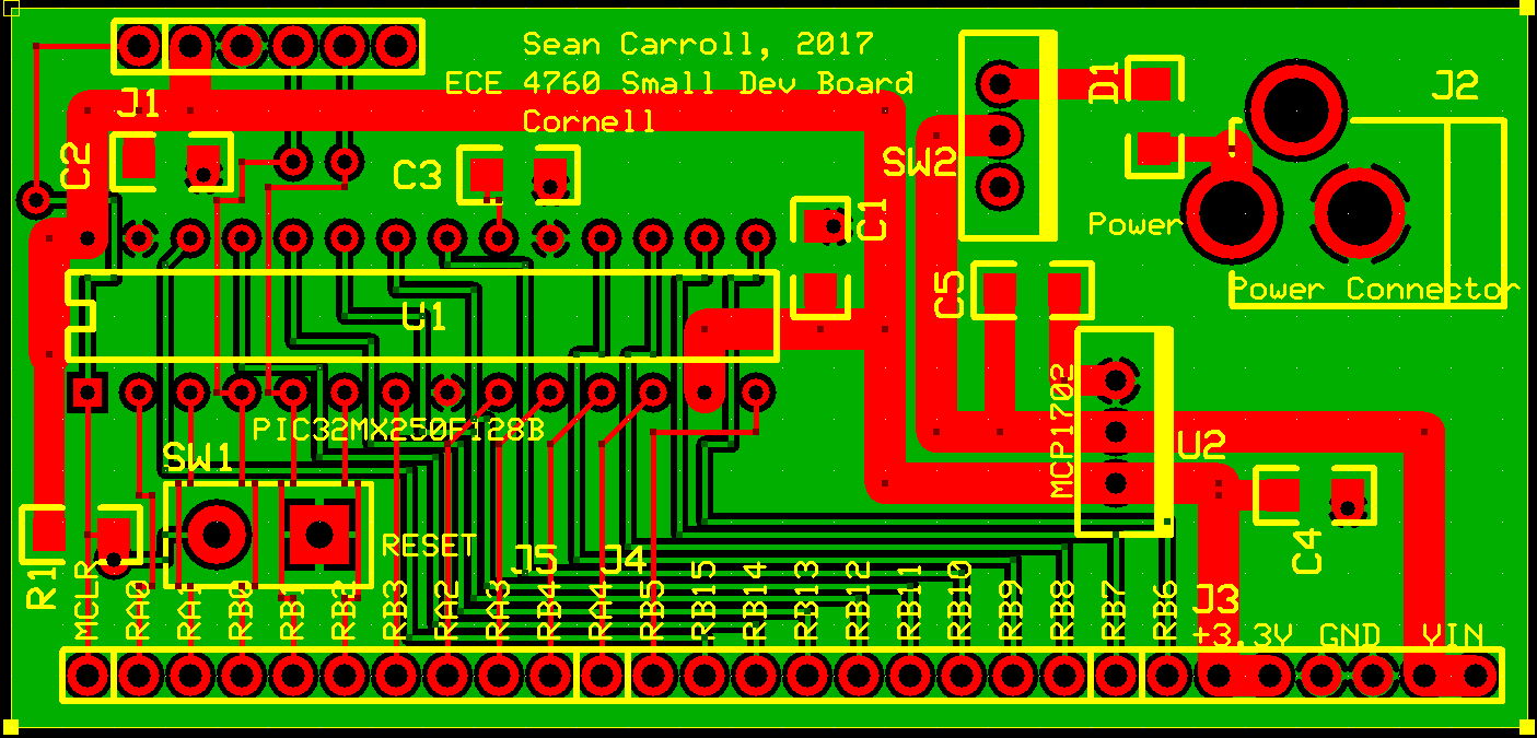
The second board is small and is intended to be a chip carrier for final projects and other space-limited uses.
Both boards are programmed using a PICkit 3 programmer/debugger, or by tapping the programming signals
from a Microstick2 (see below).
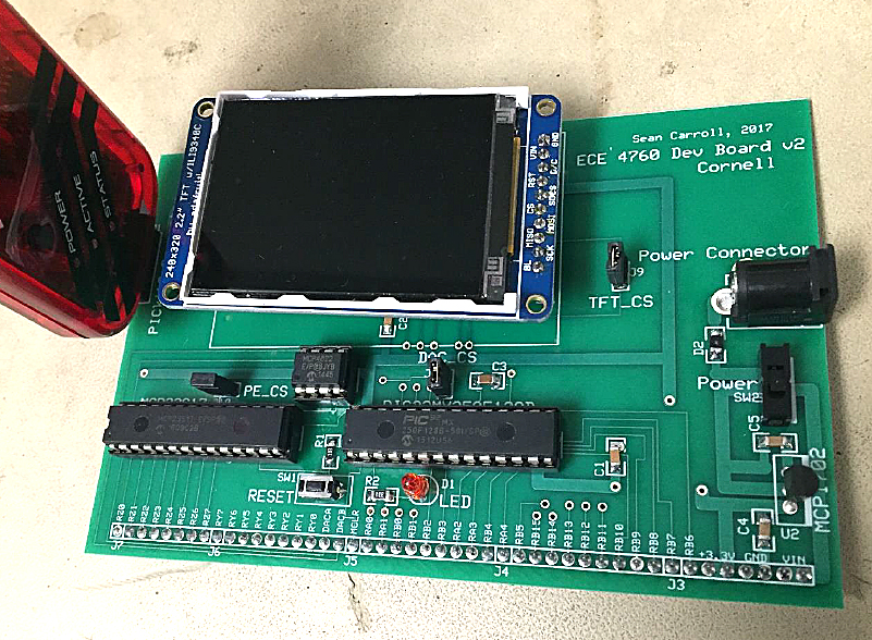
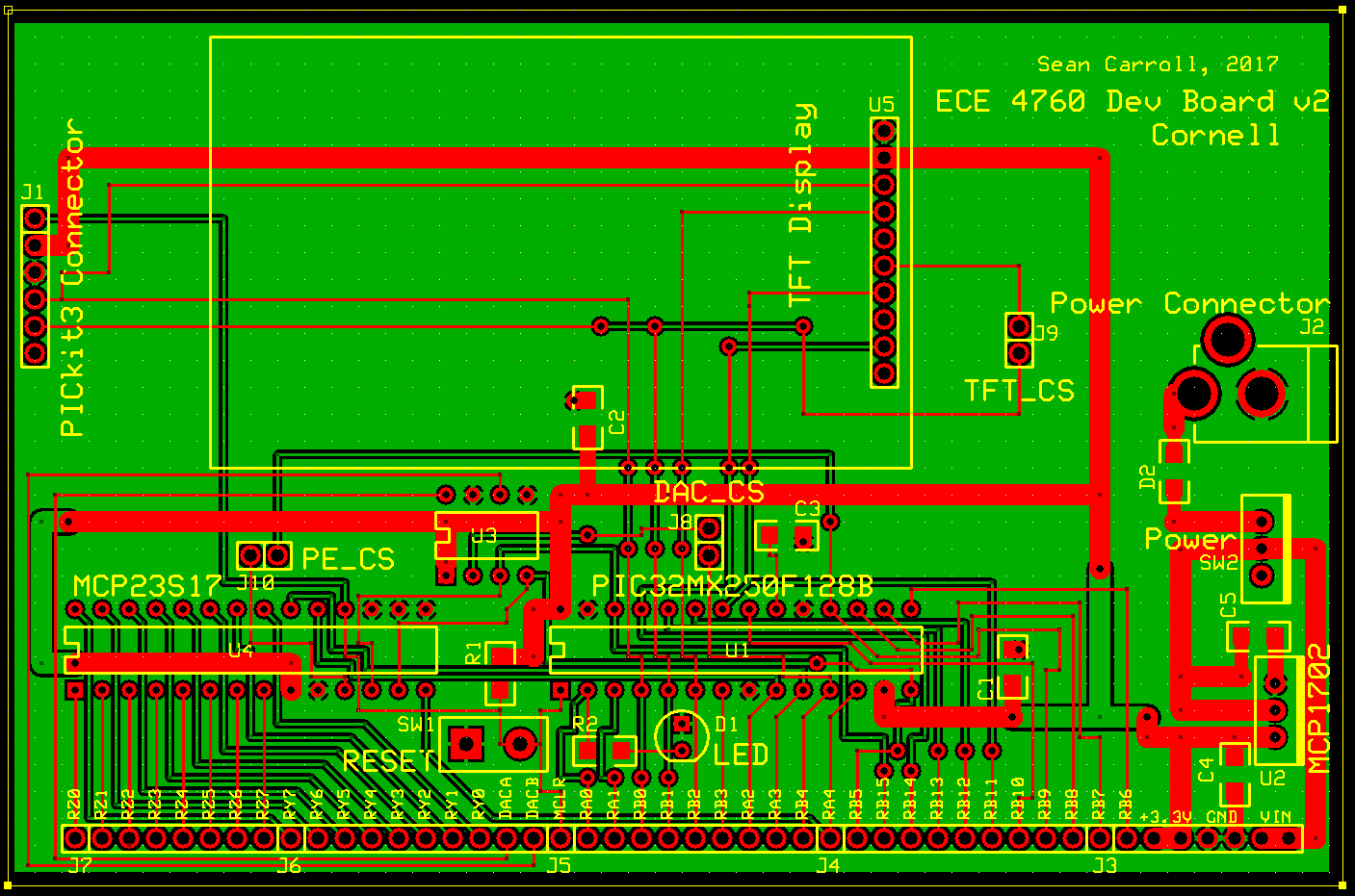
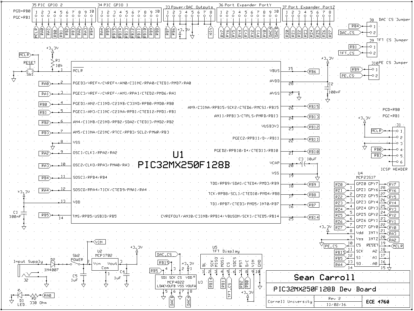
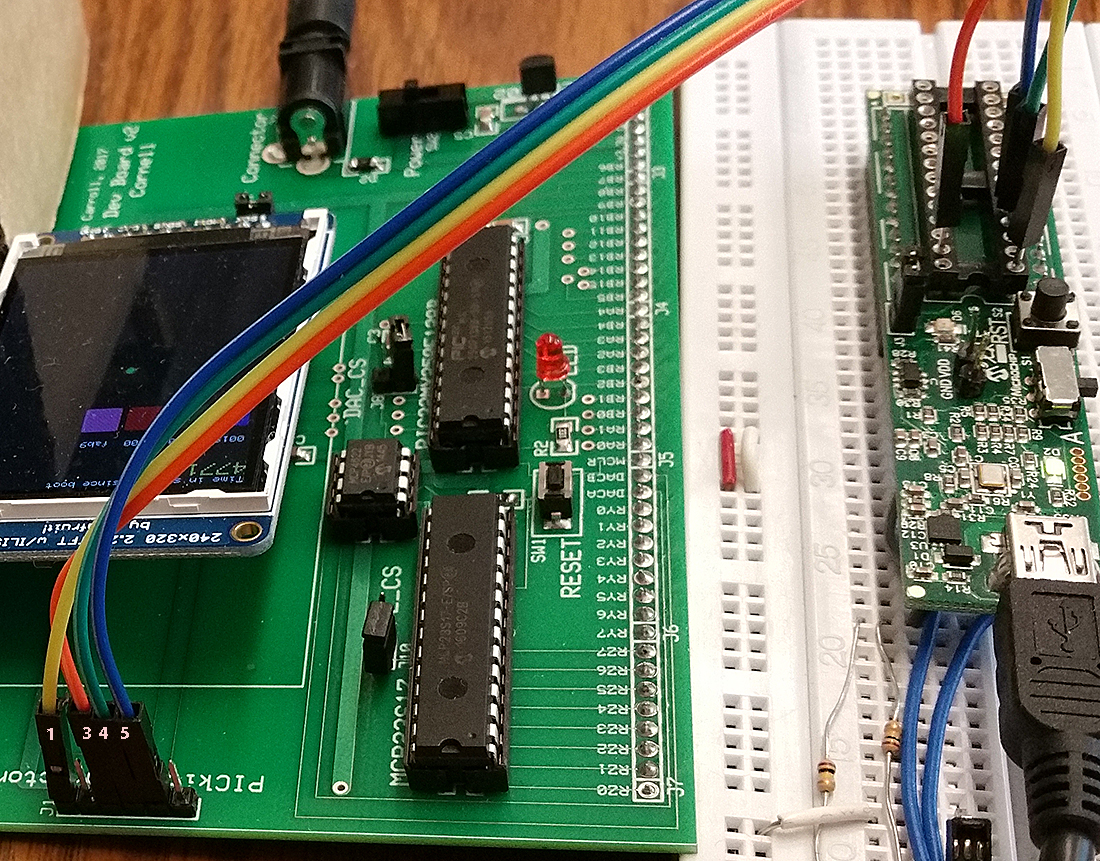
The large board
The large board features a port expander, DAC, TFT socket, programming header, and power supply.
-- Assembly instructions
-- Large board schematic and layout (ExpressPCB format)
-- Using the Port Expander and ZIP code (Sean Carroll)
-- Using the TFT LCD
-- SPI and DAC
An example uses Protothreads 1.2.1 to drive the TFT-LCD,
on-board LED and
DAC.
The example displays some graphics, blinks the LED at 0.5 Hz and
outputs a 24.4 Hz sawtooth from the DACA (DAC channel A) output pin. SPI
channel 1 runs the TFT, SPI channel 2 runs the DAC. Pin RA0 is attached
to the LED. (code, ZIP)
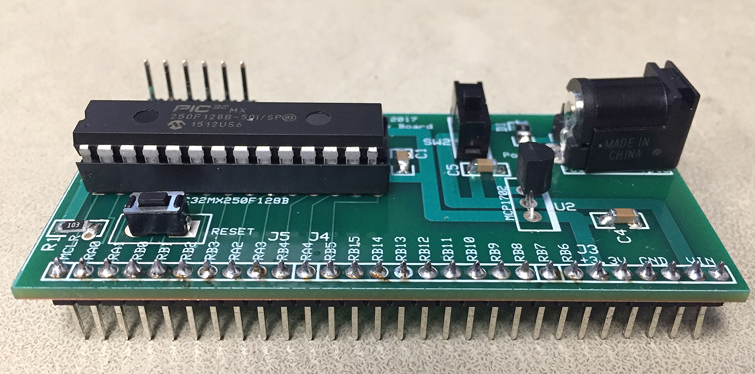
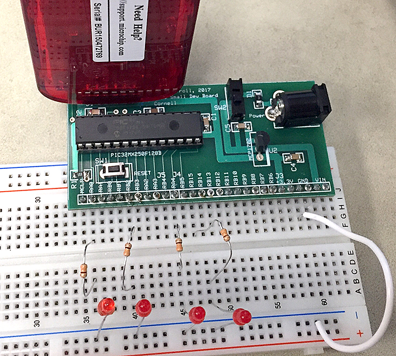
The small board
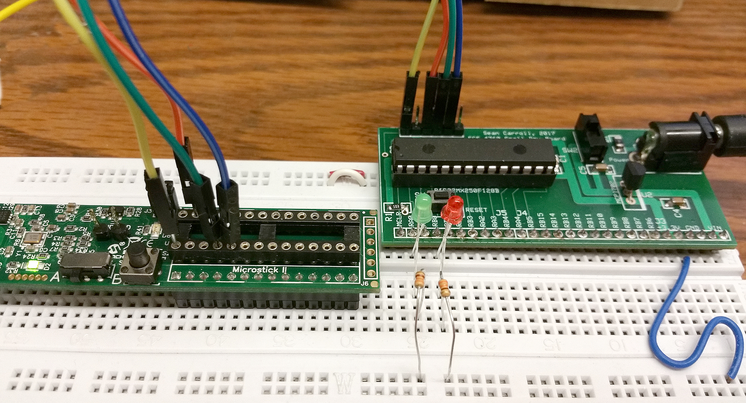
The small board is stripped down to just a MCU and power supply.
The intention is that this board can be built into projects easily.
-- Assembly instructions.
-- Small board schematic and layout (ExpressPCB format)
An example uses Protothreads 1.2.1 to drive two LEDs connected to RA0 and RB0, see picture in the
microstick2 programming section below.
(code, ZIP)
Microstick2 as a programmer
The connections to the microcontroller socket on the Microstick2 act like the standard programming signals from the PICKIT3, which was used to develop the boards you will build. On both the big and small board, J1 marks pin1 of the 6-pin ICSP header.
| Signal | PICkit3 (ICSP) connector on board |
Microstick2 DIP Pins |
|---|---|---|
| MCLR | 1 | 1 |
| ground | 3 | 27 |
| prog data (PGD) | 4 | 4 |
| prog clock (PGC) | 5 | 5 |
A wiring example is shown below. Note that pin 1, MCLR, is only available on the Microstick2 DIP socket as shown.
When you click on the small images, you will get enlargments with the pin numbers indicated.
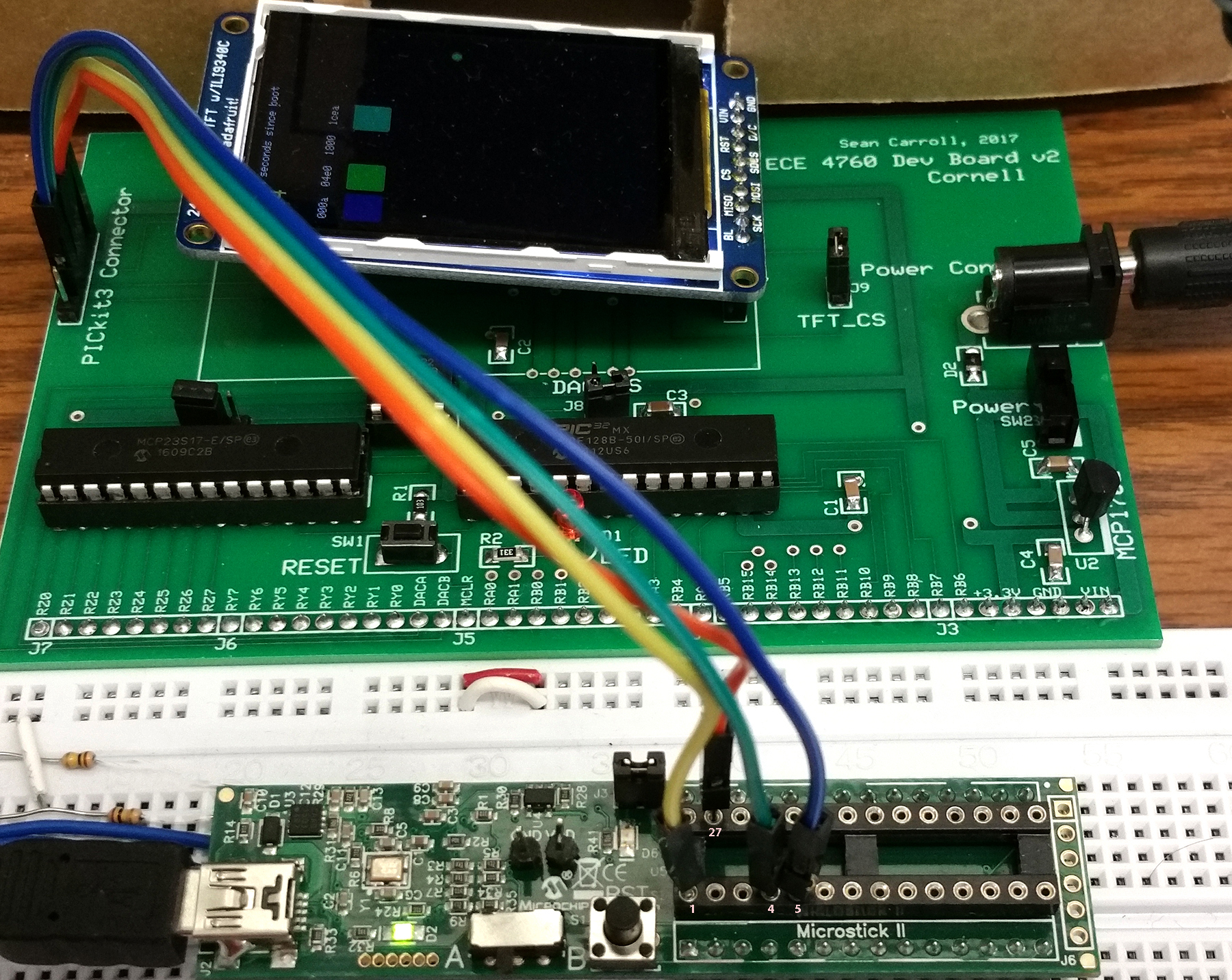
Another example with the small board.
Resources
- JTAG enable overrides pins 13, 14, and 15
- Primary oscillator enable overrides pins 9 and 10
- Secondary oscillator enalbe overrudes pins 11 and 12

 Shreyas shah
 Stephen Edwards
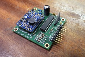
 robert
I think our education is committed to excellence. So in a couple of years, educational communities around the world were able to make a big breakthrough in helping each other. This is very inspiring. I also heard that https://www.sitejabber.com/reviews/papersowl.com has been able to help students in more than nine countries and in more than fifteen different subjects. I think this is very cool. Your board is part of it all. thank you